Table of Contents
Advertisement
Quick Links
This document is provided with the DRV10964 customer evaluation module (EVM) as a supplement to the
DRV10964 datasheet (SLDS227). It details the hardware implementation of the EVM and gives a step-by-
step introduction to the device operation.
1
...................................................................................................................
2
3
3.1
3.2
Interface Connectors (J4) for Phases of Motor
3.3
4
5
5.1
5.2
PWM Configuration With the TLC555 Timer
5.3
6
7
8
SLAU675 - February 2016
Submit Documentation Feedback
..............................................................................................
........................................................................................
..........................................................................................................
.........................................................................................................
.........................................................................................................
...............................................................................................................
..............................................................................................................
...........................................................................................................
......................................................................................................
......................................................................................................
Copyright © 2016, Texas Instruments Incorporated
DRV10964 Evaluation Module
Contents
.................................................................
....................................................................
..........................................................................
User's Guide
SLAU675 - February 2016
DRV10964 Evaluation Module
2
2
3
3
3
3
4
5
5
5
6
6
7
10
1
Advertisement
Table of Contents

Subscribe to Our Youtube Channel
Related Manuals for Texas Instruments DRV10964


Summary of Contents for Texas Instruments DRV10964
-
Page 1: Table Of Contents
SLAU675 – February 2016 DRV10964 Evaluation Module This document is provided with the DRV10964 customer evaluation module (EVM) as a supplement to the DRV10964 datasheet (SLDS227). It details the hardware implementation of the EVM and gives a step-by- step introduction to the device operation. -
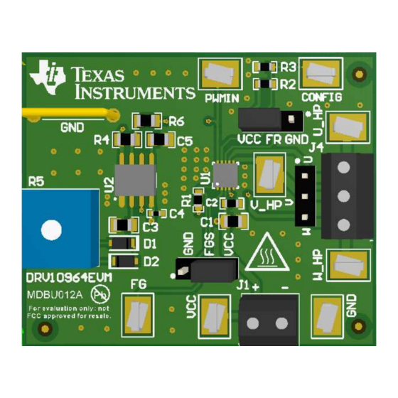
Page 2: Drv10964 Evm Kit Contents
The DRV10964 EVM is an evaluation platform for the DRV10964 three-phase brushless DC motor driver. The EVM includes a TLC555 timer configured to supply a PWM to the DRV10964 and potentiometer to adjust the speed of the motor by varying the duty cycle of the PWM. -
Page 3: Drv10964 On-Board Connections
DRV10964 On-Board Connections Power Input The DRV10964 requires an external power supply (2.1 V to 5.5 V) to operate. Connector J1 provides the required interface for the external power supply. The pin assignment of terminal P1 is as follows: Table 1. DRV10964... -
Page 4: Drv10964 Package
Table Table 4. DRV10964 Pin-Out Description FG_STATUS CONFIG The DRV10964 is packaged in a 10-pin USON package. For detailed information about the DRV10964, refer to the DRV10964 data sheet (SLDS227). DRV10964 Evaluation Module SLAU675 – February 2016 Submit Documentation Feedback... -
Page 5: User Interface
Descriptions for the jumpers are provided in the following list: • FR: Motor direction selector. Upon start-up, the DRV10964 device spins the motor in the direction indicated by the FR input pin. The direction of commutation is as described in the following table. -
Page 6: Test Points
For more information on the PWM input required by the DRV10964, refer to the datasheet (SLDS227). Test Points Test points are provided and labeled according to the inputs and outputs of the DRV10964 motor driver (see Table Table 5. -
Page 7: Tune Open To Close Loop Handoff Threshold
Tune Open to Close Loop Handoff Threshold The DRV10964 has the option of changing open to close loop handoff threshold by configuring the CONFIG pin. If there is an issue with the motor starting up, TI recommends changing the open to close loop handoff threshold. - Page 8 In such cases, it is recommended to increase the open to close loop handoff threshold. Figure 6 shows the phase current for properly tuned open to close loop handoff threshold. DRV10964 Evaluation Module SLAU675 – February 2016 Submit Documentation Feedback Copyright © 2016, Texas Instruments Incorporated...
- Page 9 Figure 4. Phase Current for High Open to Close Loop Handoff Threshold Figure 5. Phase Current for Low Open to Close Loop Handoff Threshold SLAU675 – February 2016 DRV10964 Evaluation Module Submit Documentation Feedback Copyright © 2016, Texas Instruments Incorporated...
-
Page 10: Evm Documentation
Figure 6. Phase Current for Properly Tuned Open to Close Loop Handoff Threshold EVM Documentation The EVM schematics, layout, and bill of materials (BOM) are provided in the hardware file (SLVXXX). DRV10964 Evaluation Module SLAU675 – February 2016 Submit Documentation Feedback Copyright © 2016, Texas Instruments Incorporated... - Page 11 STANDARD TERMS AND CONDITIONS FOR EVALUATION MODULES Delivery: TI delivers TI evaluation boards, kits, or modules, including any accompanying demonstration software, components, or documentation (collectively, an “EVM” or “EVMs”) to the User (“User”) in accordance with the terms and conditions set forth herein. Acceptance of the EVM is expressly subject to the following terms and conditions.
- Page 12 FCC Interference Statement for Class B EVM devices NOTE: This equipment has been tested and found to comply with the limits for a Class B digital device, pursuant to part 15 of the FCC Rules. These limits are designed to provide reasonable protection against harmful interference in a residential installation.
- Page 13 【無線電波を送信する製品の開発キットをお使いになる際の注意事項】 開発キットの中には技術基準適合証明を受けて いないものがあります。 技術適合証明を受けていないもののご使用に際しては、電波法遵守のため、以下のいずれかの 措置を取っていただく必要がありますのでご注意ください。 1. 電波法施行規則第6条第1項第1号に基づく平成18年3月28日総務省告示第173号で定められた電波暗室等の試験設備でご使用 いただく。 2. 実験局の免許を取得後ご使用いただく。 3. 技術基準適合証明を取得後ご使用いただく。 なお、本製品は、上記の「ご使用にあたっての注意」を譲渡先、移転先に通知しない限り、譲渡、移転できないものとします。 上記を遵守頂けない場合は、電波法の罰則が適用される可能性があることをご留意ください。 日本テキサス・イ ンスツルメンツ株式会社 東京都新宿区西新宿6丁目24番1号 西新宿三井ビル 3.3.3 Notice for EVMs for Power Line Communication: Please see http://www.tij.co.jp/lsds/ti_ja/general/eStore/notice_02.page 電力線搬送波通信についての開発キットをお使いになる際の注意事項については、次のところをご覧くださ い。http://www.tij.co.jp/lsds/ti_ja/general/eStore/notice_02.page SPACER EVM Use Restrictions and Warnings: 4.1 EVMS ARE NOT FOR USE IN FUNCTIONAL SAFETY AND/OR SAFETY CRITICAL EVALUATIONS, INCLUDING BUT NOT LIMITED TO EVALUATIONS OF LIFE SUPPORT APPLICATIONS.
- Page 14 Notwithstanding the foregoing, any judgment may be enforced in any United States or foreign court, and TI may seek injunctive relief in any United States or foreign court. Mailing Address: Texas Instruments, Post Office Box 655303, Dallas, Texas 75265 Copyright © 2015, Texas Instruments Incorporated...
- Page 15 IMPORTANT NOTICE Texas Instruments Incorporated and its subsidiaries (TI) reserve the right to make corrections, enhancements, improvements and other changes to its semiconductor products and services per JESD46, latest issue, and to discontinue any product or service per JESD48, latest issue.
Need help?
Do you have a question about the DRV10964 and is the answer not in the manual?
Questions and answers