Table of Contents
Advertisement
Quick Links
Advertisement
Table of Contents

Related Manuals for LawnMaster BV1210


Summary of Contents for LawnMaster BV1210
- Page 1 Operator's Manual 2-SPEED 12 AMP ELECTRIC BLOWER/VACUUM BV1210 Save this manual for future reference Read all safety rules and instructions carefully before operating this tool. Distributed By: Suzhou Cleva Electric Appliance Co., Ltd. NO.8 Ting Rong Street 215122 Suzhou - China...
-
Page 2: Table Of Contents
TABLE OF CONTENTS Section Page TABLE OF CONTENTS SPECIFICATIONS IMPORTANT SAFETY INSTRUCTIONS SYMBOLS 9-10 KNOW YOUR BLOWER 11-12 ASSEMBLY 13-15 OPERATION 16-18 MAINTENANCE TROUBLESHOOTING ® LAWNMASTER WARRANTY EXPLODED VIEW PARTS LIST NOTES... -
Page 3: Specifications
SPECIFICATIONS 2-SPEED 12 AMP ELECTRIC BLOWER/VACUUM BV1210 Voltage 120 V ~ 60 Hz Current 12 A Volume Low = 310 CFM / High = 380 CFM Air Speed Low = 180 MPH / High = 240 MPH Mulch Ratio 16:1 Unit Weight 11.8 lbs (5.35 kg) -
Page 4: Important Safety Instructions
IMPORTANT SAFETY INSTRUCTIONS IMPORTANT! READ AND UNDERSTAND ALL INSTRUCTIONS. Failure to follow all instructions listed below may result in electric shock, fire and/or serious personal injury. READ THESE INSTRUCTIONS BEFORE USING THIS BLOWER/VACUUM. WARNING TO REDUCE THE RISK OF FIRE, ELECTRIC SHOCK OR INJURY: ■... - Page 5 IMPORTANT SAFETY INSTRUCTIONS ■ Do not mis-use tool. Use the correct tool for your application. The correct tool will do the job better and safer at the rate for which it is designed. ■ Do not use on a ladder, roof top, tree, or other unstable support. Stable footing on a solid surface enables better control of the blower in unexpected situations.
- Page 6 IMPORTANT SAFETY INSTRUCTIONS ■ Never run the unit without the proper equipment attached. Always ensure the blower tubes are installed. ■ When not in use, the blower/vacuum should be stored indoors in a dry, locked up place, out of the reach of children.
- Page 7 IMPORTANT SAFETY INSTRUCTIONS ELECTRICAL CONNECTION This product has a precision-built electric motor. It should be connected to a power supply that is 120 volts, AC only (normal household current), 60 Hz. Do not operate this product on direct current (DC). A substantial voltage drop will cause a loss of power and the motor will overheat.
- Page 8 IMPORTANT SAFETY INSTRUCTIONS WARNING Check extension cords before each use. If damaged replace it immediately. Never use a product with a damaged cord since touching the damaged area could cause electrical shock resulting in serious injury. SAVE THESE INSTRUCTIONS Refer to them frequently and use them to instruct others who may use this tool. If you loan someone this tool, loan them these instructions also.
-
Page 9: Symbols
SYMBOLS Some of the following symbols may be used on this product. Please study them and learn their meaning. Proper interpretation of these symbols will allow you to operate the product better and safer. SYMBOL NAME DESIGNATION/EXPLANATION Volts Voltage Amperes Current Hertz Frequency(cycles per second) - Page 10 SYMBOLS The following signal words and meanings are intended to explain the levels of risk associated with this product. SYMBOL SIGNAL MEANING Indicates an imminently hazardous situation, which, if not DANGER avoided, will result in death or serious injury. Indicates a potentially hazardous situation, which, if not WARNING avoided, could result in death or serious injury.
-
Page 11: Know Your Blower
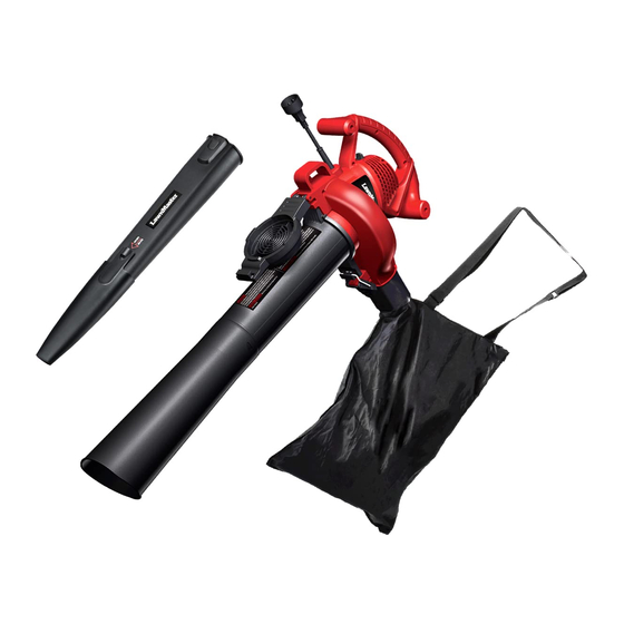
KNOW YOUR BLOWER... - Page 12 KNOW YOUR BLOWER Components 1. Main Handle 9. Blower Tube 2. ON/OFF Switch 10. Concentrator Nozzle 3. Power Cord 11. Vacuum Tubes (Upper/Lower) 4. Cord Retainer 12. Collection Bag with 5. Mulch/Vacuum Gate Connector Neck 6. Gate Latching Lock 7. Additional Grip 8.
-
Page 13: Assembly
ASSEMBLY UNPACKING This product requires assembly. ■ Carefully remove the product and any accessories from the box. Make sure that all items listed in the packing list are included. ■ Inspect the product carefully to make sure no breakage or damage occurred during shipping. ■... - Page 14 ASSEMBLY WARNING Do not connect to a power supply until assembly is complete. Failure to comply could result in accidental starting and possible serious personal injury. ASSEMBLING THE BLOWER TUBE (Fig. 1) 1. Slide blower tube forward until the tab on the blower housing clicks into the slot on the tube. 2.
- Page 15 ASSEMBLY 4. With the assembled vacuum tube properly aligned, insert into the aligned gate opening and using the latching gate lock, lock vacuum tube into place. Make certain the vacuum tube aligning tab is firmly "seated" before locking the latch (Fig. 4). Fig.
-
Page 16: Operation
OPERATION WARNING Do not allow familiarity with this type of product to make you careless. Remember that a careless fraction of a second is sufficient to inflict serious injury. WARNING Always wear eye protection with side shields marked to comply with ANSI Z87.1, along with hearing protection. - Page 17 OPERATION 4. To start the blower/vacuum, place the ON/OFF switch on I (Low Speed) or II (High Speed) position (Fig. 9). 5. To stop the blower/vacuum, place the ON/OFF switch in 0 (OFF) position (Fig. 9). I: Low Speed II: High Speed 0: OFF Fig.
- Page 18 OPERATION 6. Operate power equipment at reasonable hours only - not early in the morning or late at night when people might be disturbed. Comply with the times listed in local ordinances. 7. After using blowers or other equipment, CLEAN UP! Dispose of debris properly. 8.
-
Page 19: Maintenance
MAINTENANCE WARNING When servicing, use only identical replacement parts. Use of any other parts may create a hazard or cause product damage. WARNING Always wear eye protection with side shields marked to comply with ANSI Z87.1, along with hearing protection. Failure to do so could result in objects being thrown into your eyes, resulting in possible serious injury. -
Page 20: Troubleshooting
TROUBLESHOOTING Suspected malfunctions are often due to causes that the user can fix themselves. Therefore, check the product using this section. In most cases the problem can be solved quickly. WARNING Only perform the steps described within these instructions! All further inspection, maintenance and repair work must be performed by an authorized service center or a similarly qualified specialist if you cannot solve the problem yourself! PROBLEM POSSIBLE CAUSE... -
Page 21: Lawnmaster ® Warranty
® LAWNMASTER WARRANTY... -
Page 22: Exploded View
EXPLODED VIEW... -
Page 23: Parts List
PARTS LIST Key Number Part Number Description Quantity Power Cord Assembly Cable Clamp Assembly Micro Switch Switch Push Button Motor Housing Assembly Thermostat Button Assembly Blower Tube Assembly Concentrator Nozzle Latch Assembly Lead Wire Unit Switch Push Plate Assembly Motor Assembly Fan Blade Assembly Air Intake Cover Assembly Rear Vacuum Tube... -
Page 24: Notes
NOTES...
Need help?
Do you have a question about the BV1210 and is the answer not in the manual?
Questions and answers