Yacht Controller MAXIMO Installation Manual
Hide thumbs
Also See for MAXIMO:
- User manual (29 pages) ,
- Installer's manual (6 pages) ,
- Installer manual (8 pages)
Table of Contents
Advertisement
Quick Links
Advertisement
Table of Contents

Related Manuals for Yacht Controller MAXIMO


Summary of Contents for Yacht Controller MAXIMO
- Page 1 Receiver installation manual August 2023 Office - 4545 Ponce De Leon Boulevard - Coral Gables, FL 33146 Showroom - 1300 SE 17th Street - Fort Lauderdale, FL 33316 Phone: 305.667.5811 Fax: 305.663.5551 Toll Free: 888.898.8608 www.YachtController.com...
- Page 2 Thank you for your purchase of the Yacht Controller system. We are sure you will be well pleased with its operation and your wireless control of your yacht. If we can be of assistance to you at any time please do not hesitate to contact us via e mail.
-
Page 3: Table Of Contents
Summary SUMMARY ............................... 3 1. GENERAL FEATURES ..........................4 2. INSTALLATION AND CONNECTION ......................5 2.1. I ........................5 NSTALLATION OF THE RECEIVER 2.2. C ..........................6 ONNECTION SCHEME 2.2.1 Connection of the power supply cable ....................7 2.2.2 Connection of the engines command wires ..................8 2.2.3 Connection of the bow / stern thruster command wires (optional) ............. -
Page 4: General Features
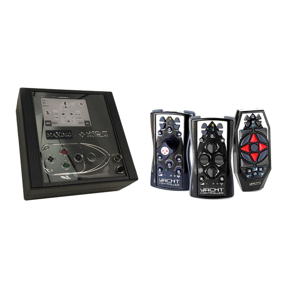
1. General features Maximo is an electronic control system capable of controlling the left and right engines, the bow and stern thrusters, anchor winches and any accessories of any boat in a simple and intuitive way. The system consists of a receiver and a transmitter for remote control. There are three transmitter models available: with keys, with levers or with Joystick. -
Page 5: Installation And Connection
2. Installation and connection 2.1. Installation of the receiver The receiver MUST be installed away from devices capable of electromagnetic interference fields for the radio signal emitted by the transmitter (for example: UHF transmitters, inverters or electric power cables, etc.). Also avoid installations where the ambient temperature can exceed 50 ° C. It is therefore forbidden to install the receiver in the engine room as this environment is subject to environmental disturbances and significant temperature changes. -
Page 6: Connection Scheme
Maximo using devices such as smartphones, tablets, PCs etc. The Wi-Fi network name (SSID) and the connection password are indicated on the receiver label and in the factory configuration attachment. 7) Check the pre-configured settings of the Maximo in the installer setup and modify them according to the connections made. ATTENTION: If the on-board control head is different from the pre-configured one in the factory settings, refer to your dealer. -
Page 7: Connection Of The Power Supply Cable
2.2.1 Connection of the power supply cable ATTENTION: Before connecting or disconnecting the central unit’s electric wires, make sure that the power supply is not present and that the helm station has been turned off. In all wiring, pay attention to the exact identification of the positive and negative cables, and to their correct connection. -
Page 8: Connection Of The Engines Command Wires
The installation of Supremo with some types of control head requires special instructions, which are provided separately. Before proceeding with the installation, check for any additional instructions. IMPORTANT: The following figure, as an example, shows how to connect analog or digital control heads. Yacht Controller interface Control Control head head... -
Page 9: Connection Of The Bow / Stern Thruster Command Wires (Optional)
2.2.3 Connection of the bow / stern thruster command wires (optional) IMPORTANT: This paragraph contains instructions for installing Supremo with On / Off thrusters. For CAN bus thrusters, see the supplied attachment. Identify the wires coming from the bow or stern thruster command joystick and connect them in parallel to the corresponding wires of the central unit. -
Page 10: Connection Of The Anchor Winch Wires (Optional)
2.2.4 Connection of the anchor winch wires (optional) Identify the wires coming from the switch of command of the anchor winch 1 or 2 and connect them in parallel to the wires of the central unit. Anchor winch 2 up Anchor winch 2 command switches Common... -
Page 11: Configuration Checking
3.1. Switch on the receiver • Activate the Maximo receiver using the on / off switch. After about 20 seconds, the receiver's beeper will begin to emit the danger intermittent signal indicating that the system is operational but has not established yet the radio connection with the transmitter. - Page 12 172.16.0.xx, in the browser it will be necessary enter 172.16.0.1). • If the operation is successful, the Maximo screen will appear on the browser page. An explanation of each of the Maximo screens is provided later in the manual.
- Page 13 From Raymarine chartplotter The Raymarine network uses the address class 10.10.0.0, the same set by default on Maximo. To connect a Raymarine chartplotter to a Maximo receiver, it is therefore necessary to follow this procedure to change the address class on Maximo.
-
Page 14: Main Screen
To connect to the Raymarine chartplotter, enter the chartplotter's Wi-Fi network selection screen. • Select MAXIMO-xxxxxxxx (where xxxxxxxx is the eight-character alphanumeric code indicated on the receiver label and on the sheet attached to the manuals) in the list of active Wi-Fi devices and click on the "Connect" button. -
Page 15: Basic Settings, The User Setup
3.4. Basic settings, the user setup User setup allows to access the system language setting screen, enter the password to access the advanced configuration setup and view the system info. Goes to the system language selection Goes to the system screen. -
Page 16: Entering The Password
3.4.2 Entering the password Allows to enter the password to access the advanced user or installer setups. If the password is correct, goes to the Numeric keyboard corresponding for entering the configuration setup, otherwise the password. message "Wrong password" will appear. -
Page 17: System Alarms
3.4.4 System alarms Shows the active or silenced alarms. It is important to check the severity of the report; if in doubt, consult your dealer. New alarms are signaled by an audible signal emitted by the receiver's beeper and by the icon on the receiver's main screen. -
Page 18: Advanced User Setup
3.5 Advanced user setup IMPORTANT: Do not change the settings of the advanced user setup if you do not have the appropriate knowledge. Allows access to the following configuration screens: Goes to the acceleration profile setting screen (optional). Goes to the bow and stern thrusters configuration Goes to the... -
Page 19: Acceleration Profile Configuration (Optional)
Available profiles. The selected profile appears highlighted in blue. 3.5.2 Acceleration profile configuration (Optional) Displays the current acceleration profile. It is possible to select a different acceleration profile or create a customized one. The acceleration percentage is intended relative to the maximum engine revolutions and is reached, depending on the profile, in the indicated time. -
Page 20: Can Thrusters Configuration
Setting custom profiles Goes to the custom To customize the acceleration acceleration profile, parameter setting select "User". screen. Acceleration values specified as a p ercentage of the maximum engine rpm and the number of seconds required to reach it. The selected field appears yellow. -
Page 21: Change Password
3.5.4 Change password Allows to change the advanced user password. Advanced user password code. Touch to go to the modify password screen. Confirm the password. An additional code entry is required. If the two codes do not match, the Numeric keyboard message - for entering the Password incorrect... -
Page 22: Wi-Fi Network Configuration
3.5.5 Wi-Fi network configuration The Maximo receiver is configured at the factory as an Access Point, i.e., as a router for Wi-Fi connection (not accessible to any other Maximo receivers located nearby). This is the standard configuration that allows connection via smartphone, tablet and PC and cannot be changed. -
Page 23: Auxiliary Wi-Fi Network Configuration (Optional)
- Insert the Dual Band Wi-Fi dongle into the USB connector of the adapter cable. - Connect the other end of the adapter cable to the second Micro USB connector (on the right) of the Maximo CPU card as shown in the figure. - Close the receiver. - Page 24 T he auxiliary Wi-Fi network Allows to set the device's network address. m ust necessarily be You can choose a dynamic address (dhcp) or, vice versa, co nfigured as "Station". This provide a static (i.e., fixed) IP address. p arameter cannot therefore be changed.
-
Page 25: Vpn (Available Only With Auxiliary Wi-Fi)
Wi-Fi Network connection (test) If the operation is successful, it displays the message "Connection established". Look in the "Info" screen the auxiliary Wi-Fi address assigned to Maximo (see the "System information" paragraph). 3.5.7 Vpn (available only with auxiliary Wi-Fi) Enable the Vpn (Virtual Private Network) channel for access to the system by the assistance service. -
Page 26: Transmitter And Receiver Software Update
3.5.8 Transmitter and receiver software update (available only with auxiliary Wi-Fi) Allows to automatically download and install the latest versions of the Maximo transmitter and receiver software. ATTENTION: Before proceeding with the update, it is necessary to connect to the Internet via your private Wi-Fi network (see the ³... - Page 27 At the end of the installation, the transmitter will restart, the receiver will turn off. FTP parameters configuration ATTENTION: To receive data, Maximo uses the FTP (File Transfer Protocol) protocol. Do not change the FTP parameters if you do not work with good reason, as unweighted changes would cause the non-reception of data.
-
Page 28: Installer Setup
3.6 Installer setup Allows access to the Maximo configuration screens. ATTENTION: Since changes in these parameters could cause system malfunctions, access to the installer setup screens is only for specialized technical personnel. Goes to the Transmitter- Receiver association screen. Goes to the receiver antenna model selection screen. -
Page 29: Antenna Configuration
3.6.2 Transmitter - Receiver association It allows to pair a single receiver with a maximum of three transmitters. Addresses of the transmitters paired with the Maximo receiver. If no transmitter has been paired with the receiver, the text - Press to associate - appears. -
Page 30: Stern And Bow Thrusters Configuration (To Be Completed)
Addresses of the transmitters turned on within the receiver's operating range. The selected address appears highlighted in blue. Cancel the transmitter - receiver pairing. 3.6.3 Stern and bow thrusters configuration (to be completed) Allows to set the operating parameters of the bow and stern CAN bow thrusters. The configurable parameters are: - The thruster model on the boat. -
Page 31: Bsa Cards
3.6.4 BSA cards Maximo automatically recognizes the presence of any BSA relay cards for commanding thrusters, bow and stern anchor winches or auxiliary devices. Bow anchor winch Keys for inverting control card. activation commands. Touch to update the screen content if the... - Page 32 WRONG CHANGES IN THE VALUES OF THE ANALOGS CAUSE SERIOUS MALFUNCTIONS. WHILE MAXIMO HAS A SECURITY FUNCTION FOR THE DEFAULT VALUES RESTORATION, IT IS ADVISABLE NOT TO PROCEED WITH THE RECALIBRATION OF THE ANALOG VALUES IF YOU DO NOT OPERATE WITH REASON.
- Page 33 Assisted trimming To carry out the assisted calibration, follow th e instructions provided by the system step by step. It is required to move the control head leves of th e right and left engines from neutral to full forward and backward and backward and forward all.
- Page 34 CAN bus control heads Select the Goes to the next control head configuration screen. model. Set in case of single engine boat. Confirm and restart the receiver. Serial control heads The system scans the receiver's 485 serial port. If an interface is detected, automatically recognizes and displays it in the box.
-
Page 35: Touch-Screen Calibration (Optional)
3.6.6 Touch-screen calibration (Optional) If the Touch Screen does not respond perfectly to finger touches, you can recalibrate it. Goes to the touch screen calibration screen. It is required to subsequently touch the crosses which will gradually be positioned at various points on the screen. -
Page 36: Paid Options
3.6.9 Virtual thrusters Maximo can simulate the presence of bow and stern thrusters using only the engines. For example, the behavior of the boat when the starboard bow thruster is active is simulated by running the starboard engine backwards and the left engine forwards. -
Page 37: Custom Rotations
3.6.10 Custom rotations Maximo allows you to set the rotation values of the boat using only the engines. For clockwise or counterclockwise rotations, for each motor, it is necessary to set the acceleration percentage, i.e. -
Page 38: The Advanced Installer Setup
3.7 The advanced installer setup Allows access to the Maximo advanced configuration screens. WARNING: Since changes to these parameters could cause system malfunctions, access to the screens of the advanced installer menu is intended only for specialized technical personnel. Go to the control heads type setting screen. Unlike the installer menu, it allows you to force the selection of a control head not installed on the boat (For more informations, see the 3.6.5... -
Page 39: Radio Test
3.7.2 Radio Test Shows a series of diagnostic information on the transmission and reception of data by the Maximo system. It also allows you to change some settings in case of noise on one of the transmission channels. -
Page 40: Adc Test
Changing the RSSI threshold Allows you to set the RSSI (Received Signal Strength Indicator) minimum power value of the received signals. All signals with power lower than the set threshold will then be rejected. 3.7.3 ADC Test Shows the internal calibration values of the DA C and ADC converters with the relative compensation values. -
Page 41: System Expansion
4. System expansion The Maximo system original configuration can be changed at any time by inserting analog or CAN bus cards. To do this, proceed as described below. Take off the power supply from the receiver and remove all the cables placed on the front of the device. -
Page 42: Troubleshooting
5. Troubleshooting This section describes some problems and malfunctions that may occur during installation, with the probable cause and - where possible - the countermeasures to be taken for their solution. Problem Possible causes Solution The receiver does not turn on. There is no voltage to the Check that the receiver is receiver. -
Page 43: Technical Specifications
6. Technical specifications Power Supply: 12 ÷ 24 VDC ± 5 % max CPU: 64-bit Quad Core 1.4 GHz Single-Board: Raspberry Pi 3 A+ Display: ´ resistive Touch Screen LCD, 800×480, HDMI. Frequencies: 433 MHz and 868 or 916 MHz Modulation: GFSK ( transmission and reception ) or OOK ( only transmission )
Need help?
Do you have a question about the MAXIMO and is the answer not in the manual?
Questions and answers