
Related Manuals for Eventide VR320


Summary of Contents for Eventide VR320
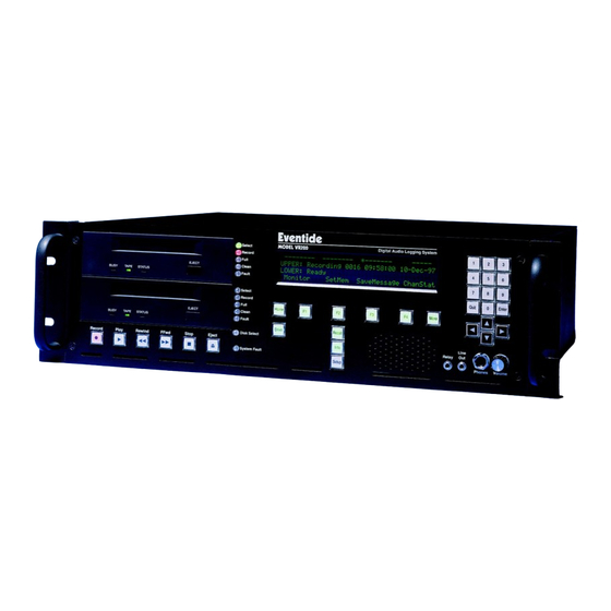
- Page 1 OPERATOR’S MANUAL MODEL VR320 AUDIO LOGGING RECORDER Eventide, Inc. One Alsan Way Little Ferry, NJ 07643 United States of America January 26, 1999 www.eventide.com...
- Page 2 This will prevent improper operation and malfunctions. • Check input power settings (paragraph 2-7). • Plan ahead for the installation of the VR320 in a convenient environment (paragraph 2-5). • Perform the following in sequence upon powerup: (1) Clear the hard drive (clear disk) (paragraph 2-3.4).
-
Page 4: Table Of Contents
Model VR320 Audio Logging Recorder TABLE OF CONTENTS Chapter Page LIST OF ILLUSTRATIONS ..................ix LIST OF TABLES....................x INTRODUCTION ....................1-1 Section I. GENERAL INFORMATION ..............1-1 INTRODUCTION ................1-1 CONFIGURATIONS ..............1-1 Section II. EQUIPMENT DESCRIPTION AND DATA........... 1-3 PURPOSE AND FEATURES............ - Page 5 Model VR320 Audio Logging Recorder Chapter Page SYSTEM CONNECTION............. 2-16 POWER CONNECTION.............. 2-16 INPUT OPTIONS ................ 2-18 2-8.1 Connecting the Telephone Channel Inputs........2-18 2-8.2 Squelch Requirements ..............2-18 2-8.3 Connecting the Audio Channel Inputs ......... 2-20 2-8.4 Audio Board Front End Options........... 2-20 2-8.5 Rear Panel Serial Port Connectors..........
-
Page 6: Chapter Page
WOW AND FLUTTER ..............4-4 CROSSTALK................. 4-4 4-10 DEGRADATION ................4-4 4-11 TAPE USAGE................4-5 Section II. THE VR320 CHANNEL HOUR CAPACITY......... 4-6 4-12 THE “CHANNEL HOUR” ............... 4-6 4-13 HARD DISK DRIVE ............... 4-8 Section III. VR320 THEORY OF OPERATION ............ 4-9 4-14 MAIN COMPONENTS .............. - Page 7 Model VR320 Audio Logging Recorder Chapter Page 4-15 GENERAL OPERATION ............... 4-9 4-16 CONCLUSION ................4-11 OPERATION ......................5-1 Section I. PREPARATION FOR OPERATION............ 5-1 GENERAL ..................5-1 MEDIA FORMATTING ..............5-1 DAT DRIVE CLEANING ..............5-3 Section II. TRANSPORT CONTROLS AND INDICATORS........5-6 TRANSPORT CONTROLS ............
- Page 8 Model VR320 Audio Logging Recorder Chapter Page 5-19 SIMULTANEOUS PLAY AND RECORD, AND RESUME .... 5-36 5-20 IMPORTANT NOTE ABOUT WRITE-PROTECTION....5-37 5-21 AUXILIARY OPERATIONS: COPY AND MAKE INDEX ..... 5-37 5-21.1 Copy.................... 5-37 5-21.2 Make Index.................. 5-40 5-22 PLAY BACK FROM THE HARD DISK......... 5-42 5-23 SEARCH FOR A PARTICULAR TIME, DATE AND CHANNEL ...
- Page 9 F-2.1 Detailed Activity Printouts.............. F-2 F-2.2 Activity Summaries................ F-2 F-2.3 Summary When Media Is Ejected ..........F-3 F-2.4 Summary on Demand ..............F-3 APPENDIX G VR320 SYSTEM TREES ............. G-1 APPENDIX H EVENTIDE DIGITAL LOGGING PRODUCTS: YEAR 2000 CONSIDERATIONS ...........H-1 INDEX ......................Index-1 WARRANTY ..................Warranty Page...
-
Page 10: List Of Illustrations
Model VR320 Audio Logging Recorder LIST OF ILLUSTRATIONS Figure No. Title Page VR320 Connections....................2-2 VR320 Front Panel ....................2-3 Removing Top Cover....................2-16 Voltage Selector Switch..................2-17 VR320 CPU: Rear Panel Serial Port Connectors..........2-21 VR320 General Block Diagram ................4-10 Jan 26/99... - Page 11 Rear Panel Audio Connector Pin-Out ..............2-19 Home Screen Description..................2-22 Drive Controls and Indicators ................2-24 Function and Soft Keys Description..............2-25 Front Panel Controls and Ports Description............2-26 Eventide VR320 Multiple Security Levels ...............3-9 Eventide Logging Recorder Channel Hours of Storage Chart.........4-7 Jan 26/99...
- Page 12 Model VR320 Audio Logging Recorder RECORD OF REVISIONS Retain this record of Revisions in the front of the manual. When you get a revision, put the revision pages in the manual. Write this date on the Record of Revisions: The date the revision was put in the manual The initial of the person who put the revision in the manual.
- Page 13 Model VR320 Audio Logging Recorder LIST OF EFFECTIVE PAGES The List of Effective Pages records not only each page of subject revision but also each previously issued page which is still correct. Pages which are no longer current do not appear on this list. If there is any question about the currency of the recipient’s copy, it is recommended that each page...
-
Page 14: Introduction
1-2. CONFIGURATIONS. Your VR320 has several features and options that are determined when the unit is ordered. It may have one or two media drives. It may have 8, 16, 24, 32, 40, or 48 audio input channels. In addition, the inputs may be configured differently depending upon your audio signal sources. - Page 15 Model VR320 Audio Logging Recorder MODEL VR320, SERIAL NUMBER _______________________ NUMBER OF DRIVES 1 (Serial number and options information appears on the rear panel data plate.) ¨ ¨ ¨ ¨ DRIVE TYPE 4MM DAT 8MM EXABYTE MAGNETO-OPTICAL DVD-RAM FIRMWARE VERSION ______________________________ (On display during turn-on, accessible from the menus.)
-
Page 16: Section Ii. Equipment Description And Data
PURPOSE AND FEATURES. 1-3.1 Purpose. The VR320 Audio Logging Recorder is a multi-channel, full-featured digital logging system. The recorder stores voice files on 4mm Digital Audio Tape (DAT) cartridge, 8mm Exabyte cassette, DVD-RAM, or magneto-optical disk and an optional hard disk (instant playback module). -
Page 17: 1-4.2 Power Requirement
Depth (main frame) 17 inches (431.8 mm) 1-4.2 Power Requirement. The VR320 is factory-configured for the line voltage of the country of installation. Fuse type is 2A, 250V, time-delay, 20 mm (Eventide P/N 316054). Same type is used for 115 Vac or 230 Vac. -
Page 18: Preparation For Use And Installation
Chapter 3 of the Operator’s Manual discusses the detailed configuration procedures for setting up your unit at your facility. It is assumed in this section that you have an audio input signal available to be connected to the VR320 Channel One input. 2-2. - Page 19 Model VR320 Audio Logging Recorder Figure 2-1. VR320 Connections Jan 26/99...
-
Page 20: Initial Turn-On
Refer to paragraph 2-7 for ensuring correct power. 2-3.1 Power. The VR320 does not have an ON/OFF switch. To apply power, first plug the power cord into the rear panel power connector. Next, plug the other end of the cord into a power outlet. - Page 21 Model VR320 Audio Logging Recorder a. Press the Home function key. This ensures that your are starting out at the “Home” screen. See the following sequence of screens. b. Press the Setup function key. UPPER: Not ready LOWER: Not ready Lock c.
-
Page 22: 2-3.5 Setting The System Clock
Press the Home function key. This ensures that you are starting out at the “Home” screen. NOTE Note that the VR320 automatically reverts to the “Home” screen after approximately one minute. This will prevent leaving the unit in an unfamiliar state for a new operator. - Page 23 Status NOTE The display will give you the time and date as stored in the VR320. This may be accurate, or completely incorrect if never set. Use the up, down and side-to-side arrow keys under the keypad to set the time and date.
- Page 24 Model VR320 Audio Logging Recorder Determine what the time and date will be in about a minute. For example, if it’s now 8:49 PM on the 2 of October, 1998, the number for 8:50 PM would be “20:50:00 02-OCT-98”. Punch in that number on the keypad and then hit the Done soft key. The display will now show the time and date as you’ve set it.
- Page 25 Model VR320 Audio Logging Recorder 2-3.6 Setting Up Input Channel 1 for Recording. a. Press the Home function key (if the system has not timed-out back to the “Home” screen). b. Press the Setup function key, then press F4 (the Board soft key).
-
Page 26: 2-3.7 Media Loading And Formatting
Make sure this is the case before continuing. On 8mm data cartridges, make sure the hole is uncovered. Insert your new tapes in the VR320 by putting them in the slots, transparent side UP, write protect latch towards you, until a gentle resistance is encountered as the tape is almost fully inserted. - Page 27 (two red holes showing) to allow the disk to be written. Make sure this is done before continuing. Insert your new magneto-optical disks in the VR320 by putting them in the slots, either side up, with the write protect latch toward you, until a gentle resistance is encountered as the disk is almost fully inserted.
- Page 28 ERASE ALL DATA ON MEDIA – ARE YOU SURE? Cancel Now that the media in the drive is formatted, notice another characteristic of the VR320. The menus are sometimes dependent upon the state of the unit. The loading of media caused new menu choices to become available.
-
Page 29: 2-3.8 Recording To The Drives
LOWER: Ready Search PrepMedia Lock Resume 2-3.8 Recording to the Drives. Once the formatted media is in one or both drives, the VR320 is ready to record. a. Press the Setup function key. b. Press F1 (the Monitor soft key). SETUP:... - Page 30 Model VR320 Audio Logging Recorder ENTER Channel # : Through Cancel d. Press F1 again (the Enable soft key). MONITORING: All Channels Disabled Enable Disable Done e. Press the number “1” on the keypad followed by the keypad Enter key.
- Page 31 If your signal source is not on, turn it on now. The top row of the display serves as a level indicator. Adjust the output level of your signal source so that the input signal to the VR320 is as high on the “meter”...
-
Page 32: Section Ii. Installation
2-5. PLANNING. Identify and allocate the inputs to be used as the signal sources for the VR320. Then determine if you have any channels remaining. If you do, bring them to a convenient patch field as you will probably find other applications for the VR320 in the future. -
Page 33: System Connection
2-6. SYSTEM CONNECTION. Figure 2-1 shows the rear panel of the VR320. There can be up to six telephone or audio input connectors, depending upon the number of optional channel boards installed. Your primary job will be to connect the input channels to your signal sources. Additional tasks include providing power, audio output, and, if desired, PC remote control, and printer interface signals and connections. - Page 34 Position top cover on the top of the VR320. Install five #6 screws. Install fifteen #4 screws. NOTE Connect signal sources and mount the VR320 prior to connecting the power source to the unit. Refer to initial turn-on (paragraph 2-3). Jan 26/99 2-17...
-
Page 35: Input Options
Model VR320 Audio Logging Recorder 2-8. INPUT OPTIONS. Up to three input boards may be installed in each VR320 mainframe (see Figure 2-2). This manual describes the three board styles available. 1) Voice-quality audio input board (8 channels). 2) FCC-registered telephone board (8 channels). - Page 36 Model VR320 Audio Logging Recorder For each of the eight channels on an input board, there are six signals available at the 50-position socket: two signals for differential audio input, one for audio output, one for squelch or record enable control, and two grounds. If there are three input boards installed, the top board contains channels 1-8, the middle board contains channels 9-16, and the bottom board contains channels 17-24.
-
Page 37: 2-8.4 Audio Board Front End Options
Model VR320 Audio Logging Recorder PAIR COLOR SIGNAL BOARD: CHANS 01-08 09-16 17-24 YEL/blu Audio in – Channel BLU/yel Audio in + YEL/org Audio out ORG/yel Ground YEL/grn Squelch GRN/yel Ground VLT/slt (not used) SLT/vlt (not used) Color Legend: WHT = white... - Page 38 Model VR320 Audio Logging Recorder Figure 2-5. VR320 CPU: Rear Panel Serial Port Connectors Jan 26/99 2-21...
-
Page 39: Section Iii. Front Panel Controls And Indicators
2-9. HOME SCREEN. This is the status or “Home” screen of the VR320. Return here at any time by pressing the “Home” soft key. You will automatically return here from all other screens after the time-out period has passed (approximately one minute for each menu level selected). Table 2-2 describes the display and controls of the “Home”... -
Page 40: Drives
Model VR320 Audio Logging Recorder Table 2-2. Home Screen Description – (Continued) ITEM CONTROL OR INDICATOR DESCRIPTION Drive Status Lines The drive status lines let you know what each drive is currently doing. In this example, the upper drive status line shows the upper drive in the record mode. - Page 41 Drives These devices may be either 4MM DAT, 8MM Exabyte cassette, rewriteable DVD-RAM, or magneto-optical disk. The VR320 logger may be equipped with a single drive or, more commonly, with dual drives. Transport Controls You may use these controls to operate both the drives and the internal hard disk.
-
Page 42: Soft Keys And Function Keys
Model VR320 Audio Logging Recorder 2-11. SOFT KEYS AND FUNCTION KEYS. Table 2-4. Function and Soft Keys Description ITEM CONTROL OR INDICATOR DESCRIPTION Soft Keys Numbered F1 through F4, these keys correspond to the commands located directly above them on the display screen. -
Page 43: Keypad, Front Panel Ports, Speaker, And Volume Control
It is often an alternative to using F4 – the Cancel or Done soft key. Enter When illuminated, this key is used to tell the VR320 to accept the number entered in by the keypad. It is often an alternative to F4 – the Done soft key. - Page 44 Model VR320 Audio Logging Recorder Table 2-5. Front Panel Controls and Ports Description – (Continued) ITEM CONTROL OR INDICATOR DESCRIPTION Arrow Keys Use the left and right arrow keys when you wish the cursor on the display to move sideways. The up and...
-
Page 45: Software Configuration
3-1. DESCRIPTION. Setup is a configuration procedure performed from the front panel of the VR320. At this point, we assume that the unit is connected to power and audio, and is powered up. If so, you will be looking at an LCD display with a legend indicating either Ready or Not Ready depending upon whether the drive is loaded. - Page 46 This may be very close to accurate, or completely incorrect if never set. The clock is powered by a lithium battery that allows it to keep time even if no power is applied to the VR320. If the battery is discharged, the date and time will be wrong.
-
Page 47: Section Ii. Global System Configuration
As discussed elsewhere in this manual, the number of samples determine the media usage. This is a linear function. Doubling the sampling rate reduces the recording time by half. The audio quality of the VR320 is dependent on the sampling rate. Jan 26/99... - Page 48 Model VR320 Audio Logging Recorder From the Home screen: a. Press Setup function key. b. Press F3 (System soft key). SETUP: Monitor Lock System Board c. Press F1 (the Sampling soft key). SYSTEM CONFIGURATION: Sampling Security MediaUsage Playback d. By pressing F3, Change cycles through the 3 available sampling rates:...
-
Page 49: Security
A technical note: Normally one would expect sampling rate to change frequency response. The VR320 has a fixed frequency response of slightly over 3 kHz. This would normally imply a sampling rate of about 8kHz and, in an 8-bit system like this one, a 64K (8 times 8) bit per second sampling rate would be required. - Page 50 Lock ChangPaswd (Change password) – When the VR320 is shipped, it is initialized with an 8- digit password “00000000” (eight zeros). This will be the password unless you change it from this menu. When you press the F1 (the ChangPaswd soft key), the unit requests the original password, which you enter using the keypad.
- Page 51 If you enter the password twice and both versions are identical, the VR320 will accept the new password and the old one will then be invalid. If you do not enter the correct “old” password or if you make any mistakes during this procedure, it will abort and leave the password unchanged.
- Page 52 Model VR320 Audio Logging Recorder Cancel – Hitting this key (F4) at any point will abort, leaving the unit in an unlocked state. g. After entering the password, the screen automatically changes to the screen below and asks that you re-enter the password. Re-enter the password using the keypad.
- Page 53 Model VR320 Audio Logging Recorder Table 3-1. Eventide VR320 Multiple Security Levels LEVEL 1 LEVEL 2 LEVEL 3 LEVEL 4 USER ID # PASSWORD USER ID # PASSWORD USER ID # PASSWORD USER ID # PASSWORD SUPERVISOR: STANDARD: PLAY ONLY:...
-
Page 54: Media Usage
Model VR320 Audio Logging Recorder 3-7. MEDIA USAGE. Media Usage gives you the opportunity to decide whether to record over or prevent recording over previously recorded media. In a two-drive unit, you can load (and format, if necessary), two media. - Page 55 Model VR320 Audio Logging Recorder d. Press F3 (the Change soft key) until the option you want to select appears. MEDIA USAGE: Record over previous media Change Done MEDIA USAGE: Record over previous media – If you have selected this option under Media Usage, when the media in the second drive is full, the recorder will switch back to recording on the first one, whether or not you have removed the previously recorded media and inserted a fresh one.
-
Page 56: Playback Adjustments
Model VR320 Audio Logging Recorder In the Do NOT mode, in order to record on a drive on which media has already been recorded, it is necessary to eject the old medium and insert another. When you insert medium, the unit does not check to make sure it is new, unrecorded or even a different medium. -
Page 57: Display Ascii Character Adjustment
Model VR320 Audio Logging Recorder c. Press F4 (the Playback soft key). SYSTEM CONFIGURATION: Sampling Security MediaUsage Playback d. Select playback adjustments. PLAYBACK CONFIGURATION: Low Pass Filter: Disabled Automatic Gain Control: Disabled Press this key to toggle between “Enabled” and “Disabled”... - Page 58 Model VR320 Audio Logging Recorder b. Press F3 (the System soft key). SETUP: Monitor Lock System Board c. Press the More function key. SYSTEM CONFIGURATION: Sampling Security MediaUsage Playback d. Press F1 (the Display soft key). SYSTEM CONFIGURATION: Display StatReport...
-
Page 59: Status Report Print Out
Change Toggle between the option of standard ASCII characters or ASCII with European characters (useful if you plan to use the VR320 in a language other than English). Done Whatever is showing on the display when you press F4 (the Done soft key) will be the current configuration. - Page 60 Model VR320 Audio Logging Recorder c. Press More function key. SYSTEM CONFIGURATION: Sampling Security MediaUsage Playback d. Press F2 (the StatReport soft key). SYSTEM CONFIGURATION: Display StatReport TimeTrack LineVol The following menus are used to configure the status printer. If you have not connected a status printer, these settings should be left at their default values (Line Length: 78;...
- Page 61 Model VR320 Audio Logging Recorder Decrease reduces the length to a minimum of 78 characters by pressing or holding the button. (The setting “wraps around” to 132 if you try to reduce the length below 78.) Increase permits a line length of up to 132 characters to be selected by pressing or holding the button.
- Page 62 Print shows you how often the summary data is printed. The possible values are the same as those for collection. Note that the VR320 will not allow you to select a print interval that is shorter than the collection interval. Each printout comprises a heading and shows the interval covered by the printout.
-
Page 63: Time Track
Time Track is a feature that can be enabled to assure that the media is “always running.” One of the main advantages to the VR320 is that no space on the media is used when there is nothing to record. In some applications, however, it is desirable to have a continuous time track to be able to prove that the media was running continuously and that no input was missed because it was temporarily stopped. - Page 64 Model VR320 Audio Logging Recorder From the Home screen: a. Press the Setup function key. b. Press F3 (the System soft key). SETUP: Monitor Lock System Board c. Press the More function key. SYSTEM CONFIGURATION: Sampling Security MediaUsage Playback d. Press F3 (the TimeTrack soft key).
-
Page 65: Line Out Volume
Model VR320 Audio Logging Recorder RECORD TIME TRACK: On Change Done Change Cycles the feature from Off to On and back. Done Exits the Time Track menu. Whatever is showing on the display when you press Done will be the current configuration. -
Page 66: Language
3-13. LANGUAGE. As of this printing, the only language available in the VR320 is English. From time to time you may want to check our web site or the local trade magazines for news of the availability of French and German languages. - Page 67 Model VR320 Audio Logging Recorder b. Press F3 (the System soft key). SETUP: Monitor Lock System Board c. Press the More function key twice. SYSTEM CONFIGURATION: Sampling Security MediaUsage Playback 2 TIMES d. Press F1 (the Language soft key). SYSTEM CONFIGURATION:...
-
Page 68: Copy Configuration
PC remote control, master clock systems, and other external control devices. The VR320 supports two types of printers, an optional label printer, and an optional status printer. The label printer automatically prints a label that identifies media when it is ejected. The status printer lists and can depict graphically, activity on the individual channels. - Page 69 Model VR320 Audio Logging Recorder c. Press the More function key twice. SYSTEM CONFIGURATION: Sampling Security MediaUsage Playback 2 TIMES d. Press F3 (the Serial I/O soft key). SYSTEM CONFIGURATION: Language CopyConfig Serial I/O Set ID # CHAN: A:19.2 BIT:28...
-
Page 70: Set Id
Because this program can run multiple units, the program must know which unit it is speaking to. Even if you are only controlling a single VR320, you must set an ID#. The ID# must be sequential beginning with 01, up to 8 units. -
Page 71: C3Ecc Error Connection
Model VR320 Audio Logging Recorder e. Select the SetID# as follows: Choose an ID# by pressing the up arrow key located under the keypad. Done The new ID# will be whatever is showing on the display when you press the Done soft key. -
Page 72: Relay
Model VR320 Audio Logging Recorder c. Press the More function key three times. SYSTEM CONFIGURATION: Sampling Security MediaUsage Playback 3 TIMES d. Press F1 (the C3ECC soft key). SYSTEM CONFIGURATION: C3ECC Relay Label DiskControl C3ECC: Enabled Change Done e. Change C3ECC error correcting as follows: Change Use F3 (the Change soft key) to toggle between “Enabled”... - Page 73 Model VR320 Audio Logging Recorder RELAY CLOSES ON: appears on the top line of the display and three soft keys appear on the bottom. From the Home screen: a. Press the Setup function key. b. Press F3 (the System soft key).
- Page 74 VR320 media is playing. Fault closes the relay only when the VR320 software detects that there is some problem with the unit, such as a defective drive. “Full media” is not considered a fault.
-
Page 75: Label Titling
Assuming you have a VR320 with two tape drives. Whenever you start recording on the Upper media drive, the VR320 creates a file on the hard disk. The file name will be something like UPRFILE. Audio from the input boards is accumulated in UPRFILE. When UPRFILE grows to a certain size, most of the data in it is transferred to the upper media drive, and the size of UPRFILE is decreased. - Page 76 Model VR320 Audio Logging Recorder ACTION VR320 RESPONSE IN VR320 RESPONSE IN REMARKS AUTOMATIC MODE SEPARATE MODE The VR320 is Audio is being recorded Audio is being recorded No difference recording with no and saved to UPRFILE on and saved to UPRFILE on...
- Page 77 Model VR320 Audio Logging Recorder c. Press the More function key three times. SYSTEM CONFIGURATION: Sampling Security MediaUsage Playback 3 TIMES d. Press F4 (the DiskContrl soft key). SYSTEM CONFIGURATION: C3ECC Relay Label DiskContrl e. Change disk control as follows:...
-
Page 78: Record Verify
Model VR320 Audio Logging Recorder After selection, press F4 (the Done soft key). 3-21. RECORD VERIFY. Record Verify prevents media from being recorded without manual confirmation by the operator. Any operation that will put the unit in Record (e.g., Resume or pressing the Record button) will not perform its intended function. -
Page 79: Automatic Formatting
Model VR320 Audio Logging Recorder d. Press F1 (the RecVerify soft key). SYSTEM CONFIGURATION: RecVerify Format ClearDisk e. Select the Record Verify option as follows: RECORD VERIFICATION: Enabled Change Done Change Pressing F3 (the Change soft key) toggles between “Enabled” and “Disabled.”... - Page 80 Model VR320 Audio Logging Recorder b. Press F3 (the System soft key). SETUP: Monitor Lock System Board c. Press the More function key four times. SYSTEM CONFIGURATION: Sampling Security MediaUsage Playback 4 TIMES d. Press F2 (the Format soft key).
-
Page 81: Automatic Recording Configuration
Model VR320 Audio Logging Recorder 3-23. AUTOMATIC RECORDING CONFIGURATION. The VR320 has the capability of starting and stopping a recording automatically. You can set the start time, stop time, and select a repeat cycle that will allow you to, for instance, record every day between the hours of 08:00 and 17:30. - Page 82 Model VR320 Audio Logging Recorder d. Select the timers and cycle parameters. AUTOMATIC RECORD CONFIGURATION Enable SetTimers SetCycle ClrTimers SetTimers Allows you to set the time and date of three operations: StartRec Sets the time that the recorder begins operation.
- Page 83 The VR320 automatically gives you a 1-minute margin on start and stop. It will start a minute before you program it to, and stop a minute after you program it to stop. If this is undesirable, take this margin into account when setting the timers.
-
Page 84: Trigger
Model VR320 Audio Logging Recorder Start Timer gives the time and date at which the next scheduled recording will start. If the Cycle is set to ONCE and recording has already begun, it will show the time at which the current recording started. - Page 85 Model VR320 Audio Logging Recorder c. Press F4 (the Trigger soft key). SETUP: Clock Descriptors AutoRec Trigger d. Use the keypad up and down cursor arrows to display the channel(s) desired to be “triggered.” “None” is an option to be selected.
-
Page 86: Section Iii. System Information
3-25. INFO FUNCTION KEY. Pressing the Info function key gives you access to a host of information about the functions and status of all aspects of the VR320. 3-26. SYSTEM INFORMATION. On closer inspection you will find that this menu is not as confusing as it first appears. The top line reveals the unit serial number, software version, and the sampling rate at which it is currently recording. -
Page 87: Media Information
Model VR320 Audio Logging Recorder SYSTEM INFO: S/N 30000095 V5.03C 32 kbp Upr: Active 8:55 Cleaned 8.55 Lwr: Active 68.53 Cleaned 68.53 Descriptors Logs Printout Reset Descriptors Pressing F1 (the Descriptors soft key) allows you to cycle through the channel numbers and view the descriptors. Use the up and down arrow keys to scroll through the channel descriptors. - Page 88 Model VR320 Audio Logging Recorder From the Home screen: a. Press the Info function key. b. Press F2 (the Media soft key). INFORMATION: System Media Disk Label The following information is described as it appears along the top line of the display. The data is shown for each drive individually under the following headings: (Position) shows the current media position.
-
Page 89: Disk Information
Model VR320 Audio Logging Recorder MEDIA INFO: RecTo ReWrites Rate UPPER: 0000 0000 120m 00:00% LOWER: Not Ready UpperDesc LowerDesc c. Use cursor keys to change channels. „ UPPER: CH01: Channel 01 3-28. DISK INFORMATION. Disk information provides information about the internal hard disk (capacity and recording status). -
Page 90: Label
Model VR320 Audio Logging Recorder HARD DISK INFORMATION Hard disk capacity: 1030M Suspend Status: Not Active 3-29. LABEL. From this menu location you have yet another opportunity to print a label if you have the optional label printer connected. Refer to Appendix F. This is quite useful for determining the start and stop time on unmarked media. -
Page 91: Section Iv. Board/Channel Configuration
“descriptor” of each channel that will be recorded on the media for identification or informational purposes. These descriptors can be displayed on the same or another VR320. Pressing the Setup function key, then F4 (the Board soft key) provides four additional menu items, RecEnable, Vox, AudioGain, and NextBoard. -
Page 92: Record Enable (Recenable)
The following instructions will step through the process of configuring the first 8 channels of your VR320. To configure higher channels, simply press F4 (the NextBoard soft key) until the channels displayed on the screen are the ones you want to configure. - Page 93 NOTE There are two different sets of RecEnable options available with the VR320. One set is used when the unit is equipped with a telephone board. A different set is used with an audio board. The differences are as follows:...
-
Page 94: Vox (Voice Activated)
VOX circuitry detects a signal and there is a sufficient voltage drop indicating an Off Hook condition. Note that you cannot change the individual channel modes while the VR320 is recording since the Setup functions are only available when the unit is in a Ready mode. AUDIO BOARD RecEnable Modes Automatic, the factory default mode, records on a given channel when an audio signal is present on that channel. - Page 95 Model VR320 Audio Logging Recorder when a radio is squelched, will benefit from shorter delays. Settings from 1 second to 255 seconds are available in 1-second increments. The factory default setting is 1 second for all channels. From the Home screen: a.
-
Page 96: 3-32.2 Setting The Vox Level
Model VR320 Audio Logging Recorder e. Select the channels and hold parameters. VOX HOLD: Channel 01 : 1 sec Channel Save Cancel Select the channel for which the hold parameter is to be adjusted by pressing F1 (the Channel soft key). Its current value is shown on the upper line of the display. - Page 97 Model VR320 Audio Logging Recorder b. Press F4 (the Board soft key). SETUP: Monitor Lock System Board c. Press F2 (the VOX soft key). CONFIGURE BOARD 1: Channel 1-8 (Telephone) RecEnable AudioGain NextBoard d. Press F2 (the Level soft key).
-
Page 98: Audio Gain
Model VR320 Audio Logging Recorder Right and left arrow keys – located under the keypad will also scroll through the installed channels and show you their current settings. Horizontal or up and down arrow keys – located under the keypad will change the VOX level settings. -
Page 99: Beep
Done – saves the setting that appears on the display and exits you from this screen. 3-34. BEEP. Beep allows you to enable or disable the sound (made by the VR320’s beep generator) that lets all parties know a conversation is being recorded. Each channel has its own control. - Page 100 Model VR320 Audio Logging Recorder b. Press F4 (the Board soft key). SETUP: Monitor Lock System Board c. Press the More function key. CONFIGURE BOARD 1: Channel 1-8 (Telephone) RecEnable AudioGain NextBoard d. Press F1 (the Beep soft key). CONFIGURE BOARD 1: Channel 1-8 (Telephone)
-
Page 101: Off Hook
Cancel – exits you from this screen without saving your changes. 3-35. OFF HOOK. OffHook sets the level that the DC voltage on the telephone line must drop below for the VR320 to begin recording. The DC voltage on a telephone line is normally 48 volts. When a telephone is lifted off hook, the DC voltage drops as a result of the load that the telephone puts on the line. - Page 102 Model VR320 Audio Logging Recorder c. Press the More function key. CONFIGURE BOARD 1: Channel 1-8 (Telephone) RecEnable AudioGain NextBoard d. Press F2 (the OffHook soft key). CONFIGURE BOARD 1: Channel 1-8 (Telephone) Beep OffHook e. Select channels and OFF Hook voltage as follows:...
-
Page 103: Automatic Gain Control (Agc)
Model VR320 Audio Logging Recorder 3-36. AUTOMATIC GAIN CONTROL (AGC). AGC (Automatic Gain Control) enables or disables AGC on each record channel. The factory default is “On.” From the Home screen: a. Press the Setup function key. b. Press F4 (the Board soft key). - Page 104 Model VR320 Audio Logging Recorder e. Select channels to be enabled or disabled as follows: AUTOMATIC GAIN CONTROL: Channel 01 : On Channel Change Done Channel selects the channel for which the AGC is to be turned On or Off and shows its current value on the upper line of the display.
-
Page 105: Section V. Descriptors
Model VR320 Audio Logging Recorder Section V. DESCRIPTORS 3-37. FUNCTIONAL DESCRIPTION. Descriptors activates the menu that enables you to create and edit the individual channel descriptors. There is an important distinction between descriptors that exist on the media and those that exist in the recorder. - Page 106 Model VR320 Audio Logging Recorder d. Press F1 (the Modify soft key). CONFIGURE DESCRIPTION Modify CopyFromMedia e. Select a channel to modify using the Up and Down arrow keys located under the keypad. Hitting these keys changes the display that shows the channel number and the descriptor currently valid for that channel.
-
Page 107: Copy Descriptors
Descriptors (on the secondary menu) is a powerful and hence potentially “dangerous” option that will copy the channel descriptors from the media in the selected drive to the memory of the VR320. The “danger” lies in the fact that it is time consuming to enter descriptors manually and, once they have been changed, the only way to get the original ones back is to re-enter them, unless, of course, you have media with the original descriptors. - Page 108 Model VR320 Audio Logging Recorder From the Home screen: a. Press the Setup function key. b. Press the More function key. SETUP: Monitor Lock System Board c. Press F2 (the Descriptors soft key). Clock Descriptors AutoRec Trigger d. Press F2 (the CopyFromMedia soft key).
- Page 109 Model VR320 Audio Logging Recorder e. Select from the options shown: UNIT DESCRIPTORS WILL BE LOST Continue Cancel The display shows a legend: UNIT DESCRIPTORS WILL BE LOST and two soft keys, CONTINUE and CANCEL. Hitting CONTINUE performs the copy operation. (If there is no media in the selected drive, hitting CONTINUE is the equivalent of hitting CANCEL.)
-
Page 110: Theory Of Operation
This section explains aspects of the VR320 that may not be obvious, but with which you should be familiar in order to make the best use of the unit’s capabilities. -
Page 111: Audio Quality Considerations And Tradeoffs
Model VR320 Audio Logging Recorder In digital recording, as used on the VR320, the audio signal is measured at regular intervals and converted to numbers. Instead of relying on the amount of magnetization on the tape to accurately represent an audio signal, digital recording relies on the magnetization to represent only two values –... -
Page 112: Sampling Rate In The Vr320
SAMPLING RATE IN THE VR320. In the VR320, the recording time of a tape depends on the “sampling rate” chosen via the front panel. We chose the term “sampling rate” because it is more obviously related to digital audio than “transcoding rate”, which is a more accurate term. -
Page 113: Wow And Flutter
(samples) will drip out of the bucket (memory) at a fairly constant rate whether there is one inch or several inches of water in the bucket. This type of operation explains why the tape in the VR320 does not move steadily. -
Page 114: Tape Usage
Therefore, if only two channels are active, an 8-channel VR320 will use tape only one fourth as rapidly as an 8-channel analog recorder. This, along with the rotating head technology, digital signal processing, and the nature of the tape itself, is what allows us to record so many hours on such a small tape. -
Page 115: Section Ii. The Vr320 Channel Hour Capacity
Section II. THE VR320 CHANNEL HOUR CAPACITY 4-12. THE “CHANNEL HOUR”. The VR320’s capacity is measured in channel-hours: the number of hours of a single channel that can be recorded on one tape (see Table 4-1). That number, for a 120 meter DDS-2 cassette, is about 520 hours, or some 21 days. - Page 116 Model VR320 Audio Logging Recorder Table 4-1. Eventide Logging Recorder Channel Hours* of Storage Chart Models VR320, VR240, VR204 VR320HF, VR240HF, VR204HF Bandwidth 3.4kHz 3.4kHz 3.4kHz 3.5kHz 7kHz 14.4kHz Sample Rate 8kHz 8kHz 8kHz 8kHz 16kHz 32kHz Compression Rate 16kbps...
-
Page 117: Hard Disk Drive
Another benefit of the hard disk drive in the VR320 is that it prolongs the life of the tape drives. Here’s why: a DDS tape drive is either “streaming” (recording data on tape at a fixed rate of about 500KB per second) or it is stopped. -
Page 118: Section Iii. Vr320 Theory Of Operation
Updates are created periodically to add new features and to support different types of SCSI removable-media drives (such as the new DVD-RAM drives). The VR320 can be controlled from the front panel or it can be operated remotely via RS-232, RS- 485, or Ethernet. - Page 119 Switcher for +5V, +12V, -12V SCSI, Ethernet, GPS Uninterruptible Switch to Battery AC Fail Detect, Battery & Charger UPPER DRIVE Tape, Optical Disk, DVD-RAM SCSI BUS LOWER DRIVER Tape, Optical Disk, DVD-RAM HARD DISK Figure 4-1. VR320 General Block Diagram 4-10 Jan 26/99...
-
Page 120: Conclusion
Model VR320 Audio Logging Recorder 4-16. CONCLUSION. This chapter has attempted to explain the philosophy behind the VR320 digital logger. We hope that by knowing how the unit works you will not be surprised when the operation is not quite the same as an analog machine, and we hope you will come to appreciate the benefits of digital logging. -
Page 121: Operation
Media Info, this information is displayed. For this reason, it is important to format media on the VR320 which will subsequently be used to record on it. If you format media on a machine with different descriptors, when you load it you will get a message Ready, descrip.dif. - Page 122 Model VR320 Audio Logging Recorder NOTE Media can be formatted on one drive while the other drive is recording. a. Insert new media in the drive slowly until you feel resistance. Gently continue pressing forward. The drive will swallow the tape or disk and try to load it. (The display will show that the drive is loading, and, shortly thereafter, indicate that the media is “unreadable.”) Use the...
-
Page 123: Dat Drive Cleaning
The media will now be formatted, a process that requires approximately 4 minutes for a tape, 30 seconds for a magneto-optical disk. If you have a stack of media to format and a dual drive VR320, you can save time by formatting on both drives at once. While one drive is formatting, use the Drive function key to select the other drive, and repeat the above steps. - Page 124 Clean the drive by inserting a DDS cleaning cartridge, such as the one supplied with the VR320. Wait for it to pop out. Then reset the clean timers. That’s it. (The drive recognizes the cleaning tape and will automatically eject it. Do NOT use an Audio grade cleaning tape, which may not be recognized by the drive.)
- Page 125 Model VR320 Audio Logging Recorder Press F4 (the Reset soft key). SYSTEM INFO: S/N 30000095 V5.03C 32 kbp Upr: Active 8:55 Cleaned 8.55 Lwr: Active 68.53 Cleaned 68.53 Descriptors Logs Printout Reset Select the drive (upper or lower) that was cleaned by pressing:...
-
Page 126: Section Ii. Transport Controls And Indicators
Refer to Chapter 2, paragraph 2-10 for illustrated descriptions. These controls are designed to be as close as possible in operation to those on a standard tape recorder. It is possible to operate the VR320 using these controls without reference to the menus at all. 5-4. - Page 127 Rewind The Rewind key is active both when the media is stopped and when the VR320 is playing. If you hit Rewind while the media is stopped, the media will be moved from its current position to its beginning. The VR320 offers three rewind speeds. To speed up the Rewind task, press the key multiple times.
- Page 128 The Fast Forward key is active both when the media is stopped and when the VR320 is playing. If you hit FFwd while the media or optical disk is stopped, it will be moved from its current position to the end.
-
Page 129: Transport Controls Reaction Time
In the VR320, equipped with media drives (4MM DAT or 8MM Exabyte), you can not see the medium, and the recorder may have a queue of tasks to perform, so it might take longer to complete. -
Page 130: Section Iii. Signal Monitoring, Level Indicator, And Channel Status
3-36.) 5-6. MONITOR. You can confirm that your signals are present at the VR320 input and are of the correct level by using the Monitor function accessible from the Home screen while in record or from the Setup menu. - Page 131 Model VR320 Audio Logging Recorder MONITORING: All channels disabled Enable Disable Done The Monitor menu shows the keys Enable, Disable, and Done. The purpose of this submenu is to allow you to select the input channels you wish to monitor. As you enable individual or groups of channels, the signals applied to their inputs will become audible (use the volume control knob on the front panel to adjust the output volume).
- Page 132 Model VR320 Audio Logging Recorder Use the keypad to enter the channel number desired. Enter channel #: Thru Cancel Press the keypad Enter soft key. Enter channel #: 6 Thru Cancel Press F4 (the Done soft key). MONITORING: 6 Enable...
- Page 133 MONITORING: All channels disabled Enable Disable Done Press F1 (the All soft key). Enter channel #: Thru Cancel Press F4 (the Done soft key). The VR320 will immediately begin playing all active channels. MONITORING: All channels enabled Enable Disable Done Jan 26/99 5-13...
- Page 134 Model VR320 Audio Logging Recorder c. Monitor multiple channels as follows: Press F1 (the Enable soft key). MONITORING: All channels disabled Enable Disable Done Use the keypad and F2 (the Thru soft key) and select the first number of the desired sequential range of channels to monitor.
- Page 135 Model VR320 Audio Logging Recorder Press F4 (the Done soft key). The VR320 will immediately begin playing the active channels selected. MONITORING: 2-4 Enable Disable Done d. Monitor multiple channels which are not sequential as follows: Press F1 (the Enable soft key).
-
Page 136: Level Indicator
Press the keypad Enter soft key. Enter channel #: 6-9 Thru Cancel Repeat steps (1) thru (5) for additional channels to be monitored. Press F4 (the Done soft key). The VR320 will immediately begin playing the active channels selected. MONITORING: 2-4, 6-9 Enable Disable Done 5-7. -
Page 137: Channel Status During Record
Model VR320 Audio Logging Recorder channels you previously selected will again be connected to the audio output. 5-8. CHANNEL STATUS DURING RECORD. The Channel Status symbols located on the top line of the display show the status (record, monitor, or level) of the individual audio channels during recording and playback. Their functions... -
Page 138: Section Iv. Record Operation
5-9. RECORD. Once placed in the record mode, the VR320 logging recorder will record until it is stopped. Data is stored on the internal hard disk for 250, 500, or more channel hours depending on the size of the hard drive. Every three channel hours the internal hard disk automatically transfers data to a ready drive. -
Page 139: 5-9.2 Begin Recording From The Drive "Select" Position
Model VR320 Audio Logging Recorder To stop recording to the Disk Select position: a. Press the Stop transport control key. DISK: Ready Playback Monitor Search SaveMsg b. The display will read ‘STOP Disk Recording? Data will be lost.’ Press F3 (the Stop soft key). - Page 140 Model VR320 Audio Logging Recorder UPPER: Ready LOWER: Ready Search PredMedia Lock Resume c. Press the Record transport control key. d. Choose F1 (the Record soft key). NOTE When you place the drive in the record mode, recording automatically begins on the hard disk.
- Page 141 If the operator hits F2 (the Stop soft key), the LCD screen displays that the selected drive is stopping. When the operator performs the Stop-Stop steps, the VR320 buffer transfers information from the hard disk to the archive drive. If the buffer is in the process of transferring, it will complete the transfer before the LCD screen displays READY.
- Page 142 Model VR320 Audio Logging Recorder c. Press F1 (the Record soft key). UPPER: Start Dual Record? Record Cancel *------- ******** ******** ******** UPPER: Recording 0003 16:38:11 14-Sep-98 LOWER: Recording 0003 16:38:11 14-Sep-98 Monitor SetMem SaveMessage ChanStat To stop recording on both drives, press the Stop transport control key.
- Page 143 Model VR320 Audio Logging Recorder UPPER: Stopping LOWER: Recording 0007 16:40:22 14-Sep-98 Monitor SetMem SaveMessage ChanStat Jan 26/99 5-23...
-
Page 144: Section V. Detailed Description Of Record Operation
8500, equal to 500 channel hours on a 120M DAT, and if you have another media in the second drive ready to record, the VR320 will switch over to the second drive at this time. Note that this switchover occurs before the media is exhausted. -
Page 145: Automatic Media Formatting
If you insert a new media, it will be unreadable by the drive, and will be formatted immediately upon loading. If you insert media that was previously formatted on the same VR320, it does not need to be formatted (unless the descriptors are changed) and will be loaded. -
Page 146: Recording Drive Selected
Instant Recall is accessed by pressing the Recall function key. Recalling during record allows the replaying of a previous passage on any selected channel while the VR320 continues to record. This is particularly useful when the recording is being monitored in real time. - Page 147 Eventide recommends that you do change the clock for daylight savings time. If you set the clock ahead in the spring, you may have trouble in the fall.
-
Page 148: 5-13.2 Operations Available During Record With The
(If the media has been recorded beyond the Almost Full point, Resume will give you a message and exit.) If you hit the Record transport key instead of resume, the VR320 will ask if you wish to resume. -
Page 149: Routine Record Operation
This completes the description of the Record mode. In normal operation, it is likely that almost none of this information will be used with any frequency. Once installed and operational, the VR320 requires essentially no attention. If your mode of operation is typical, you will simply press the... -
Page 150: Suspend Recording On A Drive
It is time to clean the drive. The VR320 logger allows you to “suspend” recording on the drive so that you may temporarily use it for other purposes. You then “resume” recording when the drive is available. -
Page 151: Resume Recording On A Drive
Model VR320 Audio Logging Recorder process. No further user intervention is required. The drive status on the display will first read “fast-forward to end”, then “Recording.” The suspend/resume function is activated in the following manner: a. Press the Drive soft key until the green LED next to the desired drive is illuminated. -
Page 152: Description Of Search And Playback Operation
Model VR320 Audio Logging Recorder UPPER: Ready (Disk recording) LOWER: Ready Search PrepMedia Lock Resume b. The logger now prepares the media for the next transfer of recorded material from the hard disk. Press F1 (the Record soft key). UPPER: Resume Recording at end of data? Record 5-17. -
Page 153: 5-17.2 Display Status Indicators While Playing From The
This gives you the ability to find a location on the media before having to play it. It is likely that you will want to start playing at a certain time/date, and the VR320 makes this easy. Regardless of whether it is activated from Ready or while the media is playing, the Search menu operates the same way. - Page 154 VR320 will stop searching. After pressing the Play transport key, the VR320 will begin playing. If you have entered a search time that is before the beginning of the stored material, the display will indicate NOT Found and drop back two levels to the main Play menu, at which time the media will be Paused.
- Page 155 NextMessage Press this key to step through messages as they occurred from the search time forward. The VR320 looks for pauses between messages and uses them as an indication of where one message ends and another begins. Scan Scan gives you the opportunity to perform a “local” fast forward and rewind, and to watch the time while doing so.
-
Page 156: Simultaneous Play And Record, And Resume
Model VR320 Audio Logging Recorder The media counter and time/date display operate erratically in Scan. This is because at any given time you can be examining data from the media (fast), or from the memory (very fast), or waiting for the media to reposition (slow). -
Page 157: Important Note About Write-Protection
Write Protection: The digital media and magneto-optical disks have a write protect mechanism that unconditionally prevents their erasure by the VR320. By setting the plastic tab on the media, or properly positioning the switch on the optical disk, you can prevent any write operation. - Page 158 The time required to Copy is largely dependent upon how nearly full the source is. The VR320 does not automatically prevent you from attempting to copy a larger medium to a shorter one. Of course, if you do this, it may not be possible to get all the data to the destination.
- Page 159 Model VR320 Audio Logging Recorder Accidentally selecting the source media as “destination” will irretrievably destroy any data on the source media. We strongly recommend that you write protect any archival media before you insert it in the VR320. If the screen does not display the copy path that you intended, cancel the menu using the F4 soft key and, from the Home screen, use the Drive select function key to select the other drive.
-
Page 160: 5-21.2 Make Index
Model VR320 Audio Logging Recorder COPY UPPER TO LOWER: Takes up to 3 hrs WholeMedia FromHere Cancel This selection, along with the direction of the copy will be displayed. At this point it is time to commit to the copy or cancel the procedure. - Page 161 Model VR320 Audio Logging Recorder To access the Make Index feature: a. Use the Drive function key to select the drive in which the Source media is loaded. b. Press F2 (the PrepMedia soft key). UPPER: Ready LOWER: Ready Search...
-
Page 162: Play Back From The Hard Disk
Model VR320 Audio Logging Recorder INDEX UPPER: Already has a valid index Complete Fast 5-22. PLAY BACK FROM THE HARD DISK. You may search and play the previous 250, 500, or more channel hours (depending on the size of your internal hard disk) without interrupting the record process. While you are playing, the Record transport key will blink. -
Page 163: Search For A Particular Time, Date And Channel
Model VR320 Audio Logging Recorder Record Buffer Select Cancel Record Buffer SELECTED Select Cancel 5-23. SEARCH FOR A PARTICULAR TIME, DATE AND CHANNEL. From the Disk Select position showing the Home screen: a. Press F3 (the Search soft key). DISK: Ready... - Page 164 Model VR320 Audio Logging Recorder b. Press F1 (the Time/Date soft key). Using the keypad, enter the search time desired. SEARCH Record buffer Time/Date Channel # c. Press F4 (the Done soft key). SEARCH TIME: 15: 27:25 05-AUG-98 Done d. Press F3 (the Start soft key).
-
Page 165: Play Back From The Dat Or Magneto Optical Disk Drive
5-24. PLAY BACK FROM THE DAT OR MAGNETO-OPTICAL DISK DRIVE. The VR320 allows you to play archive or currently loaded media without interrupting the record process. A unit equipped with dual drives typically has the benefit of an “extra” non-recording drive. - Page 166 Model VR320 Audio Logging Recorder To search for a particular time, date and channel: a. Press the Drive function key until the Select LED is illuminated next to the desired drive. b. Press F1 (the Search soft key). UPPER: Ready...
- Page 167 Model VR320 Audio Logging Recorder e. Press F3 (the Start soft key). SEARCH UPPER: 15:44:32 07-AUG-98 Start Cancel UPPER: LOWER: Ready Cancel Once the search time/date has been located, press F1 (the PlayChan (play channel)) soft key. g. Press F1 (the Enable soft key). You may now choose a single channel or multiple channels for playback.
-
Page 168: Instant Recall
Model VR320 Audio Logging Recorder h. The VR320 will now begin playing. The volume control knob is located under the keypad. - - - - - - - - * * * * * * * * * * * * * * * *... -
Page 169: Set Memory Location
Model VR320 Audio Logging Recorder c. You may now use the Pause, Rewind and FastForward soft keys or transport controls to review the selected material. RECALL: Playing CH01 01:49:05 14-AUG-98 Pause Rewind FastForward NOTE • The rewind and fast forward speeds can be increased up to three increments by pressing the soft key or transport control key. - Page 170 Model VR320 Audio Logging Recorder SET MEMORY: 0000 09:09:46 15-Sep-98 Memory1 Memory2 Memory3 Memory4 c. Press the soft key under the memory location in which you wish to store the mark. You may want to note which location you chose as you will be asked to select it when it comes time to search the drive.
- Page 171 Memory3 Memory4 Press F3 (the Start soft key). The VR320 will search for that location. Once the location is found, the screen will display the channel status along with the media location, time, and date of the memory location. Press the Play transport key to begin playing on previously selected channels.
- Page 172 Model VR320 Audio Logging Recorder h. To end your playback session, press the Stop transport control key twice. Then press F4 (the Resume soft key) to return the drive to the record mode. 5-52 Jan 26/99...
-
Page 173: Section Vi. Key Record Operation Functional Descriptions
The LCD screen displays “Resume recording at the end of data?” If the F1 (the Record soft key) is pressed, the VR320 will fast forward to the end of the media and begin recording at the point where the media stopped. -
Page 174: Appendix A Clock Accuracy, Adjustment And Time Code Input
It has a large, configurable display that shows a time display as setup by the user. The clock generates a time code for the VR320 which will keep the VR320 accurate with respect to UTC or local time indefinitely. Further information on this clock is available from Eventide. If you use this accessory clock, most of the information in Appendix A will be of little interest and can be disregarded. -
Page 175: Clock Frequency Adjustment Procedure
A-4. TIME CODE INPUT. The VR320 provides an input for a time code generator. By sending time data, the clock of the VR320 can be automatically updated and corrected so that it remains within two seconds of the generator at all times. The time code input overrides the internal clock, so that setting the clock (or clock frequency) as described in The VR320 maintenance manual is unnecessary. -
Page 176: Configuration And Data Format
Configuration of either channel B (RS232) or channel F (RS485) may be used. In order to receive time code data, the generator must create the data in the proper format, and the RS-232 parameters of the VR320 must match those of the generator, whose data is received on RS-232 channel B. -
Page 177: Vr320 Clock Example
It is normal for the VR320 internal time to differ from that of the time code generator by up to two seconds. It is also normal for the VR320 to require up to a minute before responding to time changes commanded by the generator. -
Page 178: Status Printer Indication
When the second sequence is received, the VR320 will synchronize with it. This format is generated by Eventide’s accessory clock, described at the beginning of this Appendix, and is also an available output format from the Spectracom NETCLOCK/2. Spectracom can be reached at (716) 381-4827. -
Page 179: Appendix B 4Mm Tape Issues
These cartridges are colloquially and redundantly known as DAT tapes (Digital Audio Tape tapes). It is important to understand the differences among the tapes usable in the VR320. In some applications it may not matter which brand or quality you use; in others it may be critical. -
Page 180: The Tape Counter And Tape Capacity
B-4. THE TAPE COUNTER AND TAPE CAPACITY. The VR320 recognizes and operates with 90, 120, 125 (DDS-3 equipped machines) meter DDS tapes. The tape counter is re-calibrated depending upon the length of the tape. Therefore, “tape full” will occur in the 9900-9999 range regardless of selected length. Tape changeover, in units so equipped and configured, usually occurs in the 9600-9900 range. -
Page 181: Deliberate Erasure
If you feel you must erase a tape for security reasons, you can use a standard audio DAT recorder to record over it. Alternatively, use the COPY function of a dual-drive VR320 to record non-critical data over the material to be erased. Jan 26/99... -
Page 182: Functional Description
Because the UPS is present, the VR320 can simply ignore brief power failures. It will continue operating until power comes back. -
Page 183: Ups Precautions
Model VR320 Audio Logging Recorder C-2. UPS PRECAUTIONS. It is not impossible to defeat the UPS’ utility. If your facility is subject to frequent power failures of many seconds duration, it is possible to discharge the batteries faster than they are automatically recharged. -
Page 184: Appendix D Software Update Procedure
APPENDIX D SOFTWARE UPDATE PROCEDURE The VR320 is controlled by software contained in a pair of EPROMs on the CPU board. As with all complex software-controlled devices, it is probable that updates will be issued, both to resolve defects (“bugs”) and to enhance the product. If you receive an update from Eventide, the following procedure installs it. -
Page 185: Appendix E The Optional Label Printer
Eventide. The printer and labels are available from Eventide and many computer dealers. The printer is connected to Port B on the rear of the VR320 using the Eventide cable. The labels have two sections separated by a vertical line. The left hand section should be placed on the plastic media box. -
Page 186: User-Defined Title
Model VR320 Audio Logging Recorder A label will be printed automatically when media is recorded and then ejected. If you want to print a label without recording or ejecting, the following control sequence allows you to do so: From the Home screen press the Info key then press the F4 key (the label soft key). A label will immediately be printed. - Page 187 Model VR320 Audio Logging Recorder c. Press the More function key three times. SYSTEM CONFIGURATION Sampling Security Media Usage Playback 3 TIMES d. Press F3 (the Label soft key). SYSTEM CONFIGURATION C3ECC Relay Label DiskControl LABEL TITLE: __ Done CURSOR: Moves the underline cursor forward through the 11 possible character positions of the title.
- Page 188 DECREASE/INCREASE keys to place spaces in all character positions. To allow the greatest number of characters, the title is left-justified immediately adjacent to the Eventide Logo on the label. If you use fewer than 11 characters, we recommend adding one or two leading spaces to the title for better appearance.
-
Page 189: Appendix Fthe Status Printer
APPENDIX F THE STATUS PRINTER The VR320 has a provision for creating a printed record of channel activity. In order to take advantage of this, you must provide a “line printer” and an appropriate cable. Because of the vast selection of printers on the market, Eventide does not provide either the printer or cable. -
Page 190: Configuring The Vr320 To Output Desired System Status Reports
CONFIGURING THE VR320 TO OUTPUT DESIRED SYSTEM STATUS REPORTS. F-2.1 Detailed Activity Printouts. The VR320 can report start and stop times for each message. This feature can be enabled or disabled individually for each channel. Each activity report results in one line on the printer including time, date, input channel number, start/stop status, and descriptor. -
Page 191: F-2.3 Summary When Media Is Ejected
Contest Line 2 F-2.4 Summary on Demand. A printed summary can be requested at any time while the VR320 is recording. This summary is in addition to those programmed for automatic printing. Manually requesting a summary prints out the information available at the time it is requested, i.e., all summaries accumulated since the most recent programmed printout or manual request. - Page 192 Model VR320 Audio Logging Recorder summary lines for 09:00, 09:05, and 09:10. At 10:00, the programmed summary printout will show lines for 09:15, 09:20, and every five minutes until 09:55. Any information gathered before the manual request, including activity between 09:10 and 09:12, will already have been printed and will not be shown again.
-
Page 199: Appendix Heventide Digital Logging Products: Year 2000 Considerations
Digital Instant Recall Recorder STATEMENT The change in year from 1999 to 2000 will have no affect on the performance of any of Eventide’s digital logging recorders, playback units, or digital instant recall recorders. All of these products are designed for proper calendar operation within the 100-year period of 1989 through 2088. Any 2- digit year in the range of 00-88 is assumed to refer to actual years 2000-2088. -
Page 200: Index
Clock Frequency Adjustment Procedure..................A-2 Compromises In Logging Recorders.................... 4-2 Conclusion..........................4-16 Configurations ..........................1-2 Configuring The VR320 To Output Desired System Status Reports..........F-2 Connecting The Audio Channel Inputs..................2-8.3 Connecting The Telephone Channel Inputs ................2-8.1 Copy Configuration ........................3-14 Copy Descriptors ........................ - Page 201 Model VR320 Audio Logging Recorder Crosstalk ............................. 4-7 DAT Drive Cleaning........................5-3 Data Care And Storage ....................... B-5 Degradation..........................4-10 Deliberate Erasure........................B-8 Description Of Search And Playback Operation ................ 5-17 Description ..........................3-1 Description ..........................E-1 Detailed Activity Printouts ......................F-2.1 Disk Control..........................
- Page 202 Model VR320 Audio Logging Recorder Important Note About Write-Protection ..................5-20 Info Function Key........................3-25 Initial Setup..........................2-2 Initial Turn-On..........................2-3 Input Options ..........................2-8 Instant Recall..........................5-25 Introduction..........................1-1 Introduction..........................2-4 Keypad, Front Panel Ports, Speaker, And Volume Control ............2-12 Label Titling ..........................
- Page 203 Routine Record Operation ......................5-14 RS-232 Configuration And Data Format ..................A-5 Sampling ............................. 3-5 Sampling Rate in the VR320 ....................... 4-6 Search And Play Functions ....................... 5-18 Search For A Particular Time, Date And Channel..............5-23 Security ............................3-6 Selecting Your Tape ........................
- Page 204 Model VR320 Audio Logging Recorder Suspend Recording On A Drive ....................5-15 System Connection........................2-6 System Information........................3-26 System ............................3-4 Tape Counter And Tape Capacity....................B-4 Tape Types Available ........................B-2 Tape Usage ..........................4-11 Telephone Board Connection (Phoenix Connector) ..............2-2.1 Time Code Input ..........................A-4...
-
Page 205: Warranty
Our sole liability is to repair or replace the unit as described herein. Responsibility for Shipping To obtain service under this warranty, it is the responsibility of the customer to notify Eventide of any defects, at which time Eventide will either send replacement hardware as it determines appropriate, or will request return of the unit or of the defective module for repair.
Need help?
Do you have a question about the VR320 and is the answer not in the manual?
Questions and answers