Table of Contents

Advertisement

Quick Links

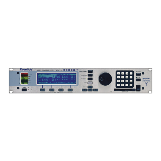
Programming Manual for
H8000, H7600, Orville and
the DSP7000 families of
®
Harmonizer
Brand Effects
Processors.
( covering H8000/H8000A/H8000FW, H7600, Orville™, DSP7000/7500™
and DSP4000B+™ )
Part No: 141035
Manual Release 1.3
19 August, 2008
©1999-2008 Eventide Inc., One Alsan Way, Little Ferry, NJ, 07643 USA
Harmonizer is a registered trademark of Eventide Inc. for its audio special effects devices incorporating pitch shift.
H8000, H8000A, H8000FW, H7600, Orville, DSP7000, DSP7500, DSP4000B+and Ultrashifter are trademarks of Eventide
Inc.

Advertisement

Table of Contents
loading
Need help?

Need help?

Do you have a question about the harmonizer H8000 and is the answer not in the manual?

Questions and answers

Summary of Contents for Eventide harmonizer H8000

  • Page 1 ©1999-2008 Eventide Inc., One Alsan Way, Little Ferry, NJ, 07643 USA Harmonizer is a registered trademark of Eventide Inc. for its audio special effects devices incorporating pitch shift. H8000, H8000A, H8000FW, H7600, Orville, DSP7000, DSP7500, DSP4000B+and Ultrashifter are trademarks of Eventide...
  • Page 2 This page intentionally left blank...
  • Page 3: Table Of Contents

    The Specifier Display Repeating Fields Editing “Special” Modules Updating the Parameters from the Harmonizer Getting Programs from the Harmonizer Creating the User Interface Viewing Menupages and Menupage Modules Interface Modules Parameter Adjusters © 1999-2008 Eventide, Inc. Page 1 of 97 Release 1.3...
  • Page 4 ODIFY Modifying a delay module Modifying Complex Modules -DSP C H8000 ......................80 NTER OMMUNICATION FOR RVILLE ..............................81 REATING THE NTERFACE Viewing Menupages and Menupage Modules Interface Modules Simple “Parameter Adjusters” © 1999-2008 Eventide, Inc. Page 2 of 97 Release 1.3...
  • Page 5 H8000, H8000A, H8000FW and in most cases, Orville as well. One of the reasons Eventide’s effects units are so versatile is that their effects programs are “modular." A single program is composed of many smaller “modules." Modules might best be thought of as good old fashioned “guitar pedals”...
  • Page 6: General Principles

    2. We must control the parameters of the modules in a program so that the desired audio effect is achieved. 3. We must make some of the parameters available in the area so that the user can PARAMETER “tweak” the program to fit a particular situation. © 1999-2008 Eventide, Inc. Page 4 of 97 Release 1.3...
  • Page 7 (If you’ve ever learned a computer language, the first thing they teach you is how to print “Hello” on the monitor!) But first we’ll take a brief detour and look at the different types of signals that interconnect modules in the Harmonizer. After that, we’ll talk about the user interface. © 1999-2008 Eventide, Inc. Page 5 of 97 Release 1.3...
  • Page 8: Different Kinds Of Signals

    Only inputs and outputs of a similar type may be interconnected (except for audio and mod inputs/outputs) given module will only have those types of inputs/outputs that are pertinent to its function. © 1999-2008 Eventide, Inc. Page 6 of 97 Release 1.3...
  • Page 9: How A Program Interfaces With The Parameter Area

    However, the user interface isn’t very “slick” and may be cumbersome to use. That’s where “custom” interface construction comes in. . . © 1999-2008 Eventide, Inc. Page 7 of 97 Release 1.3...
  • Page 10: Custom Interface

    PARAMETER Also notice that because the second knob module “took over” the filter module’s frequency control input, that parameter no longer appears on the filter module’s menu page. © 1999-2008 Eventide, Inc. Page 8 of 97 Release 1.3...
  • Page 11 PARAMETER © 1999-2008 Eventide, Inc. Page 9 of 97 Release 1.3...
  • Page 12: Modules

    (this is the program in bank 0). Normally, other, optional modules are inserted in-between the IN and OUT modules. The IN and OUT modules always remain as part of the program. © 1999-2008 Eventide, Inc. Page 10 of 97 Release 1.3...
  • Page 13: The Characteristics Of Modules

    The name may be up to 18 characters in length. To the right we see gate type module named “Ch1 Hiss Gate." © 1999-2008 Eventide, Inc. Page 11 of 97 Release 1.3...
  • Page 14 There is no input or output for specifiers; they reside “inside” a module PARAMETER (you’ll learn how to access the “inside” of a module in the Vsigfile or Patch Editor chapters). © 1999-2008 Eventide, Inc. Page 12 of 97 Release 1.3...
  • Page 15 1/4 that used for audio signals. (Of course if you go for that retro, “aliasing." dawn-of-the-samplers kind of sound, mod signals might be right up your alley!) © 1999-2008 Eventide, Inc. Page 13 of 97 Release 1.3...
  • Page 16 PARAMETER In Vsigfile, userobject inputs are always found on the left side of a module. In the Patch Editor area, userobject inputs are not explicitly shown. © 1999-2008 Eventide, Inc. Page 14 of 97 Release 1.3...
  • Page 17: Wrap Up

    If you have a computer that you can use with VSigfile, you really ought to use it (see the VSigfile Chapter for system requirements) Vsigfile is decidedly easier to use than the Patch Editor area, especially for constructing large programs. © 1999-2008 Eventide, Inc. Page 15 of 97 Release 1.3...
  • Page 18: Vsigfile

    To run Vsigfile, you will need a PC-compatible running Microsoft Windows 95, 98, XP or Vista. Macintosh users have had some success running Vsigfile under the "Virtual PC" Windows emulator, but Eventide is unable to assist in replicating this operation. To communicate with the Harmonizer you need either a Windows supported MIDI interface (typically Creative Technology’s “Soundblaster”) or an IBM PC type RS232 serial port.
  • Page 19: Establishing A Serial Connection

    Vsigfile will itself hog the comms port. To “disconnect” Vsigfile from the comms port (so that you can use another device), choose Disconnect from the Midi menu, or use AutoDisconnect which will disconnect the comms port after it has not been used for a while. © 1999-2008 Eventide, Inc. Page 17 of 97 Release 1.3...
  • Page 20: Basic Functions

    Additionally, you can change the Num field to insert more than one instance of a particular kind of module. Go ahead and insert a IIR module from the “Filter” group as shown above. © 1999-2008 Eventide, Inc. Page 18 of 97 Release 1.3...
  • Page 21: Connecting Modules

    Edit menu. NPLUGGING ONNECTIONS To unplug a connection, click on the input that terminates the connection and press the “Delete” key on the keyboard. Away it goes. . . © 1999-2008 Eventide, Inc. Page 19 of 97 Release 1.3...
  • Page 22: Display Functions

    . As a work- (see below) around, Save a program just before you use the re-Position function. If the result is worse than the original, simply reopen the saved version. © 1999-2008 Eventide, Inc. Page 20 of 97 Release 1.3...
  • Page 23: Aligning Modules

    (pink) Unconnects Shows or hides all unconnected inputs and outputs. Hiding all the unconnected inputs and outputs is useful when trying to follow the logic of a patch. © 1999-2008 Eventide, Inc. Page 21 of 97 Release 1.3...
  • Page 24: Editing

    Paste by pressing the button. Undo Selecting the Undo command under the Edit menu reverses the last change that was made to the patch. You can Undo many times in a row. © 1999-2008 Eventide, Inc. Page 22 of 97 Release 1.3...
  • Page 25 For example, the Cut command can be accomplished by holding down the “Ctrl” key and the “x” key simultaneously. Once you get proficient with Vsigfile, these shortcut keys will save you time (and you know what they say about time. . .) © 1999-2008 Eventide, Inc. Page 23 of 97 Release 1.3...
  • Page 26: Sending Programs To The Harmonizer

    Go ahead and add these modules to the program by using the Add Module command from the Edit menu. You’ll find the LFO module in the “Oscillator” group and the modfilter module in the “Filter” group. © 1999-2008 Eventide, Inc. Page 24 of 97 Release 1.3...
  • Page 27 • In our simple program these will be one in the same. We will arrange to have the parameters for both modules available in the area by connecting their userobject outputs to the PARAMETER userobject inputs of the head module. © 1999-2008 Eventide, Inc. Page 25 of 97 Release 1.3...
  • Page 28 “cornerstones,” by liberally connecting userobject outputs to the head module. Now that you’ve been introduced to the basics and have some hands-on experience, let’s move on to more advanced topics in program construction. © 1999-2008 Eventide, Inc. Page 26 of 97 Release 1.3...
  • Page 29: Advanced Features

    The name may be up to 18 characters in length, and no two modules in a given patch may share the same name. © 1999-2008 Eventide, Inc. Page 27 of 97 Release 1.3...
  • Page 30 As with all specifiers, the maximum number of taps is something you set as the program’s creator; the user will not be able to alter it. © 1999-2008 Eventide, Inc. Page 28 of 97...
  • Page 31 (‘0’ and ‘1’ in this case) If a control output is connected to this control input (as is the case shown to , its module name and output will be displayed. the right) © 1999-2008 Eventide, Inc. Page 29 of 97 Release 1.3...
  • Page 32 Display window, but they’re all variations on the theme described above. When in doubt, turn to the Modules Section for a complete description of a module’s specifiers, inputs, and outputs. © 1999-2008 Eventide, Inc. Page 30 of 97 Release 1.3...
  • Page 33: Repeating Fields

    Clicking on “adc-null” associated with in1 or “0” associated with gain1 will be sufficient. Click on either of these fields. In the upper left border of the window a button appears. © 1999-2008 Eventide, Inc. Page 31 of 97 Release 1.3...
  • Page 34 Delete Repeating Field command under the Edit menu. It’s worth noting that this is the only technique you can use to add or remove DSP inputs or outputs from your program! © 1999-2008 Eventide, Inc. Page 32 of 97 Release 1.3...
  • Page 35: Editing "Special" Modules

    Note: if you change the types, order or connections in Vsigfile after you’ve sent a program to the Harmonizer, you will not be able to Update it. You’ll get the message shown to the right. © 1999-2008 Eventide, Inc. Page 33 of 97 Release 1.3...
  • Page 36: Getting Programs From The Harmonizer

    Control, Misc, and Unconnects under the View menu and then organize the remaining modules. Then show Control and organize what appears. Finally, show Misc and organize what appears. © 1999-2008 Eventide, Inc. Page 34 of 97 Release 1.3...
  • Page 37: Creating The User Interface

    Double click on the menupage module to enter Specifier the Vsigfile Display. From here, we can see the description “delay control” and the 8 char name “DelayCtl." © 1999-2008 Eventide, Inc. Page 35 of 97 Release 1.3...
  • Page 38: Interface Modules

    “interface” module group. This group includes the common text/numerical parameter adjuster that is generated by the knob module, as well as several graphical “parameter adjusters” (hfader module, vfader module, and rfader module). © 1999-2008 Eventide, Inc. Page 36 of 97 Release 1.3...
  • Page 39: Parameter Adjusters

    The actual text used for a parameter and the way changes made to a parameter’s value in area PARAMETER translate to control output changes are set Specifier up in the Vsigfile Display. © 1999-2008 Eventide, Inc. Page 37 of 97 Release 1.3...
  • Page 40 -55.23 %5.2f ~1.23 23456.00 ~0.12 ~1.00 -55.23 %5.0f ~~~~1 23456 ~~~~0 ~~~~1 -55.23 %7.1f ~~~~1.2 23456.0 ~~~~0.1 ~~~~1.0 ~-55.23 %9.4f ~~~1.2345 23456.2345 ~~~0.1234 ~~~1.0000 ~-55.2300 1.234497 23456.001300 0.123398 1.000000 -55.234000 © 1999-2008 Eventide, Inc. Page 38 of 97 Release 1.3...
  • Page 41 Notice the difference this makes in the “step size” of the Each Delay parameter value. (You’ll have to walk yourself through this one. . .) © 1999-2008 Eventide, Inc. Page 39 of 97 Release 1.3...
  • Page 42: Simple "Parameter Adjusters

    Six characters of the 8 char name are presented on the display to the left of the graphic. The menu statement is not used. Refer to the Modules Section for complete information. © 1999-2008 Eventide, Inc. Page 40 of 97 Release 1.3...
  • Page 43 (instead of the usual resolution parameter) and a “selectable” taper waveform. The greater the taper specifier, the more non-linear the parameter response. Refer to the Modules Section for complete information. © 1999-2008 Eventide, Inc. Page 41 of 97 Release 1.3...
  • Page 44 Six characters of the 8 char name are displayed in the graphic as a title. Refer to the Modules Section for complete information. © 1999-2008 Eventide, Inc. Page 42 of 97 Release 1.3...
  • Page 45 • For meter, the name specifier is used to generate the text for the monitor. • The text fields of the monitors may include %f format numeric displays (to convey numerical as well as graphical information) © 1999-2008 Eventide, Inc. Page 43 of 97 Release 1.3...
  • Page 46 , a value of 3 text4 chooses and so on. Both the textual monitor modules create displays that are half of a screen width and one line long. © 1999-2008 Eventide, Inc. Page 44 of 97 Release 1.3...
  • Page 47: Menupages And Parameter Placement

    PARAMETER © 1999-2008 Eventide, Inc. Page 45 of 97 Release 1.3...
  • Page 48 1. main fader-obj 2. left low knob-obj 3. left high knob-obj 4. right low knob-obj 5. right high knob-obj 6. meter-obj © 1999-2008 Eventide, Inc. Page 46 of 97 Release 1.3...
  • Page 49 Therefore, a new menu page is created for the latter two knob parameters. © 1999-2008 Eventide, Inc. Page 47 of 97 Release 1.3...
  • Page 50: Tutorial 2 -Pretty In Depth

    The LFO module is found in the “Oscillator” group. Remember to add a repeating field to the mixer module by clicking on the first input and then selecting the Add Repeating Field command under the Edit menu. © 1999-2008 Eventide, Inc. Page 48 of 97...
  • Page 51 • We’ll need a “ ” parameter that selects the LFO module’s waveshape. Wave • We’ll need a “ ” parameter that controls the duty cycle of the LFO module’s waveshape. Duty © 1999-2008 Eventide, Inc. Page 49 of 97 Release 1.3...
  • Page 52 • We set the resolution to “0.1” so that a spin of the Strength results in a reasonable change in the ’s KNOB value. • We set the default value at “10” because 10 milliseconds is a pretty standard flanger strength. © 1999-2008 Eventide, Inc. Page 50 of 97 Release 1.3...
  • Page 53 • The control input on the LFO module freq accepts a value between zero and 1000. © 1999-2008 Eventide, Inc. Page 51 of 97 Release 1.3...
  • Page 54 Go ahead and add an a_to_c module from the “Bridge” group and an hmonitor module from the “Interface” group. Connect them as shown above. © 1999-2008 Eventide, Inc. Page 52 of 97 Release 1.3...
  • Page 55 1. strgth knob 1 2. feedback knob 1 3. depth knob 1 4. rate knob 1 5. wave select 1 6. duty knob 1 7. sweep mon 1 © 1999-2008 Eventide, Inc. Page 53 of 97 Release 1.3...
  • Page 56 Double click on the new menupage module and alter its specifiers as shown to the right. Follow the instructions on the next page. © 1999-2008 Eventide, Inc. Page 54 of 97 Release 1.3...
  • Page 57 LFO module as well) You’ll find that our creation of a two channel flanger could have been facilitated somewhat by using “Supermodule” functions. You’ll read about Supermodules on page 57. © 1999-2008 Eventide, Inc. Page 55 of 97 Release 1.3...
  • Page 58: Inter-Dsp Communication For H8000,Orville

    DSP B to send control signals to DSP A at the same time that DSP A is sending control signals to DSP B! This function can be used to write huge programs that span both DSPs. © 1999-2008 Eventide, Inc. Page 56 of 97 Release 1.3...
  • Page 59: Supermodules

    (by double clicking on its name directly or by entering the VSigfile Specifier Display) • Connect the ducker module’s output to its sidechain input. • Connect the ducker module’s output to DSP output 1. © 1999-2008 Eventide, Inc. Page 57 of 97 Release 1.3...
  • Page 60 . . ratiocntl cratio Ratio : %3.0f:1 gaincntl cgain Gain : %4.1f dB attackcntl cattack Attack: %6.3f Sec 0.001 0.003 decaycntl cdecay Decay: %6.3f Sec 0.001 0.4000 © 1999-2008 Eventide, Inc. Page 58 of 97 Release 1.3...
  • Page 61 Our single channel compressor is now fully functional. You can name it if you like (use the and Send “Set title,author” command under the Edit menu) it to the Harmonizer. © 1999-2008 Eventide, Inc. Page 59 of 97 Release 1.3...
  • Page 62 Library command under the SuperMod menu. Although you may edit the supermodule contents at any time (using the Edit command under the , we suggest testing and tweaking it prior to saving it to the LIBRARY. SuperMod menu) © 1999-2008 Eventide, Inc. Page 60 of 97 Release 1.3...
  • Page 63 We will now highlight each Supermodule in turn and select Rename under the SuperMod menu. In the Replacement field enter “L ” and “R ” respectively. Send the file to the Harmonizer and enjoy your dual compressor! © 1999-2008 Eventide, Inc. Page 61 of 97 Release 1.3...
  • Page 64: File Functions

    • The Save As command opens a dialog box similar to the File Open dialog box above. You can select from among the various drives and folders in your computer to save the program in the active window. You can also create or change the name of the file. © 1999-2008 Eventide, Inc. Page 62 of 97 Release 1.3...
  • Page 65: Sig" Files Versus " *.Sif" Files

    • To view files in their “Sig” format, select the as Sigfile command under the View menu. • The “Sif” file format on the other hand, does save all of the display information, but may be phased out in future versions of Vsigfile. © 1999-2008 Eventide, Inc. Page 63 of 97 Release 1.3...
  • Page 66: Patch Editor

    We want a ducker, which is in the “Dynamic” group of modules. You can either turn the until you see the little KNOB arrow pointing to ducker, or you can save a little time by © 1999-2008 Eventide, Inc. Page 64 of 97 Release 1.3...
  • Page 67 . As you move the highlighted little line between available inputs, the upper right-hand side of the display will show the currently selected input and the name of the module it resides on. © 1999-2008 Eventide, Inc. Page 65 of 97 Release 1.3...
  • Page 68 PARAMETER ducker module’s menu page. Now that you’re somewhat familiar with the mechanics of inserting and hooking modules up, let’s move on to something a little more comprehensive. © 1999-2008 Eventide, Inc. Page 66 of 97 Release 1.3...
  • Page 69: The In And Out "Modules

    (this is the program in bank 0). Normally, other, optional modules are inserted in-between the IN and OUT modules. The IN and OUT modules always remain as part of the program. © 1999-2008 Eventide, Inc. Page 67 of 97 Release 1.3...
  • Page 70: The Patch Editor Area Display

    The delay may be seen to drive five module inputs: the mixer input output input and all four of the OUT module’s inputs © 1999-2008 Eventide, Inc. Page 68 of 97 Release 1.3...
  • Page 71: Front Panel Controls

    If you hold it down, you will exit the Patch PARAMETER Editor area and return to the area. PARAMETER → To adjust the “hold time." key hold parameter on the [misc] menu page in the SETUP area. © 1999-2008 Eventide, Inc. Page 69 of 97 Release 1.3...
  • Page 72: The Patch Editor Area Soft Key Functions

    (this includes knobs, faders, etc.) are not shown in the aud only view. Note that mod signals aud only are treated like audio signals by the editor; they will show up in the view. © 1999-2008 Eventide, Inc. Page 70 of 97 Release 1.3...
  • Page 73 DSP output 1. The remaining DSP inputs and outputs are “hardwired” one to the other. Press and hold the PARAMETER key to see what this “patch” looks like. As you can see, there are two delay modules. © 1999-2008 Eventide, Inc. Page 71 of 97 Release 1.3...
  • Page 74 You'll know you have the correct output when the first delay-out upper right of the display reads . When the screen looks like the one shown to the right, press the SELECT key. © 1999-2008 Eventide, Inc. Page 72 of 97 Release 1.3...
  • Page 75 CURSOR KNOB <unplug> SOFT KEY disconnect. The will not allow a disconnect to be specified by output because outputs may be connected to more than one input. © 1999-2008 Eventide, Inc. Page 73 of 97 Release 1.3...
  • Page 76 “contains” modules instead of programs . If you don’t know how to load a program, you probably shouldn’t be reading this manual. Please read the separate User’s Manual before proceeding! © 1999-2008 Eventide, Inc. Page 74 of 97 Release 1.3...
  • Page 77 In the example to the right, the OUT module now has an unconnected input and the first module has an unconnected output <modify> Modifying a module <modify> SOFT KEY is described in the next section. © 1999-2008 Eventide, Inc. Page 75 of 97 Release 1.3...
  • Page 78: The Soft Key

    Below is a composite of the information for the first delay module in the Patch Instruct program. The above example includes several details that are familiar and a few that aren’t. The following is a breakdown of each line. © 1999-2008 Eventide, Inc. Page 76 of 97 Release 1.3...
  • Page 79 Returning to the basic Patch Editor area display ( , we can see that the by pressing the SOFT KEY) second delay module’s is indeed connected to the first delay module’s output input © 1999-2008 Eventide, Inc. Page 77 of 97 Release 1.3...
  • Page 80 “menu statement." is, in this case, the same as the module name. The text that is displayed is determined by the inherent properties of a particular module type (i.e. delay module) and may be different for other module types. © 1999-2008 Eventide, Inc. Page 78 of 97 Release 1.3...
  • Page 81: Modifying Complex Modules

    Note that since the number of control inputs in the c_switch module has changed, basic Patch Editor area display will show a different icon for the module: 1 input c_switch: 4 input c_switch: © 1999-2008 Eventide, Inc. Page 79 of 97 Release 1.3...
  • Page 82: Inter-Dsp Communication For H8000 And Orville

    DSP B. Of course, you could <insert> a c_bridge module in DSP B to send control signals to DSP A at the same time that DSP A is sending control signals to DSP B! © 1999-2008 Eventide, Inc. Page 80 of 97 Release 1.3...
  • Page 83: Creating The User Interface

    From here, we can see the “ ” and 8 char name DelayCtl “ ." Note that these equate to the title and when the menu SOFT KEY page is viewed in the area. PARAMETER © 1999-2008 Eventide, Inc. Page 81 of 97 Release 1.3...
  • Page 84 (But you may want to put the same parameter on different menu pages in the same program so that it will be accessible from more than one “place” in the program.) © 1999-2008 Eventide, Inc. Page 82 of 97 Release 1.3...
  • Page 85: Interface Modules

    . . .and it changes the value sent from the “ ’s” control output into both modules and the module (of course this screen doesn’t show the change, but the value has changed nonetheless!) . © 1999-2008 Eventide, Inc. Page 83 of 97 Release 1.3...
  • Page 86 ), and must be used as shown. If the period( ) is removed, the Harmonizer will display six digits after the decimal point. Here are example formats and results that © 1999-2008 Eventide, Inc. Page 84 of 97 Release 1.3...
  • Page 87 To the right we bump up against the new value max value And on this screen we bump up against the new max value min value You will find specifiers in most of the “interface” group modules. © 1999-2008 Eventide, Inc. Page 85 of 97 Release 1.3...
  • Page 88 Notice the difference this makes in the Each Delay “step size” of the parameter value. (You’ll have to walk yourself through this one. . .) © 1999-2008 Eventide, Inc. Page 86 of 97 Release 1.3...
  • Page 89: Simple "Parameter Adjusters

    The knob module is the most popular interface module (in factory programs). It generates a 20-character text string, menu including a very versatile numerical display from the statement . Eight of these can fit on a single menu page. © 1999-2008 Eventide, Inc. Page 87 of 97 Release 1.3...
  • Page 90 Nine characters of the menu statement are displayed above the graphic as a title. Refer to the Modules Section for complete information. © 1999-2008 Eventide, Inc. Page 88 of 97 Release 1.3...
  • Page 91 • minimum sets the lowest value that may be indicated by the monitor. • maximum sets the highest value that may be indicated by the monitor. © 1999-2008 Eventide, Inc. Page 89 of 97 Release 1.3...
  • Page 92 A control input value of 0 chooses text1 text4 , a value of 3 chooses and so on. Both the textual monitor modules create displays that are half of a screen width and one line long. © 1999-2008 Eventide, Inc. Page 90 of 97 Release 1.3...
  • Page 93 Note: If an module’s area graphic is shown more than once on a single menu page, the second instance might not be updated PARAMETER when the first instance’s value changes and vice versa. © 1999-2008 Eventide, Inc. Page 91 of 97 Release 1.3...
  • Page 94 <modify> SOFT module. This is a composite of what the can see in the head module now. This shows that the allpass-obj userobject was automatically connected to the head module. © 1999-2008 Eventide, Inc. Page 92 of 97 Release 1.3...
  • Page 95 • Go to the Patch Editor area by pressing and holding the key. PARAMETER • Select misc <aud only> display mode by pressing the key three times. • a menupage module from the interface group. <insert> © 1999-2008 Eventide, Inc. Page 93 of 97 Release 1.3...
  • Page 96 <modify> SOFT KEY on the menupage module. • Set the # entries obj2 specifier to and then set the meter-obj obj1 specifier to (same as © 1999-2008 Eventide, Inc. Page 94 of 97 Release 1.3...
  • Page 97 SOFT KEY menupage menu page is still “ ." • Press the . The second menu, whose title is “ ." SOFT KEY has only one meter module monitor on it. © 1999-2008 Eventide, Inc. Page 95 of 97 Release 1.3...
  • Page 98 The # entries is first set to the desired number (six) and then the entries are adjusted, one at a time, to connect the userobject outputs to the menupage module. © 1999-2008 Eventide, Inc. Page 96 of 97 Release 1.3...
  • Page 99 Therefore, a new menu page is created for the latter two knob parameters. © 1999-2008 Eventide, Inc. Page 97 of 97 Release 1.3...

Table of Contents