Advertisement
MV800 Modbus TCP Communication Option
1 Product information
1.1 Designation rule
1.2 Functions and specifications
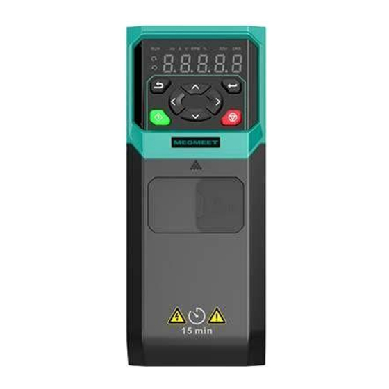
MV810-TCP01 option provides communication expansion for the MV800 drive
series. Its functions and specifications are explained below:
1.2.1 Function features
(1) Read slave parameters (0x03)
(2) Change single slave parameter (0x06)
(3) Change multiple slave parameters (0x10)
(4) Simultaneously read/write multiple slave parameters (0x17)
(5) Mutable mapping of address (use the P30 function code group for
configuration)
1.2.2 Technical specifications
Modbus TCP
connector
Communication
User Manual
Interface
Transmission mode
Transmission media
Galvanic isolation
Network standard
Transmission protocol
Transmission distance
Bus transmission speed 100 Mbps, auto-defect
Module name
Two RJ45 ports
High-speed bus
CAT5 shielded twisted pair cables
500 V DC
Modbus TCP
100 BASE-TX (IEEE 802.3)
100 m
MV810-TCP01
1
BOM Code: R33011129
Version: V00
Advertisement
Table of Contents

Subscribe to Our Youtube Channel
Related Manuals for Megmeet MV810-TCP01


Summary of Contents for Megmeet MV810-TCP01
- Page 1 Version: V00 1 Product information 1.1 Designation rule 1.2 Functions and specifications MV810-TCP01 option provides communication expansion for the MV800 drive series. Its functions and specifications are explained below: 1.2.1 Function features (1) Read slave parameters (0x03) (2) Change single slave parameter (0x06)
-
Page 2: Pin Definitions
60068-2-6) 1.3 Terminal description 1.3.1 Layout The front and back views of MV810-TCP01 are shown in Fig. 1. Fig. 1 The option has GND, two RJ45 ports and the interface connected to a drive. 1.3.2 Pin definitions Modbus TCP adopts the standard RJ45 port. MV810-TCP01 option has two RJ45... - Page 3 NOT CONNECTED 1.3.3 Parameter settings for Modbus TCP network connection To operate the MV800 drive using MV810-TCP01, you need to set the operation command channel and frequency source of MV800 to the bus communication card, as shown in the following table.
-
Page 4: Network Topology
(with an expansion box) User manual A4 × 1 2.2 Installation method The installation position, interface and steps of MV810-TCP01 are described below: 2.2.1 Installation position MV800 provides two installation positions for accessory cards / options, as shown in Fig. 4 (taking enclosure B as an example, similar for other enclosures). -
Page 5: Installation Steps
2.2.2 Installation interface The electrical interface of the Modbus TCP option for the MV810 drive and the corresponding installation interface of the MV810 drive are shown in Fig. 5. Fig. 5 2.2.3 Installation steps Installation method: Modbus TCP option front side mounting (1) When the drive is powered off, press the granulated area on the middle-upper part of the lower cover, slide it down with a certain amount of force to remove the lower cover, as shown in Fig. - Page 6 Snap Groove Fig. 6 Modbus TCP option installation steps (5) Grounding: MV810-TCP01 must be grounded during wiring, as shown in Fig. 7. You need to prepare and crimp the cable by yourself. Fig. 7 Grounding terminal connection Grounding method: connect the B end of the grounding cable to the option’s grounding terminal block, and you can check the grounding cable diameter and torque by referring to Table 1;...
- Page 7 Stripped Accessory card Screw Diameter Torque (±10%) part 0.5 to 1.5 mm² / 2 kg-cm / 1.7 lb.in / MV810-TCP01 M2.0 5 to 6 mm 28 to 16 AWG 0.2 N·m Table 2 Recommended grounding screw and torque Enclosure Screw Torque (±10%)
-
Page 8: Fault Diagnosis
P30.02 = 0x0300, P30.03 = 0x1001 5 Fault diagnosis 5.1 LED indicator description and fault diagnosis MV810-TCP01 has six LED indicators (see Fig. 1): LED indicators on the PCBA of the expansion box for indicating the function status and the power status, and the... - Page 9 LED indicators of the communication ports for indicating whether the communication status of MV810-TCP01 is normal. Description of LED on the PCBA of the expansion box: LED4 (Red) Description Action status Normal No need for actions Communication timeout Check whether the ECAT option is...
- Page 10 Shenzhen Megmeet Electrical Co., Ltd. Address: 5th Floor, Block B, Unisplendour Information Harbor, Langshan Road, Shenzhen, 518057, China Tel: +86-755-86600500 Fax: +86-755-86600562 Website: www.megmeet.com Service email: driveservice@megmeet.com All rights reserved. The contents in this document are subject to change without prior notice.
Need help?
Do you have a question about the MV810-TCP01 and is the answer not in the manual?
Questions and answers