Advertisement
MC200-2PT Thermal Resistance Module
User Quick Start Manual
Thank you for using MC200 series PLC. Before using the product,
please carefully read this manual so as to better understand it, fully use it,
and ensure safety. This quick start manual is to offer you a quick guide to the
design, installation, connection and maintenance of MC200 series PLC,
convenient for on-site reference.
This manual is for the following MC200 series members:
MC200-2PT Thermal Resistance Module
Version:V1.1
Revision Date:2010-04-01
BOM Code:R29090045
For detailed product information, please refer to MC200 Series PLC
User
Manual ,
X-Builder
Programming
MC200/MC100 Series PLC Programming Reference Manual . For ordering the
above user manuals, contact your Megmeet distributor or sales office.
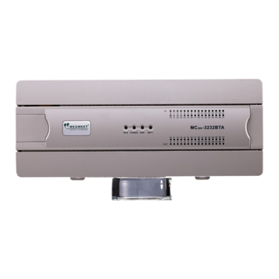
1. Appearance and Part Names
Fig. 1-1 Appearance and part name
2. Installation Description
2.1 Installation method
DIN rail mounting
Generally, you can mount the PLC onto a 35mm-wide rail (DIN). Open
the DIN snap-fit at the bottom of the module and lock the bottom of the
module onto the DIN rail; Rotate module close to the DIN guide rail and close
the DIN snap-fit with a double-checking.
Screw fixing
Fixing the PLC with screws can stand greater shock than DIN rail
mounting. M3 screws can be chosen to fix the PLC onto the backboard of the
electric cabinet through the mounting holes on PLC enclosure, as the
following figure.
Software
User
Manual ,
and
2.2 Cable connection and specification
It is recommended to use stranded copper cables and prefabricate
insulated plugs to ensure connection quality. The following table lists the
sectional areas and models of the recommended cables.
Recommended
Cable
NO.
AC power line
AWG12/AWG18
(L、N)
Ground
AWG12
line
Input signal
AWG18/AWG20
(X)
Output signal
AWG18/AWG20
(Y)
Fix the prepared cable head onto the PLC terminals with screws
correctly. Fastening torque: 0.5~0.8Nm.
◆For the safety (to prevent electric shock and fire accidents) and lower
noise, the ground terminal of the controller should be connected in
accordance with the requirements from national electrical regulations, and
the ground resistance should be less than 100 Ω . Single point grounding
should be used when wiring multiple controllers, and the ground wire cannot
form a loop. As shown in the diagram below:
×
Note for wiring:
1. It is recommended to use a shielded twisted-pair cable for thermal
resistance input. The cable should be far away from power cable or other
cables that may generate electrical power interference.
2. The thermal resistance sensor should use 3-wire system for a
ascending measurement precision. In order to reduce measurement errors
and avoid noise interference, it is recommended to use a connection line
within 100m.
Terminal and heat shrink
Cross-Section
tubing
H1.5/14 prefabricate
1.0—2.0mm
2
insulated tubing terminal, or
Wire end tinning treatment
H2.0/14 prefabricate
2.0mm
2
insulated tubing terminal, or
Wire end tinning treatment
0.8—1.0mm
2
UT1-3 or OT1-3 cold-pressed
terminal, Φ3 or Φ4 heat
shrink tubing
0.8—1.0mm
2
√
Advertisement
Table of Contents

Related Manuals for Megmeet MC200 Series


Summary of Contents for Megmeet MC200 Series
- Page 1 MC200-2PT Thermal Resistance Module User Quick Start Manual Thank you for using MC200 series PLC. Before using the product, please carefully read this manual so as to better understand it, fully use it, and ensure safety. This quick start manual is to offer you a quick guide to the design, installation, connection and maintenance of MC200 series PLC, convenient for on-site reference.
-
Page 2: Technical Specification
3. If there is too much external interference, connect the shield ground Pt100 0.2°C 0.36°F FG to the grounding PG. Resolution Cu100 0.2°C 0.36°F Cu50 0.2°C 0.36°F 4. The analog power supply can use the auxiliary output 24Vdc power Accuracy ±1% of full range supply of the main module, or other required power supply. -
Page 3: Application Example
6. Application Example Example: The address of the MC200-2PT module is 0 (for the addressing method of the special module, refer to MC200 Series PLC User Manual). Connect the CH1 of MC200-2PT module to Pt100 thermal resistance to output Celsius data, CH2 to Cu100 thermal resistance to output Celsius data, CH3 to Cu50 to output Fahrenheit data, and close the CH4. -
Page 4: Buffer Memory (Bfm)
7. Buffer Memory (BFM) Table 7-2 describes the meanings of x. The conversion time for each channel is 15ms, and when a channel is set to close, the corresponding MC200-2PT exchanges data with the main module through BFM. The channel does not perform A/D conversion, reducing the total conversion time. main module uses TO command to write data into the BFM to configure Table 7-2 Meanings of x MC200-2PT, and uses FROM command to read AD conversion result and... -
Page 5: Routine Inspection
12. BFM#4095 is module ID. ID of MC200-2PT is H5022. The user program characteristics characteristics setting data in characteristics in PLC can use this ID to identify the module before transmitting/receiving setting error BFM or adjustment error setting normal data. b2: power supply Power supply 24Vdc power supply failed... - Page 6 Notice 1. The warranty range is confined to the PLC only. 2. Warranty period is 18 months, within which period Megmeet conducts free maintenance and repairing to the PLC that has any fault or damage under the normal operation conditions.
Need help?
Do you have a question about the MC200 Series and is the answer not in the manual?
Questions and answers