Advertisement
MC200-2DA Analog Quantity Output Module
User Quick Start Manual
Thank you for using MC200 series PLC. Before using the product,
please carefully read this manual so as to better understand it, fully use it,
and ensure safety. This quick start manual is to offer you a quick guide to the
design, installation, connection and maintenance of MC200 series PLC,
convenient for on-site reference.
This manual is for the following MC200 series members:
MC200-2DA
Analog Quantity Output Module
Version:V1.1
Revision Date:2010-04-01
BOM Code:R29090044
For detailed product information, please refer to MC200 Series PLC
User Manual , X-Builder Programming Software User Manual , and MC200/
MC100 Series PLC Programming Reference Manual . For ordering the above
user manuals, contact your Megmeet distributor or sales office.
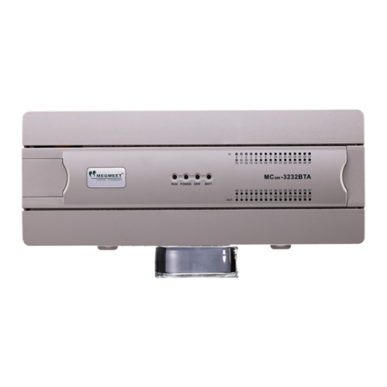
1. Appearance and Part Names
Fig. 1-1 Appearance and part name
2. Installation Description
2.1 Installation method
DIN rail mounting
Generally, you can mount the PLC onto a 35mm-wide rail (DIN). Open
the DIN snap-fit at the bottom of the module and lock the bottom of the
module onto the DIN rail; Rotate module close to the DIN guide rail and close
the DIN snap-fit with a double-checking.
Screw fixing
Fixing the PLC with screws can stand greater shock than DIN rail
mounting. M3 screws can be chosen to fix the PLC onto the backboard of the
electric cabinet through the mounting holes on PLC enclosure, as the
following figure.
Fig. 2-2 Screw installation diagram
2.2 Cable connection and specification
It is recommended to use stranded copper cables and prefabricate
insulated plugs to ensure connection quality. The following table lists the
sectional areas and models of the recommended cables.
Recommended
Cable
NO.
AC power line
AWG12/AWG18
(L、N)
AWG12
Ground line
Input signal (X)
AWG18/AWG20
Output signal
AWG18/AWG20
(Y)
Fix the prepared cable head onto the PLC terminals with screws
correctly. Fastening torque: 0.5~0.8Nm.
◆For the safety (to prevent electric shock and fire accidents) and lower
noise, the ground terminal of the controller should be connected in
accordance with the requirements from national electrical regulations, and
the ground resistance should be less than 100 Ω . Single point grounding
should be used when wiring multiple controllers, and the ground wire cannot
form a loop. As shown in the diagram below:
×
Note for wiring:
1. It is recommended to use a shielded twisted-pair cable for analog
input. The cable should be far away from power cable or other cables that
may generate electrical power interference.
2. If there is interference in the external electrical wiring and the input
signal fluctuates, you can connect a smoothing capacitor (0.1μF ~ 0.47 μF
/25V).
3. If the current channel uses the current input mode, short-circuit the
voltage input terminal and the current input terminal.
Terminal and heat shrink
Cross-Section
tubing
H1.5/14 prefabricate
1.0—2.0mm
2
insulated tubing terminal, or
Wire end tinning treatment
H2.0/14 prefabricate
2.0mm
2
insulated tubing terminal, or
Wire end tinning treatment
0.8—1.0mm
2
UT1-3 or OT1-3 cold-pressed
terminal, Φ3 or Φ4 heat
0.8—1.0mm
2
shrink tubing
√
Advertisement
Table of Contents

Subscribe to Our Youtube Channel
Related Manuals for Megmeet MC200 Series


Summary of Contents for Megmeet MC200 Series
- Page 1 MC200-2DA Analog Quantity Output Module User Quick Start Manual Thank you for using MC200 series PLC. Before using the product, please carefully read this manual so as to better understand it, fully use it, and ensure safety. This quick start manual is to offer you a quick guide to the design, installation, connection and maintenance of MC200 series PLC, Fig.
-
Page 2: Technical Specification
4. Terminal Introduction 4. The analog power supply can use the auxiliary output 24Vdc power Table 4-1 describes the definitions of MC200-2DA terminals. supply of the main module, or other required power supply. 5. Grounding terminal PG of the module is well grounded. Remark Description 24V+... -
Page 3: Buffer Memory (Bfm)
Example: The MC200-2DA module address is 1 (for the addressing of #902 CH1-D1 Default: 2000 (input mode 0) expansion modules, refer to the MC200 Series PLC User Manual ). Set the #903 CH1-A1 Default: 10000 (input mode 0) channel 1 to voltage input (-10V~10V), CH2 to current input (4mA~20mA). -
Page 4: Routine Inspection
2. BFM#650: output mode selection. It adopts 4 hexadecimal digits H×4× 7. Setting BFM#400 to 1 will restore all module settings to default values. 3 × 2 × 1, where × 1 and × 2 are respectively the commands for channel 1, 8. - Page 5 Notice 1. The warranty range is confined to the PLC only. 2. Warranty period is 18 months, within which period Megmeet conducts free maintenance and repairing to the PLC that has any fault or damage under the normal operation conditions.
Need help?
Do you have a question about the MC200 Series and is the answer not in the manual?
Questions and answers