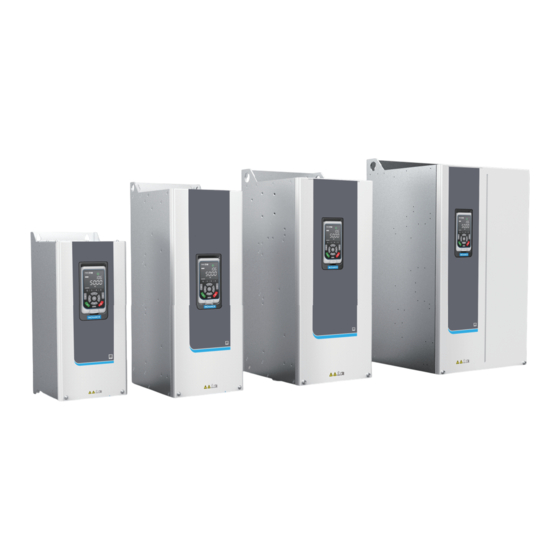
Inovance MD580 Series Maintenance Manual
Low-voltage high-performance engineering ac drive(690 v)
Hide thumbs
Also See for MD580 Series:
- Hardware manual (184 pages) ,
- Installation manual (167 pages) ,
- Installation manual (105 pages)
Table of Contents
Advertisement
Quick Links
Advertisement
Table of Contents

Related Manuals for Inovance MD580 Series


Summary of Contents for Inovance MD580 Series
-
Page 2: Preface
Preface Preface Introduction The MD580 series is a low‑voltage high‑performance engineering AC drive (690 V) that can control permanent magnet synchronous motors and AC asynchronous motors. Adopting the high‑performance vector control technology, the MD580 series features high torque output at a low speed, excellent dynamic characteristics, superior overload capabilities, and stable performance. - Page 3 (such as sulfide gas, acid gas, conductive dust, etc.) or with high humidity. The maintenance fee is charged according to the latest Maintenance Price List of Inovance. If otherwise agreed upon, the agreed terms and conditions shall prevail. ‑...
-
Page 4: Table Of Contents
Table of Contents T T a a b b l l e e o o f f C C o o n n t t e e n n t t s s Preface ................1 Fundamental Safety Instructions . -
Page 5: Fundamental Safety Instructions
● requirements; otherwise, a fault may occur. Noncompliance‑caused malfunction or damage to parts are not covered in product quality warranty. Inovance shall take no responsibility for any personal injuries or property damage ● caused by improper usage. Safety Levels and Definitions Indicates that failure to comply with the notice can result in death or severe personal injuries. - Page 6 Fundamental Safety Instructions Unpacking Do not install the equipment if you find damage, rust, or indications of use on the ● equipment or accessories. Do not install the equipment if you find water seepage, component missing or damage ● upon unpacking. Do not install the equipment if you find the packing list does not conform to the ●...
- Page 7 Fundamental Safety Instructions Installation Installation must be carried out by the specialists who have received the necessary ● electrical training and understood Ensure no unprofessional person has access to the equipment. Read through the guide and safety instructions before installation. ●...
- Page 8 Fundamental Safety Instructions Equipment installation, wiring, maintenance, inspection, or parts replacement must be ● performed by only professionals. Before wiring, cut off all the power supplies of the equipment. Wait as specified on the ● product warning sign before further operations because residual voltage exists after power‑off.
- Page 9 Fundamental Safety Instructions Perform a trial run after wiring and parameter setting to ensure that the equipment ● operates safely. Failure to comply may result in personal injuries or equipment damage. Before power‑on, ensure that the nominal voltage of the equipment is consistent with ●...
- Page 10 Fundamental Safety Instructions Submit the repair request according to the warranty agreement. ● When the fuse is blown, the circuit breaker trips, or the earth leakage circuit breaker ● (ELCB) trips, wait for a period specified on the warning label of the device before you energize or operate the device.
-
Page 11: Precautions For Maintenance And Repair
Precautions for Maintenance and Repair Precautions for Maintenance and Repair Precautions for Maintenance and Repair Danger Allow only professional technicians to maintain and repair the AC drive. ● Wait for at least 15 minutes after power‑off and confirm that the DC bus voltage is ●... - Page 12 Precautions for Maintenance and Repair 6. Determine that the equipment is powered off by measuring. Remove or disassemble the shield or other cabinet structures when taking measurements, and act in compliance with local laws and regulations concerning live‑line working (including but not limited to protection against electric shock and arcing). Make sure that the voltage between the drive input terminals (R, S, and T) and ●...
-
Page 13: Maintenance Cycle
Maintenance Cycle Maintenance Cycle To ensure normal use of AC drives for long time, regular maintenance and inspection must be performed on the electronic components inside the drive according to their service life. The general service life of the internal components is listed in the following table. -
Page 14: Routine Maintenance
Routine Maintenance Routine Maintenance Routine Maintenance The AC drive is mostly composed of electrical components. Therefore, it is necessary to inspect and maintain worn electrical components. 3.1.1 Routine Inspection Checklist Perform routine inspection according to the following checklist. Table 3–1 Routine inspection checklist Routine Inspection Item Check whether the AC drive produces abnormal vibration or noise. -
Page 15: Periodic Inspection Checklist
Routine Maintenance Note Ensure that the dust inside the AC drive is cleared regularly and thoroughly by ● qualified professionals in compliance with relevant safety regulations. Clear dust at least once a year (or more frequently, depending on the service ●... -
Page 16: Equipment Ventilation And Cleaning
Routine Maintenance Figure 3‑1 Main circuit insulation test of the MD580 series AC drive (S4) Figure 3‑2 Main circuit insulation test of the MD580 series AC drive (S5 to S9) 3.3.2 Equipment Ventilation and Cleaning Cleaning the Exterior of the AC Drive... - Page 17 Routine Maintenance Dry or damp (non wet) cleaning cloth (moistened with water or a mild ● detergent, pH 5–9 for metals) Prevent water from entering the AC drive to cause damage. Do not use a hose or too much water, and be cautious of steam. Cleaning the Heatsink If not cleaned, the heatsink fins will be blocked, causing the AC drive overheating alarm or fault.
-
Page 18: Parts Replacement
Parts Replacement Parts Replacement The influence of the ambient temperature, humidity, dust, and vibration will cause aging of components inside the AC drive, which may result in potential faults or shorten the service life of the AC drive. Therefore, it is essential to carry out routine and periodic maintenance on the AC drive. -
Page 19: Replacing The Communication Expansion Card
Parts Replacement 2. Unplug the fan terminal. Figure 4‑1 Unplugging the fan terminal 3. Remove the four M4 screws with a screwdriver to disassemble the fan component. Figure 4‑2 Removing the fan 4. Install a new fan of the same specifications in reverse order. Replacing the Communication Expansion Card The steps for replacing the communication expansion card of the S4 to S9 models are exactly the same. -
Page 20: Replacing The Emc Board
Parts Replacement Figure 4‑3 Removing the cover 3. Unplug the terminal, remove one M4 screw with a screwdriver, and disassemble the communication expansion card. Figure 4‑4 Removing the communication expansion card 4. Install a new communication expansion card in reverse order. Replacing the EMC Board To replace the EMC board on an S6 or S7 model, perform the following steps: 1. - Page 21 Parts Replacement Figure 4‑5 Removing the cover 3. Remove the cables connecting to the control circuit terminals ①, ②, ③, and ④ (terminals as shown in the dashed box in " Figure 4–7 Removing control terminal cables " on page 21 ) of the AC drive.
- Page 22 Parts Replacement Figure 4‑7 Removing control terminal cables 4. Remove the six M4 fixing bolts for the control component. Figure 4‑8 Removing the control component 5. Lift the control component and remove the three terminals on the back of the control board.
- Page 23 Parts Replacement Figure 4‑9 Removing the terminals on the back of the control board 6. Remove the six M4 fixing bolts for the control chamber cover. Figure 4‑10 Removing the control chamber cover 7. Remove the seven M4 fixing bolts and two M4 ground bolts for the EMC board. ‑...
- Page 24 3. Remove the cables connecting to the control circuit terminals ①, ②, ③, and ④. For details about the control circuit terminals, see the control circuit terminal description section in the MD580 Series Low‑Voltage High‑Performance Engineering AC Drive Hardware Guide (690 V) .
- Page 25 Parts Replacement Figure 4‑13 Removing control terminals 4. Remove the five M4 fixing bolts for the control board bracket (including the control board and operating panel on the bracket). Figure 4‑14 Removing the control module 5. Lift the control component and remove the four terminals on the back of the control board (marked ①, ②, ③, and ④...
-
Page 26: Replacing The Power Board
Parts Replacement Figure 4‑15 Removing terminals on the back of the control module 6. Remove the seven M4 fixing bolts for the EMC board. Figure 4‑16 Removing the EMC board 7. Install an EMC board of the same specifications in reverse order. Replacing the Power Board To replace the power board on an S6 or S7 model, perform the following steps: 1. - Page 27 Parts Replacement 3. Remove the cables connecting to the control circuit terminals ①, ②, ③, and ④ (terminals as shown in the dashed box in " Figure 4–19 Removing control terminal cables " on page 26 ) of the AC drive. Figure 4‑18 Positions of control terminals Figure 4‑19 Removing control terminal cables 4.
- Page 28 Parts Replacement Figure 4‑20 Removing the control component 5. Lift the control component and remove the three terminals on the back of the control board. Figure 4‑21 Removing the terminals on the back of the control board 6. Remove the six M4 fixing bolts for the control chamber cover. ‑27‑...
- Page 29 Parts Replacement Figure 4‑22 Removing the control chamber cover 7. Remove all terminals of the power board and the five M4 fixing bolts. Figure 4‑23 Removing the power board 8. Install a power board of the same specifications in reverse order. To replace the power board on an S8 or S9 model, perform the following steps: 1.
- Page 30 3. Remove the cables connecting to the control circuit terminals ①, ②, ③, and ④. For details about the control circuit terminals, see the control circuit terminal description section in the MD580 Series Low‑Voltage High‑Performance Engineering AC Drive Hardware Guide (690 V) .
- Page 31 Parts Replacement Figure 4‑26 Removing the control module 5. Lift the control component and remove the four terminals on the back of the control board. Figure 4‑27 Removing terminals on the back of the control module 6. Remove all terminals of the power board and the five M4 fixing bolts. Figure 4‑28 Removing the power board 7.
-
Page 32: Replacing The Drive Board
Parts Replacement Replacing the Drive Board To replace the drive board on an S5 model, perform the following steps: 1. Take electrical safety precautions before operation by referring to " Precautions for Maintenance and Repair " on page 10 2. Remove the two M4 bolts fixing the cover of the AC drive and lift the cover. Figure 4‑29 Removing the cover 3. - Page 33 Parts Replacement Figure 4‑31 Removing control terminal cables 4. Remove the six M4 fixing bolts for the control component. Figure 4‑32 Removing the control component 5. Lift the control component and remove the three terminals on the back of the control board.
- Page 34 Parts Replacement Figure 4‑33 Removing the terminals on the back of the control board 6. Remove the six M4 fixing bolts for the control chamber cover. Figure 4‑34 Removing the control chamber cover 7. Remove all terminals of the drive board as well as the four M4 fixing bolts and three plastic hexagonal prisms.
- Page 35 Parts Replacement Figure 4‑35 Removing the drive board 8. Install a drive board of the same specifications and the plastic hexagonal prisms in reverse order. ‑ ‑...
-
Page 36: Storage And Warranty
Warranty Free warranty covers only the AC drive itself. Inovance provides an 18‑month warranty (subject to the barcode on the AC drive or contract if there is any) to the equipment from the date of shipment for the failure or damage under normal use conditions. -
Page 37: Disposal And Recycle
Disposal and Recycle Disposal and Recycle Contact a qualified electronic and electrical waste equipment disposal company to recycle and dispose of the retired equipment and dispose of it according to local regulations. ‑ ‑... - Page 38 *19012182A00*...
Need help?
Do you have a question about the MD580 Series and is the answer not in the manual?
Questions and answers