Table of Contents
Advertisement
Quick Links
VISIT VIKINGPUMP.COM FOR PDF OF CURRENT TSM ISSUE & TO VIEW REPAIR VIDEOS
TECHNICAL SERVICE MANUAL: INSTALLATION, OPERATION & MAINTENANCE
TABLE OF CONTENTS
Model Number Chart ...............................................................1
Safety Information & Instructions ..........................................2
Risk assessment .........................................................................3
Introduction ..............................................................................4
General .......................................................................................4
Viking Pump Hygienic Distributors .............................................4
Receipts & Storage .....................................................................4
Cleaning ......................................................................................5
ATEX Information ........................................................................5
ATEX Pump Requirements .................................................5
Equipment Groups & Categories ........................................5
Pump Model & Serial Number ....................................................6
Standard Pump Component Terms ............................................6
General ......................................................................................7
SteriLobe Pumping Principle ......................................................7
Rotary Lobe Pump Principle .......................................................7
System Design & Installation ......................................................7
Installation with CIP Systems ............................................10
Start Up Procedure ...................................................................10
Shutdown Procedure ................................................................10
Routine Maintenance - Non Atex units ....................................11
Additional Routine Maintenance - Atex units ...........................11
Integral Pressure Relief Valves ................................................11
Setting and Operating Spring Loaded Valves ...................12
Setting and Operating Air Loaded Valve ...........................12
Relief Valve Maximum Dimensions ..........................................14
Bolt-on Drain Front Cover .........................................................15
SteriLobe Pump Dismantling & Assembly ..........................15
Pump Assembly SLA to SLF ....................................................16
Shaft Assembly ..................................................................16
Rolling Torque / Pre-load ...................................................17
Rotorcase Assembly..........................................................17
Rotor Assembly .................................................................18
Setting Front Clearances SLA - SLD................................18
Setting Front Clearance SLE and SLF ..............................18
Foot Assembly ...................................................................19
Timing - Multilobe Rotors Only .........................................19
Gearbox Assembly ............................................................20
Final Assembly ..................................................................20
Pump Assembly SLG ................................................................21
Shaft Assembly ..................................................................21
Rolling Torque / Pre-load ...................................................22
Final Pre-load Assembly ...................................................23
Timing - Multilobe Rotors only ..........................................23
Foot Assembly ...................................................................24
Setting Front Clearance SLG ............................................24
Final Assembly ..................................................................25
Gearbox Assembly ............................................................26
ROTARY LOBE PRODUCT LINE: STAINLESS STEEL
STERILOBE
SIZES: SLAS, SLAL, SLBS, SLBL, SLCS, SLCL,
SLDS, SLDL, SLES, SLEL, SLFS, SLFL, SLGS, SLGL
© 2024 Viking Pump, Inc. • Eastbourne, UK
SERIES
®
Seals ........................................................................................27
General Procedures for Installing Mechanical Seals ...............27
Single Mechanical Seal SLA to SLG ........................................27
Single Flushed Mechanical Seal SLA to SLF...........................29
Single Flushed Mechanical Seal SLG ......................................31
Double Flushed Mechanical Seal SLA, SLB, SLC ..................33
Double Flushed Mechanical Seal SLD to SLG ........................35
Removal of Rotary (Dynamic) Seal Face from Rotor ..............37
General Procedures for Fitting Single O-ring Seals .................37
SLA to SLG Pumps ...................................................................37
Flushed Product Seals Auxiliary Services.........................37
Double Mechanical Seal for High Pressure Flush ...................38
Flush Connections ....................................................................39
Specifications .........................................................................40
Clearance Chart ........................................................................40
Pressure Limitation of Port Types .............................................41
Fasteners & Torque Settings ....................................................42
Pumps fitted with Spiralock threads ..................................43
Lip-Seal Setting Distances .......................................................43
Lubricants ..................................................................................44
Material Specification ................................................................44
Troubleshooting ........................................................................44
Tool List .....................................................................................45
Service History ..........................................................................46
Notes .........................................................................................47
MODEL NUMBER CHART
S Size Rotorcase
SLAS
SLBS
SLCS
SLDS
SLES
SLFS
SLGS
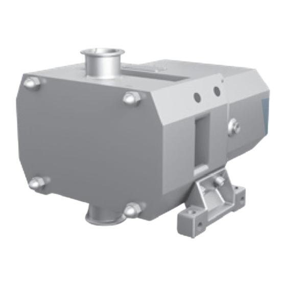
FIGURE 1: SLAS
(SHOWN WITH STANDARD PORTS)
TSM
1725
Page
1 of 48
Issue
A
L Size Rotorcase
SLAL
SLBL
SLCL
SLDL
SLEL
SLFL
SLGL
FIGURE 2: SLDL
(SHOWN WITH VERTICAL PORTS)
Advertisement
Table of Contents

Subscribe to Our Youtube Channel
Related Manuals for Viking pump STERILOBE SLAS


Summary of Contents for Viking pump STERILOBE SLAS
-
Page 1: Table Of Contents
Shaft Assembly ..............21 Rolling Torque / Pre-load ...........22 Final Pre-load Assembly ...........23 Timing – Multilobe Rotors only ..........23 Foot Assembly ..............24 Setting Front Clearance SLG ..........24 Final Assembly ..............25 Gearbox Assembly ............26 © 2024 Viking Pump, Inc. • Eastbourne, UK... -
Page 2: Safety Information & Instructions
If slings are used for lifting, they must be safely difference that could cause a spark. and securely attached. TSM 1725 | Issue A | Page 2 of 48 © 2024 Viking Pump, Inc. • Eastbourne, UK... -
Page 3: Risk Assessment
RISK ASSESSMENT Risk assessment relating to the use Viking Pump SteriLobe rotary lobe pumps units in potentially explosive atmospheres. Note: For a feature to be suitable for an application, the feature must be fit for its designated purpose and also suitable for the environment where it is to be installed. -
Page 4: Introduction
(see image below). The illustrations used in this manual are for identification purposes only and cannot be used for ordering parts. Obtain a parts list from your Viking Pump ® representative. Always give a complete name of part, part number and material with the model number and serial number of pump when ordering repair parts. -
Page 5: Cleaning
Only use genuine spare parts that have been designed and CIP (Clean In Place) and SIP (Sterilisation In Place) refer to verified Atex compliant by Viking Pump Hygienic, failure to "Installation with CIP Systems" on page 10. use genuine spare parts will invalidate the Atex certification. -
Page 6: Pump Model & Serial Number
PUMP MODEL & SERIAL NUMBER FIGURE 3 Should you require any information regarding your rotary lobe pump contact Viking Pump or your Viking Pump Hygienic distributor, providing the pump model and serial number as stated on the pump nameplate, which is fixed to the pump gearbox cover. -
Page 7: General
The Net Positive Suction Head available (NPSHa) from the system must always exceed the Net Positive Suction Head required (NPSHr) by the pump. TSM 1725 | Issue A | Page 7 of 48 © 2024 Viking Pump, Inc. • Eastbourne, UK... - Page 8 Ensure all components are correctly grounded. Suction Line Suction Line Friction Loss Friction Loss Vapor Vapor Pressure Pressure Atmospheric Vacuum TSM 1725 | Issue A | Page 8 of 48 © 2024 Viking Pump, Inc. • Eastbourne, UK...
- Page 9 Dimension L 1500 1.378 2.598 3.071 3.543 4.488 4.961 5.512 6.299 7.283 8.268 9.646 10.630 11.614 13.386 14.764 16.732 18.701 ± 0.039" TSM 1725 | Issue A | Page 9 of 48 © 2024 Viking Pump, Inc. • Eastbourne, UK...
-
Page 10: Installation With Cip Systems
Operating Spring Loaded Valves" on page 12 and 15 and "Seals" on page 27. "Setting and Operating Air Loaded Valve" on page 12. TSM 1725 | Issue A | Page 10 of 48 © 2024 Viking Pump, Inc. • Eastbourne, UK... -
Page 11: Routine Maintenance - Non Atex Units
Atex environment. A general overhaul must include a full disassembly of all components and the following work carried out. TSM 1725 | Issue A | Page 11 of 48 © 2024 Viking Pump, Inc. • Eastbourne, UK... -
Page 12: Setting And Operating Spring Loaded Valves
(123) which will lift the valve head (112). under vacuum, the application of the valve should be To resume normal relief valve operation, exhaust the referred to Viking Pump or Viking Pump Hygienic distributor. Cylinder (123). The selection, setting and application of integral relief... - Page 13 Manual Lift SLA - E Typical FIGURE 12 Spring Loaded Integral Pressure Relief Valve with Airlift SLA – E Typical FIGURE 14 TSM 1725 | Issue A | Page 13 of 48 © 2024 Viking Pump, Inc. • Eastbourne, UK...
-
Page 14: Relief Valve Maximum Dimensions
Diameter Extension Diameter Extension Diameter Extension SLAS SLAL SLBS SLBL SLCS SLCL SLDS SLDL SLES SLEL SLFS SLFL All Dimensions in mm. TSM 1725 | Issue A | Page 14 of 48 © 2024 Viking Pump, Inc. • Eastbourne, UK... -
Page 15: Bolt-On Drain Front Cover
All fasteners are required to be tightened to the required torque setting during assembly, refer to "Fasteners & Torque Settings" on page 42. TSM 1725 | Issue A | Page 15 of 48 © 2024 Viking Pump, Inc. • Eastbourne, UK... -
Page 16: Pump Assembly Sla To Slf
(See "Figure 22ii" on page 17) The right hand helical gear will have the letter ‘D’ stamped on the face. TSM 1725 | Issue A | Page 16 of 48 © 2024 Viking Pump, Inc. • Eastbourne, UK... -
Page 17: Rolling Torque / Pre-Load
(4.01) and use the bolts (4.08) to secure the rotorcase (3.01) Note: Rolling torque can only be set on new bearings, with no sealing devices installed i.e. lip-seals or O-rings. TSM 1725 | Issue A | Page 17 of 48 © 2024 Viking Pump, Inc. • Eastbourne, UK... -
Page 18: Rotor Assembly
Tab Washer clearances Note: When assembling the pump with a new front clearance spacer the rotor will Be proud of the rotorcase. TSM 1725 | Issue A | Page 18 of 48 © 2024 Viking Pump, Inc. • Eastbourne, UK... -
Page 19: Foot Assembly
• Using feeler gauge to check the mesh clearance in position ‘M’, ensure the rotor is turned in the correct orientation to minimise the mesh clearance. TSM 1725 | Issue A | Page 19 of 48 © 2024 Viking Pump, Inc. • Eastbourne, UK... -
Page 20: Gearbox Assembly
(see tool list FIGURE 36 for details). 4.09 FIGURE 39 4.04 2.02 / 2.03 2.01 TSM 1725 | Issue A | Page 20 of 48 © 2024 Viking Pump, Inc. • Eastbourne, UK... -
Page 21: Pump Assembly Slg
TSM 1725 | Issue A | Page 21 of 48 © 2024 Viking Pump, Inc. • Eastbourne, UK... -
Page 22: Rolling Torque / Pre-Load
(4.10) Note: When machining the spacer make sure small cuts are taken i.e. 0.02mm – 0.03 Viking Pump does offer a shim set if the spacer has been machined too small (5.26) FIGURE 50 • Install the bearing cone (5.03) and the bearing retainer plate (5.05) secure using the screws (5.20) see "Figure... -
Page 23: Final Pre-Load Assembly
(5.06), tab washer (5.08) and locknut (5.09) – See "Fasteners & Torque Settings" on page 42 for torque settings FIGURE 55 5.09 5.07 5.08 5.06 TSM 1725 | Issue A | Page 23 of 48 © 2024 Viking Pump, Inc. • Eastbourne, UK... -
Page 24: Foot Assembly
(See "Fasteners & Torque Settings" on page 42 for torque settings) TSM 1725 | Issue A | Page 24 of 48 © 2024 Viking Pump, Inc. • Eastbourne, UK... -
Page 25: Final Assembly
• When the front clearance spacer has been machined to the correct width make sure that the spacer kept with the respective shaft. TSM 1725 | Issue A | Page 25 of 48 © 2024 Viking Pump, Inc. • Eastbourne, UK... -
Page 26: Gearbox Assembly
Note: Before re-assembling the rotorcase refer to "Seals" on page 27 for instructions • Install the guard (7.03) onto the rear of the rotorcase (3.01) TSM 1725 | Issue A | Page 26 of 48 © 2024 Viking Pump, Inc. • Eastbourne, UK... -
Page 27: Seals
(See "Fasteners & Torque Settings" on page 42 for torque settings) FIGURE 74 8.02 8.08 FIGURE 73 8.04 8.09 8.01 8.06 1.01 8.07 8.03 8.05 1.03 TSM 1725 | Issue A | Page 27 of 48 © 2024 Viking Pump, Inc. • Eastbourne, UK... - Page 28 (8.07) FIGURE 80 FIGURE 81 8.06 / 8.07 • Install the slinger (5.15) 8.06 TSM 1725 | Issue A | Page 28 of 48 © 2024 Viking Pump, Inc. • Eastbourne, UK...
-
Page 29: Single Flushed Mechanical Seal Sla To Slf
L-cup. The seals are now assembled. 8.09 For rotor and front cover installation see "SteriLobe Pump Dismantling & Assembly" on page 15. TSM 1725 | Issue A | Page 29 of 48 © 2024 Viking Pump, Inc. • Eastbourne, UK... - Page 30 • Install the O-ring (8.19) onto the sleeve (8.20) and then install the sleeve onto the shaft and secure with the grub screws (8.14) 7.03 3.01 FIGURE 89 8.20 8.19 4.08 TSM 1725 | Issue A | Page 30 of 48 © 2024 Viking Pump, Inc. • Eastbourne, UK...
-
Page 31: Single Flushed Mechanical Seal Slg
The cut out in the seal face should be lined up with the cut out in the L-cup. TSM 1725 | Issue A | Page 31 of 48 © 2024 Viking Pump, Inc. • Eastbourne, UK... - Page 32 (3.01) that the location slots line up with the pins in the seal housing FIGURE 101 FIGURE 104 8.04 8.03 3.01 7.03 TSM 1725 | Issue A | Page 32 of 48 © 2024 Viking Pump, Inc. • Eastbourne, UK...
-
Page 33: Double Flushed Mechanical Seal Sla, Slb, Slc
FIGURE 107 5.15 Note: Depending on the seal arrangement the slinger will fit on the shaft or the rear half of the seal. TSM 1725 | Issue A | Page 33 of 48 © 2024 Viking Pump, Inc. • Eastbourne, UK... - Page 34 8.04 8.03 4.08 • Install the L-cup (8.01) and the rotary face (8.02) into the rotor (2.01) FIGURE 115 2.01 8.01 8.02 TSM 1725 | Issue A | Page 34 of 48 © 2024 Viking Pump, Inc. • Eastbourne, UK...
-
Page 35: Double Flushed Mechanical Seal Sld To Slg
8.13 Note: There are two drive slots in the shaft which must be lined up with the drive pins on the sleeve. TSM 1725 | Issue A | Page 35 of 48 © 2024 Viking Pump, Inc. • Eastbourne, UK... - Page 36 The seals are now assembled. the rotorcase. For rotor and front cover installation see "SteriLobe Pump FIGURE 123.5 Dismantling & Assembly" on page 15. 8.24 8.25 TSM 1725 | Issue A | Page 36 of 48 © 2024 Viking Pump, Inc. • Eastbourne, UK...
-
Page 37: Removal Of Rotary (Dynamic) Seal Face From Rotor
WARNING Note: Do not run an O-ring seal dry. TSM 1725 | Issue A | Page 37 of 48 © 2024 Viking Pump, Inc. • Eastbourne, UK... -
Page 38: Single Mechanical Seal For Low-Pressure Quench Or Flush
"Flush Connections" on page 39. The pipe work should be arranged to provide an independent flush to each seal. TSM 1725 | Issue A | Page 38 of 48 © 2024 Viking Pump, Inc. • Eastbourne, UK... -
Page 39: Flush Connections
22.2 SLBS 23.5 SLBL 28.2 SLCS 66.5 42.5 SLCL SLDS 30.5 57.5 SLDL 40.5 SLES SLEL SLFS SLFL SLGS 69.8 SLGL 69.8 TSM 1725 | Issue A | Page 39 of 48 © 2024 Viking Pump, Inc. • Eastbourne, UK... -
Page 40: Specifications
1.77 2.56 1.38 2.36 1.77 SLGL BW 3.94 4.72 1.77 2.56 1.38 2.36 1.77 Note: ML = Multilobe | BW = Bi-wing TSM 1725 | Issue A | Page 40 of 48 © 2024 Viking Pump, Inc. • Eastbourne, UK... -
Page 41: Pressure Limitation Of Port Types
PRESSURE LIMITATION OF PORT TYPES TSM 1725 | Issue A | Page 41 of 48 © 2024 Viking Pump, Inc. • Eastbourne, UK... -
Page 42: Fasteners & Torque Settings
M10 x 25 Socket Head Cylinder 9.16 — — — — — — Cap Screw / Front Torque N/m Cover Torque lbf ft 33.2 TSM 1725 | Issue A | Page 42 of 48 © 2024 Viking Pump, Inc. • Eastbourne, UK... -
Page 43: Pumps Fitted With Spiralock Threads
Spiralock thread please contact your Viking Pump Hygienic Distributor. TSM 1725 | Issue A | Page 43 of 48 © 2024 Viking Pump, Inc. • Eastbourne, UK... -
Page 44: Lubricants
Increase Pump Speed Seal Flush Inadequate Increase Seal Flush To Required Pressure / Flow Bearing / Timing Gear Wear Replace Worn Components TSM 1725 | Issue A | Page 44 of 48 © 2024 Viking Pump, Inc. • Eastbourne, UK... -
Page 45: Tool List
Diameter 13 - 400 Tommy Bar ● long Diameter 16 - 600 ● ● long Pin Spanner ● ● ● ● ● TSM 1725 | Issue A | Page 45 of 48 © 2024 Viking Pump, Inc. • Eastbourne, UK... -
Page 46: Service History
SERVICE HISTORY Pump Model: Pump Serial No: DATE COMMENTS TSM 1725 | Issue A | Page 46 of 48 © 2024 Viking Pump, Inc. • Eastbourne, UK... -
Page 47: Notes
NOTES TSM 1725 | Issue A | Page 47 of 48 © 2024 Viking Pump, Inc. • Eastbourne, UK... - Page 48 (www.vikingpump.com/warranty#information). complete copy of the warranty may also be obtained by contacting Viking through regular mail at Viking Pump, Inc., 406 State Street, Cedar Falls, Iowa 50613, USA. THIS WARRANTY IS AND SHALL BE VIKING’S SOLE AND EXCLUSIVE WARRANTY AND IS IN LIEU OF...
Need help?
Do you have a question about the STERILOBE SLAS and is the answer not in the manual?
Questions and answers