Table of Contents
Advertisement
Quick Links
Warranty
All products manufactured by ICP DAS are warranted
against defective materials for a period of one year from
the date of delivery to the original purchaser.
Warning
ICP DAS assume no liability for damages consequent
to the use of this product. ICP DAS reserves the right to
change this manual at any time without notice. The
information furnished by ICP DAS is believed to be
accurate and reliable. However, no responsibility is
assumed by ICP DAS for its use, nor for any infringements
of patents or other rights of third parties resulting from its
use.
Copyright
Copyright 2007 by ICP DAS. All rights are reserved.
Trademark
The names used for identification only maybe
registered trademarks of their respective companies.
PISO-CM100 User's Manual
PISO-CM100-D/T
User's Manual
(Ver :1.00 11/27/07)
1
Advertisement
Chapters
Table of Contents
Troubleshooting

Related Manuals for ICP DAS USA PISO-CM100-D


Summary of Contents for ICP DAS USA PISO-CM100-D
- Page 1 PISO-CM100-D/T User’s Manual Warranty All products manufactured by ICP DAS are warranted against defective materials for a period of one year from the date of delivery to the original purchaser. Warning ICP DAS assume no liability for damages consequent to the use of this product. ICP DAS reserves the right to change this manual at any time without notice.
-
Page 2: Table Of Contents
2.3.1 5-pin screw terminal connector ........12 2.3.2 9-pin D-sub male connectors .........13 2.3.3 Wire connection ..............14 LED Indicator & PISO-CM100-D/T Mode ........15 Hardware Installation..............16 Driver Introduction ................17 Software Installation..............17 Software Architecture..............22 APIs for Windows Application .............25 Windows API Definitions and Descriptions.......25 4.1.1... - Page 3 4.1.18 CM100_Check186Mode...........44 4.1.19 CM100_Status..............45 4.1.20 CM100_AddCyclicTxMsg ..........47 4.1.21 CM100_DeleteCyclicTxMsg ..........49 4.1.22 CM100_EnableCyclicTxMsg ...........50 4.1.23 CM100_DisableCyclicTxMsg ..........51 4.1.24 CM100_OutputByte ............52 4.1.25 CM100_InputByte ............53 4.1.26 CM100_ClearSoftBuffer ....54 <For default firmware> 4.1.27 CM100_ClearBufferStatus ....55 <For default firmware> 4.1.28 CM100_ClearDataOverrun ....56 <For default firmware> 4.1.29 CM100_Config ........57...
- Page 4 5.1.3 L2Off .................90 5.1.4 L2On .................90 5.1.5 DPRAMInttToHost ............91 5.1.6 UserDPRAMIrqFunc ......92 <must be called once > 5.1.7 DPRAMWriteByte ............93 5.1.8 DPRAMWriteWord ............94 5.1.9 DPRAMWriteDword ............95 5.1.10 DPRAMWriteMultiByte ............96 5.1.11 DPRAMReadByte.............97 5.1.12 DPRAMReadWord ............98 5.1.13 DPRAMReadDword ............99 5.1.14 DPRAMReadMultiByte ..........100 5.1.15 DPRAMMemset..............101 5.1.16...
- Page 5 5.1.41 GetCANBaud..............129 5.1.42 SetCANMask ..............130 5.1.43 GetCANMask..............132 5.1.44 CANConfig ..............133 5.1.45 EnableSJA1000..............134 5.1.46 DisableSJA1000.............134 5.1.47 GetCANStatus..............135 5.1.48 ClearDataOverrunStatus..........136 5.1.49 SendCANMsg..............137 5.1.50 ClearTxSoftBuffer............138 5.1.51 GetCANMsg ..............139 5.1.52 ClearRxSoftBuffer ............141 5.1.53 RxMsgCount ..............141 5.1.54 AddCyclicTxMsg ............142 5.1.55 DeleteCyclicTxMsg............143 5.1.56 EnableCyclicTxMsg............144 5.1.57 DisableCyclicTxMsg............145 5.1.58 ResetCyclicTxBuf............145 5.1.59...
-
Page 6: General Information
General Information Introduction The CAN (Controller Area Network) is a serial communication protocol, which efficiently supports distributed real-time control with a very high level of security. It is especially suited for networking "intelligent" devices as well as sensors and actuators within a system or sub-system. In CAN networks, there is no addressing of subscribers or stations in the conventional sense, but instead prioritized messages are transmitted. -
Page 7: Features
Features 33MHz 32bit 5V PCI bus (V2.1) plug and play technology Follow ISO11898-2 specification Philip SJA1000T CAN controller Philip 82C250 CAN transceiver CAN controller frequency :16 MHz 2500Vrms photo-isolation protection on CAN side Jumper select 120Ω terminator resistor for CAN bus One CAN communication port Compatible with CAN specification 2.0 parts A and B Provide default baud 10Kbps, 20Kbps, 50Kbps, 125Kbps, 250Kbps,... -
Page 8: Specifications
Specifications CAN controller: Phillips SJA1000T CAN controller frequency :16 MHz CAN transceiver: Phillips 82C250. Follow ISO11898-2 specification One CAN communication port Compatible with CAN specification 2.0 parts A and B Jumper select 120Ω terminator resistor for CAN bus Provide default baud 10Kbps, 20Kbps, 50Kbps, 125Kbps, 250Kbps, 500Kbps, 800Kbps, and 1Mbps Allow user-defined baud Connector: 5-pin screw terminal connector or 9-pin D-sub male... -
Page 9: Product Check List
Product Check List Besides this manual, the package includes the following items: PISO-CM100 CAN card Software CD ROM Quickstart One debug cable (model number is 4PCA-0904) It is recommended that users read the release note first. All the important information needed will be provided in the release note as following: Where you can find the software driver, utility and demo programs. -
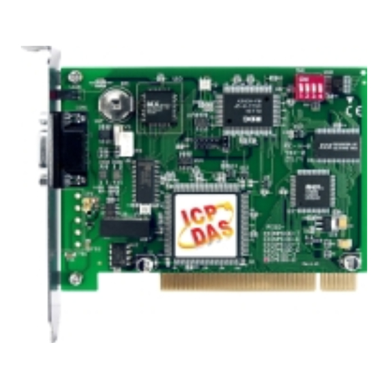
Page 10: Hardware Configuration
Note: PISO-CM100-T layout is similar with PISO-CM100-D. The only difference is the position of CAN port connector. The positions of jumper or DIP switch are the same. Therefore, users can also refer to the PISO-CM100-D layout to configure the jumper or DIP switch if they use PISO-CM100-T. -
Page 11: Jumper Selection
Enable Disable Reset pin for download error. If users want to update firmware but the process is fail, users can enable this jumper to reset the PISO-CM100-D/T Enable Disable into download mode. Debug port for user-defined firmware. Users can connect the debug port with... -
Page 12: Connector Pin Assignment
Connector Pin Assignment The PISO-CM100-T is equipped with one 5-pin screw terminal connector and the PISO-CM100-D is equipped with one 9-pin D-sub male connector for wire connection of the CAN bus. The connector’s pin assignment is specified as following: 2.3.1 5-pin screw terminal connector The 5-pin screw terminal connector of the CAN bus interface is shown in Figure 2.2. -
Page 13: 9-Pin D-Sub Male Connectors
2.3.2 9-pin D-sub male connectors The 9-pin D-sub male connector of the CAN bus interface is shown in Figure 2.3 and the corresponding pin assignments are given in Table 2.3. Figure2.3 9-pin D-sub male connector Pin No. Signal Description No use CAN_L CAN_L bus line (dominant low) No use... -
Page 14: Wire Connection
2.3.3 Wire connection In order to minimize the reflection effects on the CAN bus line, the CAN bus line has to be terminated at both ends by two terminal resistances as in the following figure. According to the ISO 11898-2 spec, each terminal resistance is 120Ω... -
Page 15: Led Indicator & Piso-Cm100-D/T Mode
LED Indicator & PISO-CM100-D/T Mode The LED status will be changed when PISO-CM100-D/T is in different mode. There are three modes, and each mode describes as following: Download mode: In this case, Green LED and red LED will flash once per second. -
Page 16: Hardware Installation
2.1 and table 2.1. 3. Check JP3 and JP4 status of PISO-CM100-D/T. If necessary, enable them. 4. Find an empty PCI slot for the PISO-CM100-D/T on the mother board of the personal computer. Plug the configured PISO-CM100-D/T into this empty PCI slot. -
Page 17: Driver Introduction
The PISO-CM100-D/T can be used in Windows 98/Me/NT/2000/XP environments. Users need to get proper driver for their operation system. These drivers are in Field Bus CD in the PISO-CM100-D/T package. The path is CAN\PCI\PISO-CM100. Also, users can find them from our website as following. - Page 18 The driver installation procedure for Window XP is shown as below: Step1: Execute PISO-CM100.exe file. Then, the installation procedure starts. Step2: Confirm the driver installation path. This may concern with where the demos, debug and utility tools are. PISO-CM100 User’s Manual (Ver :1.00 11/27/07)
- Page 19 Step3: Click Install button to continue. Step4: Afterwards, the files of driver and tools are copied to your disk. PISO-CM100 User’s Manual (Ver :1.00 11/27/07)
- Page 20 Step5: When finishing the installation, the register procedures are running in two consult dialogs. Please wait until these consult dialogs are finished. Step6: If users had installed the driver for PISO-CAN200, PISO-CAN400 or PISO-CM100 series boards. One of register dialog may look like following figure.
- Page 21 Step7: When all procedures are finished, reset your PC to enable the PISO-CM100-D/T driver. PISO-CM100 User’s Manual (Ver :1.00 11/27/07)
-
Page 22: Software Architecture
Software Architecture The basic software architecture of PISO-CM100-D/T is shown in the following figure. The Windows 98/Me/NT/2000/XP APIs for PISO-CM100-D/T are provided by cm100.dll. Users can apply this dll file in VC++, VB and Borland C++ Builder to create the Windows applications. Through the kernel driver, KP_CM100.sys... - Page 23 … and etc. The software architecture is shown below. Figure 3.2 PISO-CM100-D/T Default Firmware Software Architecture Besides, for some special applications, PISO-CM100-D/T provides the flexibilities to arrange the user-defined firmware. This feature may be helpful and powerful for some applications which have complex application protocols or need to improve the system efficiency.
- Page 24 Figure 3.2 PISO-CM100-D/T User-defined Firmware Software Architecture PISO-CM100 User’s Manual (Ver :1.00 11/27/07)
-
Page 25: Apis For Windows Application
APIs for Windows Application In this chapter, the APIs for both default firmware and user-defined firmware are described. The content includes the CM100.dll APIs introductions, error code description and the simple method of troubleshooting. It is helpful to development users’ application. The section 4.1 shows the list and information of all APIs supported by CM100.dll. - Page 26 Function definition Page Note int CM100_AdujstDateTime(BYTE BoardNo) ○△ int CM100_Reset(BYTE BoardNo, BYTE Port) ○△ int CM100_Init(BYTE BoardNo, BYTE Port) ○△ int CM100_HardwareReset(BYTE BoardNo, BYTE Port) ○△ int CM100_Check186Mode(BYTE BoardNo, BYTE *Mode) ○△ int CM100_Status(BYTE BoardNo, BYTE Port, BYTE *bStatus) ○△ int CM100_AddCyclicTxMsg(BYTE BoardNo, BYTE Port, BYTE Mode, DWORD MsgID, BYTE RTR, BYTE DataLen, ○△...
- Page 27 Note: In table 3.1, the mark indicate the valid condition of API ○ △ functions. The function marked by presents that this function ○ △ is useful when the PISO-CM100-D/T is default CM100 firmware inside PISO-CM100 User’s Manual (Ver :1.00 11/27/07)
- Page 28 or user-defined firmware inside respectively. If users use default firmware, all of the functions marked by could be applied. However, ○ if users design their own firmware by using firmware library (firmware library is described in section 3.4), only the functions marked by △...
-
Page 29: Cm100_Getdllversion
4.1.1 CM100_GetDllVersion Description: Obtain the version information of CM100.dll driver. Syntax: WORD CM100_GetDllVersion(void) Parameter: None Return: DLL version information. For example: If 100(hex) is return, it means driver version is 1.00. PISO-CM100 User’s Manual (Ver :1.00 11/27/07) -
Page 30: Cm100_Getboardinf
DWORD *dwDID, DWORD *dwSVID, DWORD *dwSDID, DWORD *dwSAuxID, DWORD *dwIrqNo) Parameter: BoardNo: [input] Switch No of PISO-CM100-D/T, PISO-DNM100-D/T or PISO-CPM100-D/T DIP. The value is form 0 to 15. *dwVID: [output] The address of a variable which is used to receive the vendor ID. -
Page 31: Cm100_Totalboard
Syntax: Int CM100_TotalBoard(void) Parameter: None Return: Return the scanned total board number. 4.1.4 CM100_TotalCM100Board Description: Obtain the total board number of PISO-CM100-D/T installed in the PCI bus. Syntax: Int CM100_TotalCM100Board(void) Parameter: None Return: Return the scanned total PISO-CM100-D/T number. PISO-CM100 User’s Manual... -
Page 32: Cm100_Totaldnm100Board
4.1.5 CM100_TotalDNM100Board Description: Obtain the total board number of PISO-DNM100-D/T installed in the PCI bus. Syntax: Int CM100_TotalDNM100Board(void) Parameter: None Return: Return the scanned total PISO-DNM100-D/T number. 4.1.6 CM100_TotalCPM100Board Description: Obtain the total board number of PISO-CPM100-D/T plugged in the PCI bus. -
Page 33: Cm100_Getcm100Boardswitchno
Int CM100_GetCM100BoardSwitchNo(BYTE BoardCntNo, BYTE *BoardSwitchNo) Parameter: BoardCntNo: [input] The number of specified PISO-CM100-D/T. For example, if the first PISO-CM100-D/T is applied, this value is 0. If the second board is applied, this value is 1. * BoardSwitchNo: [output] The address of a variable used to get the DIP switch No. -
Page 34: Cm100_Getdnm100Boardswitchno
4.1.8 CM100_GetDNM100BoardSwitchNo Description: Obtain the DIP switch No. of PISO-DNM100-D/T. Syntax: Int CM100_GetDNM100BoardSwitchNo(BYTE BoardCntNo, BYTE *BoardSwitchNo) Parameter: BoardCntNo: [input] The number of specified PISO-DNM100-D/T. For example, if the first PISO-DNM100-D/T is applied, this value is 0. If the second board is applied, this value is 1. * BoardSwitchNo: [output] The address of a variable used to get the DIP switch No. -
Page 35: Cm100_Getcpm100Boardswitchno
4.1.9 CM100_GetCPM100BoardSwitchNo Description: Obtain the DIP switch No. of PISO-CPM100-D/T installed in the PCI bus. Syntax: Int CM100_GetCPM100BoardSwitchNo(BYTE BoardCntNo, BYTE *BoardSwitchNo) Parameter: BoardCntNo: [input] The number of specified PISO-DNM100-D/T. For example, if the first PISO-DNM100-D/T is applied, this value is 0. If the second board is applied, this value is 1. * BoardSwitchNo: [output] The address of a variable used to get the DIP switch No. -
Page 36: Cm100_Getcardportnum
Syntax: Int CM100_GetCardPortNum(BYTE BoardNo, BYTE *bGetPortNum) Parameter: BoardNo: [input] Switch No of PISO-CM100-D/T, PISO-DNM100-D/T or PISO-CPM100-D/T DIP. The value is form 0 to 15. * bGetPortNum: [output] The address of a variable used to obtain the port numbers of PISO-CM100-D/T. -
Page 37: Cm100_Activeboard
4.1.11 CM100_ActiveBoard Description: Activate PISO-CM100-D/T. It must be called once before using the other functions of PISO-CM100-D/T APIs. Syntax: int CM100_ActiveBoard(BYTE BoardNo) Parameter: BoardNo: [input] PISO-CM100-D/T DIP switch No. (0~15). Return: CM100_NoError: OK CM100_DriverError: Kernel driver is not opened. CM100_BoardNumberError: BoardNo exceeds the current scanned total board numbers. -
Page 38: Cm100_Closeboard
This method must be called once before exiting the user’s application program. Syntax: int CM100_CloseBoard(BYTE BoardNo) Parameter: BoardNo: [input] PISO-CM100-D/T DIP switch No. (0~15). Return: CM100_NoError: OK CM100_DriverError: Kernel driver is not opened. CM100_BoardNumberError: BoardNo exceeds the current scanned total board numbers. -
Page 39: Cm100_Boardisactive
Description: Obtain the active status of the specific board. Syntax: int CM100_BoardIsActive(BYTE BoardNo) Parameter: BoardNo: [input] PISO-CM100-D/T DIP switch No. (0~15). Return: 0: means the board is inactive. 1: means the board is active. PISO-CM100 User’s Manual (Ver :1.00 11/27/07) -
Page 40: Cm100_ Adujstdatetime
4.1.14 CM100_ AdujstDateTime Description: Adjust date and time of PISO-CM100-D/T by using PC time. Syntax: int CM100_AdujstDateTime(BYTE BoardNo) Parameter: BoardNo: [input] PISO-CM100-D/T DIP switch No. (0~15). Return: CM100_NoError: OK CM100_DriverError: Kernel driver is not opened. CM100_BoardNumberError: BoardNo exceeds the current scanned total board numbers. -
Page 41: Cm100_Reset
Syntax: int CM100_Reset(BYTE BoardNo, BYTE Port) Parameter: BoardNo: [input] PISO-CM100-D/T DIP switch No. (0~15). Port: [input] CAN port No. For PISO-CM100-D/T, this value is always 1. Return: CM100_NoError: OK CM100_DriverError: Kernel driver is not opened. CM100_BoardNumberError: BoardNo exceeds the current scanned total board numbers. -
Page 42: Cm100_Init
Syntax: int CM100_Init(BYTE BoardNo, BYTE Port) Parameter: BoardNo: [input] PISO-CM100-D/T DIP switch No. (0~15). Port: [input] CAN port No. For PISO-CM100-D/T, this value is always 1. Return: CM100_NoError: OK CM100_DriverError: Kernel driver is not opened. CM100_BoardNumberError: BoardNo exceeds the current scanned total board numbers. -
Page 43: Cm100_Hardwarereset
Syntax: int CM100_HardwareReset(BYTE BoardNo, BYTE Port) Parameter: BoardNo: [input] PISO-CM100-D/T DIP switch No. (0~15). Port: [input] CAN port No. For PISO-CM100-D/T, this value is always 1. Return: CM100_NoError: OK CM100_DriverError: Kernel driver is not opened. CM100_BoardNumberError: BoardNo exceeds the current scanned total board numbers. -
Page 44: Cm100_Check186Mode
4.1.18 CM100_Check186Mode Description: Obtain the specified PISO-CM100-D/T if it is in download mode or in firmware mode. Syntax: int CM100_Check186Mode(BYTE BoardNo, BYTE *Mode) Parameter: BoardNo: [input] PISO-CM100-D/T DIP switch No. (0~15). *Mode: [output] The address of a variable used to get the PISO-CM100-D/T mode. -
Page 45: Cm100_Status
CM100_Status(BYTE BoardNo, BYTE Port, BYTE *bStatus) Parameter: BoardNo: [input] PISO-CM100-D/T DIP switch No. (0~15). Port: [input] CAN port No. For PISO-CM100-D/T, this value is always 1. *bStatus: [output] The address of a variable is applied to get the status value of CAN controller. - Page 46 Return: CM100_NoError: OK CM100_DriverError: Kernel driver is not opened. CM100_BoardNumberError: BoardNo exceeds the current scanned total board numbers. CM100_ActiveBoardError: This board is not activated. CM100_PortNumberError: Port number is not correct. PISO-CM100 User’s Manual (Ver :1.00 11/27/07)
-
Page 47: Cm100_Addcyclictxmsg
DWORD TimePeriod, BYTE *Handle) Parameter: BoardNo: [input] PISO-CM100-D/T DIP switch No. (0~15). Port: [input] CAN port No. For PISO-CM100-D/T, this value is always 1. Mode: [input] 0 for 11-bit message ID, 1 for 29-bit message ID. MsgID: [input] CAN message ID. - Page 48 CM100_BoardNumberError: BoardNo exceeds the current scanned total board numbers. CM100_ActiveBoardError: This board is not activated. CM100_PortNumberError: Port number is not correct. CM100_TimeOut: The PISO-CM100-D/T has no response. CM100_SetCyclicMsgFailure: The cyclic transmission messages are over 5 messages or PISO-CM100-D/T replies erroneously.
-
Page 49: Cm100_Deletecyclictxmsg
CM100_DeleteCyclicTxMsg(BYTE BoardNo, BYTE Port, BYTE Handle) Parameter: BoardNo: [input] PISO-CM100-D/T DIP switch No. (0~15). Port: [input] CAN port No. For PISO-CM100-D/T, this value is always 1. Handle: [input] The handle of cyclic transmission message which is obtained by CM100_AddCyclicTxMsg() function. Return: CM100_NoError: OK CM100_DriverError: Kernel driver is not opened. -
Page 50: Cm100_Enablecyclictxmsg
CM100_EnableCyclicTxMsg(BYTE BoardNo, BYTE Port, BYTE Handle) Parameter: BoardNo: [input] PISO-CM100-D/T DIP switch No. (0~15). Port: [input] CAN port No. For PISO-CM100-D/T, this value is always 1. Handle: [input] The handle of cyclic transmission message which is obtained by CM100_AddCyclicTxMsg() function. Return: CM100_NoError: OK CM100_DriverError: Kernel driver is not opened. -
Page 51: Cm100_Disablecyclictxmsg
CM100_DisableCyclicTxMsg(BYTE BoardNo, BYTE Port, BYTE Handle) Parameter: BoardNo: [input] PISO-CM100-D/T DIP switch No. (0~15). Port: [input] CAN port No. For PISO-CM100-D/T, this value is always 1. Handle: [input] The handle of cyclic transmission message which is obtained by CM100_AddCyclicTxMsg() function. Return: CM100_NoError: OK CM100_DriverError: Kernel driver is not opened. -
Page 52: Cm100_Outputbyte
, BYTE Port, WORD wOffset, BYTE bValue) Parameter: BoardNo: [input] PISO-CM100-D/T DIP switch No. (0~15). Port: [input] CAN port No. For PISO-CM100-D/T, this value is always 1. : [input] The register address of SJA1000. wOffset : [input] The value written to the specified register. -
Page 53: Cm100_Inputbyte
Syntax: BYTE CM100_InputByte(BYTE BoardNo, BYTE Port, WORD wOffset) Parameter: BoardNo: [input] PISO-CM100-D/T DIP switch No. (0~15). Port: [input] CAN port No. For PISO-CM100-D/T, this value is always 1. : [input] The register address of SJA1000. wOffset Return: The value read from the specified register. -
Page 54: Cm100_Clearsoftbuffer
Syntax: int CM100_ClearSoftBuffer(BYTE BoardNo, BYTE Port) Parameter: BoardNo: [input] PISO-CM100-D/T DIP switch No. (0~15). Port: [input] CAN port No. For PISO-CM100-D/T, this value is always 1. Return: CM100_NoError: OK CM100_DriverError: Kernel driver is not opened. CM100_BoardNumberError: BoardNo exceeds the current scanned total board numbers. -
Page 55: Cm100_Clearbufferstatus
Syntax: int CM100_ClearBufferStatus(BYTE BoardNo, BYTE Port) Parameter: BoardNo: [input] PISO-CM100-D/T DIP switch No. (0~15). Port: [input] CAN port No. For PISO-CM100-D/T, this value is always 1. Return: CM100_NoError: OK CM100_DriverError: Kernel driver is not opened. CM100_BoardNumberError: BoardNo exceeds the current scanned total board numbers. -
Page 56: Cm100_Cleardataoverrun
Syntax: int CM100_ClearDataOverrun(BYTE BoardNo, BYTE Port) Parameter: BoardNo: [input] PISO-CM100-D/T DIP switch No. (0~15). Port: [input] CAN port No. For PISO-CM100-D/T, this value is always 1. Return: CM100_NoError: OK CM100_DriverError: Kernel driver is not opened. CM100_BoardNumberError: BoardNo exceeds the current scanned total board numbers. -
Page 57: Cm100_Config
ConfigStruct *CanConfig) Parameter: BoardNo: [input] PISO-CM100-D/T DIP switch No. (0~15). Port: [input] CAN port No. For PISO-CM100-D/T, this value is always 1. * CanConfig: [input] The address of a ConfigStruct structure variable used to configure the PISO-CM100-D/T. The ConfigStruct structure is defined as following: typedef struct{ BYTE AccCode[4];... - Page 58 Filter Target AccCode and AccMask Bit Position bit10 ~ bit3 of ID high byte of the high word bit7~bit0 bit2 ~ bit0 of ID low byte of the high word bit7~bit5 low byte of the high word bit4 no use low byte of the high word bit3~bit0 bit7 ~ bit0 of 1st byte data...
- Page 59 CM100_DriverError: Kernel driver is not opened. CM100_BoardNumberError: BoardNo exceeds the current scanned total board numbers. CM100_ActiveBoardError: This board is not activated. CM100_PortNumberError: Port number is not correct. CM100_TimeOut: The PISO-CM100-D/T has no response. CM100_InitError: The PISO-CM100-D/T replies erroneously. PISO-CM100 User’s Manual (Ver :1.00 11/27/07)
-
Page 60: Cm100_Configwithoutstruct
BYTE BT1) Parameter: BoardNo: [input] PISO-CM100-D/T DIP switch No. (0~15). Port: [input] CAN port No. For PISO-CM100-D/T, this value is always 1. AccCode: [input] Acceptance code of CAN controller. AccMask: [input] Acceptance mask of CAN controller. BaudRate: [input] The baud indicator of CAN controller. -
Page 61: Cm100_Rxmsgcount
Syntax: int CM100_RxMsgCount(BYTE BoardNo, BYTE Port) Parameter: BoardNo: [input] PISO-CM100-D/T DIP switch No. (0~15). Port: [input] CAN port No. For PISO-CM100-D/T, this value is always 1. Return: The number of CAN messages in software buffer. PISO-CM100 User’s Manual (Ver :1.00 11/27/07) -
Page 62: Cm100_Receivemsg
PacketStruct *CanPacket) Parameter: BoardNo: [input] PISO-CM100-D/T DIP switch No. (0~15). Port: [input] CAN port No. For PISO-CM100-D/T, this value is always 1. *CanPacket: [output] The address of a PacketStruct structure variable used to get a CAN message. The PacketStruct structure is... - Page 63 CM100_SoftBufferIsEmpty: There is no CAN message in reception software buffer. CM100_SoftBufferIsFull: Users can still get CAN message from the reception software buffer, but the software buffer is overflow. CM100_TimeOut: The PISO-CM100-D/T has no response. PISO-CM100 User’s Manual (Ver :1.00 11/27/07)
-
Page 64: Cm100_Receivewithoutstruct
Parameter: BoardNo: [input] PISO-CM100-D/T DIP switch No. (0~15). Port: [input] CAN port No. For PISO-CM100-D/T, this value is always 1. *Mode: [output] The address of a variable used to get the mode of a CAN message. If value is 0, the received CAN message is with 11-bit ID. - Page 65 CM100_SoftBufferIsEmpty: There is no CAN message in reception software buffer. CM100_SoftBufferIsFull: Users can still get CAN message from the reception software buffer, but the software buffer is overflow. CM100_TimeOut: The PISO-CM100-D/T has no response. PISO-CM100 User’s Manual (Ver :1.00 11/27/07)
-
Page 66: Cm100_Sendmsg
PacketStruct *CanPacket) Parameter: BoardNo: [input] PISO-CM100-D/T DIP switch No. (0~15). Port: [input] CAN port No. For PISO-CM100-D/T, this value is always 1. *CanPacket: [input] The address of a PacketStruct structure variable used to describe the sent CAN message. About the definition of PacketStruct, please refer to the description of CM100_ReceiveMsg() function. -
Page 67: Cm100_Sendwithoutstruct
BYTE DataLen, BYTE *Data) Parameter: BoardNo: [input] PISO-CM100-D/T DIP switch No. (0~15). Port: [input] CAN port No. For PISO-CM100-D/T, this value is always 1. Mode: [input] 0 for 11-bit message ID, 1 for 29-bit message ID. MsgID: [input] CAN message ID. -
Page 68: Cm100_Sja1000Config
BYTE BaudRate, BYTE BT0, BYTE BT1) Parameter: BoardNo: [input] PISO-CM100-D/T DIP switch No. (0~15). Port: [input] CAN port No. For PISO-CM100-D/T, this value is always 1. AccCode: [input] Acceptance code of CAN controller. AccMask: [input] Acceptance mask of CAN controller. -
Page 69: Cm100_Dpramintttocm100
Parameter: BoardNo: [input] PISO-CM100-D/T DIP switch No. (0~15). Port: [input] CAN port No. For PISO-CM100-D/T, this value is always 1. Data: [input] Interrupt indicator. The range is from 0x00 to 0xdf. Users can define their own interrupt indicator and do some specified thing for it in user-defined firmware. -
Page 70: Cm100_Dpramwritebyte
WORD Address, BYTE Data) Parameter: BoardNo: [input] PISO-CM100-D/T DIP switch No. (0~15). Port: [input] CAN port No. For PISO-CM100-D/T, this value is always 1. Address: [input] The specified address of DPRAM where users want to write data. Data: [input] The byte data written to the DPRAM of PISO-CM100-D/T. -
Page 71: Cm100_Dpramwriteword
WORD Address, WORD Data) Parameter: BoardNo: [input] PISO-CM100-D/T DIP switch No. (0~15). Port: [input] CAN port No. For PISO-CM100-D/T, this value is always 1. Address: [input] The specified address of DPRAM where users want to write data. Data: [input] The word data written to the DPRAM of PISO-CM100-D/T. -
Page 72: Cm100_Dpramwritedword
WORD Address, DWORD Data) Parameter: BoardNo: [input] PISO-CM100-D/T DIP switch No. (0~15). Port: [input] CAN port No. For PISO-CM100-D/T, this value is always 1. Address: [input] The specified address of DPRAM where users want to write data. Data: [input] The double-word data written to the DPRAM of PISO-CM100-D/T. -
Page 73: Cm100_Dpramwritemultibyte
WORD DataNum) Parameter: BoardNo: [input] PISO-CM100-D/T DIP switch No. (0~15). Port: [input] CAN port No. For PISO-CM100-D/T, this value is always 1. Address: [input] The specified start address of DPRAM where users want to write data. *Data: [input] The start address of a byte array written to the DPRAM of PISO-CM100-D/T. -
Page 74: Cm100_Dpramreadbyte
WORD Address, BYTE *Data) Parameter: BoardNo: [input] PISO-CM100-D/T DIP switch No. (0~15). Port: [input] CAN port No. For PISO-CM100-D/T, this value is always 1. Address: [input] The specified address of DPRAM where users want to read data. *Data: [output] The address of a variable used to receive the data obtained by CM100_DPRAMReadByte() function. -
Page 75: Cm100_Dpramreadword
WORD Address, WORD *Data) Parameter: BoardNo: [input] PISO-CM100-D/T DIP switch No. (0~15). Port: [input] CAN port No. For PISO-CM100-D/T, this value is always 1. Address: [input] The specified address of DPRAM where users want to read data. *Data: [output] The address of a variable applied to receive the data obtained by CM100_DPRAMReadWord() function. -
Page 76: Cm100_Dpramreaddword
WORD Address, DWORD *Data) Parameter: BoardNo: [input] PISO-CM100-D/T DIP switch No. (0~15). Port: [input] CAN port No. For PISO-CM100-D/T, this value is always 1. Address: [input] The specified address of DPRAM where users want to write data. *Data: [output] The address of a variable applied to receive the data obtained by CM100_DPRAMReadDword() function. -
Page 77: Cm100_Dpramreadmultibyte
WORD DataNum) Parameter: BoardNo: [input] PISO-CM100-D/T DIP switch No. (0~15). Port: [input] CAN port No. For PISO-CM100-D/T, this value is always 1. Address: [input] The specified start address of DPRAM where users read to write data. *Data: [output] The start address of a byte array applied to receive the DPRAM data. -
Page 78: Cm100_Dprammemset
WORD DataNum) Parameter: BoardNo: [input] PISO-CM100-D/T DIP switch No. (0~15). Port: [input] CAN port No. For PISO-CM100-D/T, this value is always 1. Address: [input] The specified start address of DPRAM where users want to write data. Data: [input] The data written to DPRAM of PISO-CM100-D/T. -
Page 79: Cm100_Receivecmd
WORD *DataNum) Parameter: BoardNo: [input] PISO-CM100-D/T DIP switch No. (0~15). Port: [input] CAN port No. For PISO-CM100-D/T, this value is always 1. *Data: [output] The start address of a byte array applied to receive the command from DPRAM of PISO-CM100-D/T. -
Page 80: Cm100_Sendcmd
Parameter: BoardNo: [input] PISO-CM100-D/T DIP switch No. (0~15). Port: [input] CAN port No. For PISO-CM100-D/T, this value is always 1. *Data: [input] The start address of a byte array of a sent command. DataNum: [input] The word value indicates how many bytes users will send to user-defined firmware. -
Page 81: Cm100_Installuserisr
CM100_InstallUserISR(BYTE BoardNo, void (*UserISR)(BYTE BoardNo, BYTE InttValue)) Parameter: BoardNo: [input] PISO-CM100-D/T DIP switch No. (0~15). (*UserISR)( BYTE BoardNo, BYTE InttValue)): [input] The pointer which points a function with format “void XXX(Byte BoardNo, Byte InttValue)”. The XXX is the function name of users’... -
Page 82: Cm100_Removeuserisr
When users don’t need the ISR function, call this function to remove users ISR. Syntax: int CM100_RemoveUserISR(BYTE BoardNo) Parameter: BoardNo: [input] PISO-CM100-D/T DIP switch No. (0~15). Return: CM100_NoError: OK CM100_DriverError: Kernel driver is not opened. CM100_BoardNumberError: BoardNo exceeds the current scanned total board numbers. -
Page 83: Windows Api Return Codes Troubleshooting
Troubleshooting Code CM100_NoError 1. Reinstall PISO-CM100-D/T driver correctly. 2. Unplug the PISO-CM100-D/T, and plug it CM100_DriverError again and turn on your PC until find it in the list of hardware management of Windows. 1. Set the BoardNo parameter of function to match the DIP switch No.. - Page 84 1. Update the default firmware again by using Utility if it is used. CM100_NoFileInside 2. Confirm if user-defined firmware is in PISO-CM100-D/T or not by using Utility 1. Close Utility and try to update the firmware CM100_DownloadFailure one minute later.
-
Page 85: Functions Of Firmware Library
Functions of Firmware Library If the default firmware is used, users do not need to read this chapter. This chapter introduces all the functions provided by firmware library, 186COMM.lib. The content includes the description and list of functions of 186COMM.lib, error code description, and simple method of troubleshooting. - Page 86 Figure 5.1 Firmware Library Operation Architecture Besides, 186COMM.lib also supports some functions for handling the hardware of PISO-CM100-D/T, such DPRAM access functions, EEPROM access functions, NVRAM access functions, LED control functions, real time clock access function, timer functions, debug functions, and CAN bus access functions.
- Page 87 Function definition Page int DPRAMWriteWord(unsigned int Address, unsigned int Data) int DPRAMWriteDword(unsigned int Address, unsigned long Data) int DPRAMWriteMultiByte(unsigned int Address, char *Data, unsigned int DataNum) int DPRAMReadByte(unsigned int Address, unsigned char *Data) int DPRAMReadWord(unsigned int Address, unsigned int *Data) int DPRAMReadDword(unsigned int Address, unsigned long *Data) int DPRAMReadMultiByte(unsigned int Address, char *Data, unsigned int DataNum) int DPRAMMemset(unsigned int Address, char data, unsigned int DataNum)
- Page 88 Function definition Page int CM100_EEPROMWriteByte(unsigned int Block, unsigned int Address, unsigned char Data) int CM100_EEPROMWriteMultiByte(unsigned int Block, unsigned int Address, char *Data, unsigned int DataNum) void UserCANIrqFunc(unsigned char INTT) void SJA1000HardwareReset(void) int SetCANBaud(unsigned long Baud, char BT0, char BT1) void GetCANBaud(unsigned long *Baud, char *BT0, char *BT1) int SetCANMask(long AccCode, long AccMask) void GetCANMask(long *AccCode, long *AccMask) int CANConfig(unsigned long Baud, char BT0, char BT1, long AccMask,...
-
Page 89: L1Off
5.1.1 L1Off Description: Turn off the red LED of PISO-CM100-D/T. Syntax: void L1Off(void) Parameter: None Return: None 5.1.2 L1On Description: Turn on the red LED of PISO-CM100-D/T. Syntax: void L1On(void) Parameter: None Return: None PISO-CM100 User’s Manual (Ver :1.00 11/27/07) -
Page 90: L2Off
5.1.3 L2Off Description: Turn off the green LED of PISO-CM100-D/T. Syntax: void L2Off(void) Parameter: None Return: None 5.1.4 L2On Description: Turn on the green LED of PISO-CM100-D/T. Syntax: void L1Off(void) Parameter: None Return: None PISO-CM100 User’s Manual (Ver :1.00 11/27/07) -
Page 91: Dpramintttohost
5.1.5 DPRAMInttToHost Description: Call this function to signal the users’ Windows applications an interrupt. When users’ applications receive the interrupt signal from the user-defined firmware, check the value of interrupt indicator to know the meaning of this interrupt. Therefore, the user-defined firmware can communicate with the Windows applications by the definitions of interrupt indicators. -
Page 92: Userdpramirqfunc
5.1.6 UserDPRAMIrqFunc <must be called once > Description: This is a callback function, and must be call once in user-defined firmware. When firmware library receives an interrupt signal from users’ Windows applications, it will pass the interrupt indicator from users’ Windows applications to this function. -
Page 93: Dpramwritebyte
DPRAMWriteByte(unsigned int Address, unsigned char Data) Parameter: Address: [input] The specified address of DPRAM where users want to write data. Data: [input] The byte data written to the DPRAM of PISO-CM100-D/T. Return: _NO_ERR: OK _DPRAM_OVER_RANGE: The Address of input parameter is over 6999. -
Page 94: Dpramwriteword
DPRAMWriteWord(unsigned int Address, unsigned int Data) Parameter: Address: [input] The specified address of DPRAM where users want to write data. Data: [input] The word data written to the DPRAM of PISO-CM100-D/T. Return: _NO_ERR: OK _DPRAM_OVER_RANGE: The Address of input parameter is over 6998. -
Page 95: Dpramwritedword
5.1.9 DPRAMWriteDword Description: Write one double-word data into the specified address of DPRAM of PISO-CM100-D/T. The DPRAM space which can be applied is from address 0 to 6999. Syntax: int DPRAMWriteDword(unsigned int Address, unsigned long Data) Parameter: Address: [input] The specified address of DPRAM where users want to write data. -
Page 96: Dpramwritemultibyte
5.1.10 DPRAMWriteMultiByte Description: Write multi-byte data into the specified address of DPRAM of PISO-CM100-D/T. The DPRAM space which can be applied is from address 0 to 6999. Syntax: int DPRAMWriteMultiByte(unsigned int Address, char *Data, unsigned int DataNum) Parameter: Address: [input] The specified start address of DPRAM where users want to write data. -
Page 97: Dpramreadbyte
5.1.11 DPRAMReadByte Description: Read one byte data from specified the address of DPRAM of PISO-CM100-D/T. The DPRAM space which can be applied is from address 0 to 6999. Syntax: int DPRAMReadByte(unsigned int Address, unsigned char *Data) Parameter: Address: [input] The specified address of DPRAM where users want to read data. -
Page 98: Dpramreadword
5.1.12 DPRAMReadWord Description: Read one word data from the specified address of DPRAM of PISO-CM100-D/T. The DPRAM space which can be applied is from address 0 to 6999. Syntax: int DPRAMReadWord(unsigned int Address, unsigned int *Data) Parameter: Address: [input] The specified address of DPRAM where users want to read data. -
Page 99: Dpramreaddword
5.1.13 DPRAMReadDword Description: Read one double-word data from the specified address of DPRAM of PISO-CM100-D/T. The DPRAM space which can be applied is from address 0 to 6999. Syntax: int DPRAMReadDword(unsigned int Address, unsigned long *Data) Parameter: Address: [input] The specified address of DPRAM where users want to read data. -
Page 100: Dpramreadmultibyte
5.1.14 DPRAMReadMultiByte Description: Write the multi-byte data into the specified address of DPRAM of PISO-CM100-D/T. The DPRAM space which can be applied is from address 0 to 6999. Syntax: int DPRAMReadMultiByte(unsigned int Address, char *Data, unsigned int DataNum) Parameter: Address: [input] The specified start address of DPRAM where users want to read data. -
Page 101: Dprammemset
Parameter: Address: [input] The specified start address of DPRAM where users want to write data. Data: [input] The data written to DPRAM of PISO-CM100-D/T. DataNum: [input] The byte numbers which users will want to write to DPRAM of PISO-CM100-D/T. Return:... -
Page 102: Dpramreceivecmd
DPRAMReceiveCmd(char *Data, unsigned int *DataNum) Parameter: *Data: [output] The start address of a byte array is applied to receive the command from DPRAM of PISO-CM100-D/T. *DataNum: [output] The address of a variable is applied to receive the command length. -
Page 103: Dpramsendcmd
5.1.17 DPRAMSendCmd Description: Call this function to send the command to the Windows applications. The maximum command length is 512 bytes. Afterwards, users can use CM100_ReceiveCmd() function of Windows library to get this command. About CM100_ReceiveCmd() function, please refer to section 3.2.46 for more detailed information. -
Page 104: Debugprint
When users use this function, execute CM100_DEBUG_MONITOR program and active PISO-CM100-D/T board to see the debug information. If the PISO-CM100-D/T board has been activated by other Windows programs, users don’t need to activate the PISO-CM100-D/T again in CM100_DEBUG_MONITOR. For the more detailed information about CM100_DEBUG_MONITOR, please refer to section 6.3. -
Page 105: Getkbhit
Call this function to get a character keyed from keyboard. GetKbhit() function is similar with standard C function GetKbhit(). When users connect the debug port of the PISO-CM100-D/T with available the RS-232 COM port of PC via the debug cable shown in section 2.2 and execute 7188xw.exe Windows program, a character keyed from... -
Page 106: Print
Call this function to send debug information to 7188xw.exe Windows program. Print() function is similar with standard C function printf(). When users connect the debug port of PISO-CM100-D/T with the available RS-232 COM port of PC via the debug cable shown in section 2.2 and execute 7188xw.exe Windows program, the debug information... -
Page 107: Gettime
5.1.21 GetTime Description: Use this function to get the current time from real time clock. Syntax: void GetTime(int *hour, int *minute, int *sec) Parameter: *hour: [output] The address of a variable used to receive the hour value of current time. *minute: [output] The address of a variable used to receive the minute value of current time. -
Page 108: Settime
5.1.22 SetTime Description: Use this function to modify the time of real time clock. Syntax: int SetTime(int hour, int minute, int sec) Parameter: hour: [input] The hour value set to real time clock. minute: [input] The minute value set to real time clock. sec: [input] The second value set to real time clock. -
Page 109: Getdate
5.1.23 GetDate Description: Use this function to get the current date from real time clock. Syntax: void GetDate(int *year, int *month, int *day) Parameter: *year: [output] The address of a variable used to receive the year value of current date. *month: [output] The address of a variable used to receive the month value of current date. -
Page 110: Setdate
5.1.24 SetDate Description: Use this function to modify the date of real time clock. Syntax: int SetDate(int year, int month, int day) Parameter: year: [input] The year value set to real time clock. month: [input] The month value set to real time clock. day: [input] The day value set to real time clock. -
Page 111: Getweekday
5.1.25 GetWeekDay Description: Use this function to obtain what day is today. Syntax: int GetWeekDay(void) Parameter: None. Return: Return Code Meaning Sunday Monday Tuesday Wednesday Thursday Friday Saturday Table 5.2 Relation Between Return Code and Day of Week PISO-CM100 User’s Manual (Ver :1.00 11/27/07) -
Page 112: Readnvram
5.1.26 ReadNVRAM Description: Use this function to get one-byte data of NVRAM. Syntax: int ReadNVRAM(int Address) Parameter: Address: [input] The NVRAM address where users will read the data. The range of this parameter is from 0 to 30. Return: _ACCESS_NVRAM_FAILE: The address of NVRAM is invalid. Others: The value obtained from NVRAM. -
Page 113: Writenvram
5.1.27 WriteNVRAM Description: Use this function to write one-byte data to specified address of NVRAM. If system has no power, the data stored in NVRAM will not disappear. Syntax: int WriteNVRAM(int Address, int data) Parameter: Address: [input] The NVRAM address where users will write the data. The range of this parameter is from 0 to 30. -
Page 114: Gettimeticks100Us
5.1.28 GetTimeTicks100us Description: Read PISO-CM100-D/T time ticks by using this function. When the firmware starts, PISO-CM100-D/T time ticks are counted. Reset the firmware will clean the accumulated counters of this value. If the accumulated counters are over the range of an unsigned long value, the counters are also reset to 0. -
Page 115: Gettimeticks
PISO-CM100-D/T has power, the time ticks are counted. This function can’t be called in interrupt service routine. Reset the operation system of PISO-CM100-D/T will clean the accumulated counters of this value. If the accumulated counters are over the range of an unsigned long value, the counters are also reset to 0. -
Page 116: Delayms
Use this function to pending the procedure of user-defined firmware. Because of watch dog mechanism, users can’t delay for a long time. The PISO-CM100-D/T watch dog timer is set to 800 ms. It is recommend that if users want to delay the procedure of user-defined firmware more than 500 ms. -
Page 117: Cm100_Installusertimer
5.1.31 CM100_InstallUserTimer Description: This function can allow users to use timer interrupt. When users put their timer interrupt service routine in this function, this interrupt service routine will be executed every millisecond. Be careful that too much program in the interrupt service routine will disturb the normal procedure of user-defined firmware. -
Page 118: T_Stopwatchxxx Series Functions
5.1.32 T_StopWatchXXX series functions Description: Call this function to use a stopwatch. There are 4 functions for stopwatch operation. When users want to start a stopwatch, T_StopWatchStart() must applied. Then, users T_StopWatchGetTime() to obtain the current time counts of this stopwatch. - Page 119 Parameter ulStart obtains the start time of stopwatch. Parameter ulPauseTime will return the last pause time of stopwatch. Parameter uMode returns the status of the stopwatch. If uMode is 0, it means that the stopwatch pauses. If uMode is 1, the stopwatch is running.
-
Page 120: T_Countdowntimerxxx Series Functions
5.1.33 T_CountDownTimerXXX series functions Description: Call this function to use a countdown timer. There are 5 functions for countdown timer operation. When users want to start a countdown timer, T_CountDownTimerStart() must be applied. Then, If users need to disable the countdown timer, use T_CountDownTimerPause() to achieve this purpose. - Page 121 unsigned int uMode; } COUNTDOWNTIMER; Using parameter ulTime will get time interval of countdown timer. Parameter ulStartTime returns the start time of countdown timer. Parameter ulPauseTime can obtain the last pause time of countdown timer. Parameter uMode returns the status of the countdown timer.
-
Page 122: Cm100_Eepromreadbyte
5.1.34 CM100_EEPROMReadByte Description: Use this function to read the data of the specified address of EEPROM. Syntax: int CM100_EEPROMReadByte(unsigned int Block, unsigned int Address, unsigned char *Data) Parameter: Block: [input] The EEPROM block No.. The range is from 0 to 6. Address: [input] The EEPROM address where users will read the data. -
Page 123: Cm100_Eepromreadmultibyte
5.1.35 CM100_EEPROMReadMultiByte Description: Use this function to read some data from EEPROM. Syntax: int CM100_EEPROMReadMultiByte(unsigned int Block, unsigned int Address, char *Data, unsigned int DataNum) Parameter: Block: [input] The EEPROM block No.. The range is from 0 to 6. Address: [input] The start EEPROM address where users will write the data. -
Page 124: Cm100_Eepromwritebyte
5.1.36 CM100_EEPROMWriteByte Description: Use this function to write the data to specified address of EEPROM. If system has no power, the data stored in EEPROM will not disappear. Syntax: int CM100_EEPROMWriteByte(unsigned int Block, unsigned int Address, unsigned char Data) Parameter: Block: [input] The EEPROM block No.. -
Page 125: Cm100_Eepromwritemultibyte
5.1.37 CM100_EEPROMWriteMultiByte Description: Use this function to write some data to specified address of EEPROM. If system has no power, the data stored in EEPROM will not disappear. Syntax: int CM100_EEPROMWriteMultiByte(unsigned int Block, unsigned int Address, char *Data, unsigned int DataNum) Parameter: Block: [input] The EEPROM block No.. -
Page 126: Usercanirqfunc
5.1.38 UserCANIrqFunc <must be called once> Description: This is a callback function, and must be call once in user-defined firmware. When the firmware library receives an interrupt signal from CAN controller, this function will pass the interrupt indicator of CAN controller. -
Page 127: Sja1000Hardwarereset
5.1.39 SJA1000HardwareReset Description: Reset the CAN controller by reset the pin of SJA1000. After calling this function, users must configure the baud and message mask of CAN controller. Then, use EnableSJA1000() to activate the SJA1000 to send and receive CAN messages. Syntax: void SJA1000HardwareReset(void) Parameter:... -
Page 128: Setcanbaud
5.1.40 SetCANBaud Description: Set the CAN baud of CAN controller. Syntax: int SetCANBaud(unsigned long Baud, char BT0, char BT1) Parameter: Baud: [input] The baud of CAN controller. There are 12 kinds of supported baud. They are 5K, 10K, 20K, 25K, 50K, 100K, 125K, 200K, 250K, 500K, 800K, 1M bps. -
Page 129: Getcanbaud
5.1.41 GetCANBaud Description: Get the current CAN baud of CAN controller. Syntax: void GetCANBaud(unsigned long *Baud, char *BT0, char *BT1) Parameter: *Baud: [output] The address of a variable used to obtain the baud of CAN controller. If this parameter is 0, the BT0 and BT1 are useful. -
Page 130: Setcanmask
5.1.42 SetCANMask Description: Set the message mask of CAN controller. Syntax: int SetCANMask(long AccCode, long AccMask) Parameter: AccCode: [input] Acceptance code of CAN controller AccMask: [input] Acceptance mask of CAN controller. The AccCode is used for deciding what kind of ID the CAN controller will accept. - Page 131 Filter Target AccCode and AccMask Bit Position high byte of the high word bit7~bit0 bit28~ bit21 of ID low byte of the high word bit7~bit0 bit20 ~ bit13 of ID high byte of the low word bit7~bit0 bit12 ~ bit5 of ID low byte of the low word bit7~bit3 bit4 ~ bit0 of ID...
-
Page 132: Getcanmask
5.1.43 GetCANMask Description: Get the current message mask status of CAN controller. Syntax: void GetCANMask(long *AccCode, long *AccMask) Parameter: * AccCode: [output] The address of a variable used to obtain the acceptance code of SJA1000. * AccMask: [output] The address of a variable used to obtain the acceptance mask of SJA1000. -
Page 133: Canconfig
5.1.44 CANConfig Description: Configure the baud, message filter of CAN controller. After calling this function, users need to call EnableSJA1000() to active CAN controller, SJA1000. Syntax: int CANConfig(unsigned long Baud, char BT0, char BT1, long AccMask, long AccCode) Parameter: Baud: [input] The baud of CAN controller. BT0: [input] User-defined baud. -
Page 134: Enablesja1000
5.1.45 EnableSJA1000 Description: Use this function to activate SJA1000. Afterwards, users can send/ receive CAN messages by other functions. Syntax: void EnableSJA1000(void) Parameter: None Return: None 5.1.46 DisableSJA1000 Description: Call DisableSJA1000() to stop the functions of transmission CAN messages, reception CAN messages and interrupt. Syntax: void DisableSJA1000(void) Parameter:... -
Page 135: Getcanstatus
5.1.47 GetCANStatus Description: Obtain the status register of SJA1000 by using this function. Syntax: int GetCANStatus(void) Parameter: None Return: The return code is the value of status register of SJA1000. Its meanings is described below. Bit NO. Description 7 (MSB) Bus status. -
Page 136: Cleardataoverrunstatus
5.1.48 ClearDataOverrunStatus Description: When the data overrun status is obtained by using GetCANStatus(), call this function to clear this status. Syntax: void ClearDataOverrunStatus(void) Parameter: None Return: None PISO-CM100 User’s Manual (Ver :1.00 11/27/07) -
Page 137: Sendcanmsg
5.1.49 SendCANMsg Description: Send a CAN message to software transmission buffer. When the CAN bus is idle, this CAN message will be send to CAN network. Syntax: int SendCANMsg(char Mode, unsigned long MsgID, char RTR, char DataLen, char *Data) Parameter: Mode: [input] 0 for 11-bit message ID, 1 for 29-bit message ID. -
Page 138: Cleartxsoftbuffer
5.1.50 ClearTxSoftBuffer Description: Call this function to clear the transmission software buffer of CAN messages. Syntax: void ClearTxSoftBuffer(void) Parameter: None Return: None PISO-CM100 User’s Manual (Ver :1.00 11/27/07) -
Page 139: Getcanmsg
5.1.51 GetCANMsg Description: Obtain a received CAN message from the software buffer. Syntax: int GetCANMsg(char *Mode, unsigned long *MsgID, char *RTR, char *DataLen, char *Data, unsigned long *UpperTime, unsigned long *LowerTime) Parameter: *Mode: [output] The address of a variable used to get the mode of a CAN message. - Page 140 *LowerTime: [output] The address of a variable used to obtain the lower double-word of time stamp of a CAN message. The unit for UpperTime and LowerTime is 0.1ms. Return: _NO_ERR: OK. _RX_SOFT_BUF_EMPTY: The reception software buffer of CAN message is full. Users need to use ClearRxSoftBuffer() to clear this status when this return code is got.
-
Page 141: Clearrxsoftbuffer
5.1.52 ClearRxSoftBuffer Description: Call this function to clear the reception software buffer of CAN messages. Syntax: void ClearRxSoftBuffer(void) Parameter: None Return: None 5.1.53 RxMsgCount Description: Call this function to know how many available CAN messages stored in the reception software buffer. Syntax: int RxMsgCount(void) Parameter:... -
Page 142: Addcyclictxmsg
5.1.54 AddCyclicTxMsg Description: Add a cyclic transmission message into the cyclic transmission engine. Afterwards, uses can enable or disable this cyclic transmission messages by using EnableCyclicTxMsg() and DelectCyclicTxMsg() functions. Maximum 5 set of cyclic transmission messages can be applied. After adding a cyclic transmission message, the handle for this message will be returned. -
Page 143: Deletecyclictxmsg
5.1.55 DeleteCyclicTxMsg Description: Remove a cyclic transmission message which is added by AddCyclicTxMsg() function before. Syntax: int DeleteCyclicTxMsg(unsigned char Handle) Parameter: Handle: [input] The handle of the cyclic transmission message which is obtained by AddCyclicTxMsg() function. Return: _NO_ERR: OK _CYCLIC_HANDLE_ERR: The handle value can’t be found in the cyclic transmission engine. -
Page 144: Enablecyclictxmsg
5.1.56 EnableCyclicTxMsg Description: Enable a cyclic transmission message which is added by AddCyclicTxMsg() function before. After enable the specified cyclic transmission message, PISO-CM100-D/T will transmit the specified CAN message by configured time period. Syntax: int EnableCyclicTxMsg(unsigned char Handle) Parameter: Handle: [input] The handle of cyclic transmission message which is obtained by AddCyclicTxMsg() function. -
Page 145: Disablecyclictxmsg
5.1.57 DisableCyclicTxMsg Description: Disable a cyclic transmission message which is enabled by EnableCyclicTxMsg() function before. Syntax: int DisableCyclicTxMsg(unsigned char Handle) Parameter: Handle: [input] The handle of cyclic transmission message which is obtained by AddCyclicTxMsg() function. Return: _NO_ERR: OK _CYCLIC_HANDLE_ERR: The handle value can’t be found in the cyclic transmission engine. -
Page 146: Systemhardwarereset
5.1.59 SystemHardwareReset Description: Use this function to reset all hardware of PISO-CM100-D/T included 186 CPU. Syntax: void SystemHardwareReset(void) Parameter: None Return: None 5.1.60 SystemInit Description: Use this function to initiate the DPRAM, LEDs, cyclic transmission engine, CAN transmission software buffer, and CAN controller. -
Page 147: Getlibver
100(hex) is return, it means driver version is 1.00. 5.1.62 RefreshWDT Description: Call this function to refresh the watchdog of PISO-CM100-D/T. When users design the user-defined firmware, this function must be called where the users’ procedure may have a processed period more than 500ms. -
Page 148: Userinitfunc
Users can put some procedures into this function. These procedures are those which will be executed only one time in user-defined firmware. When PISO-CM100-D/T boots up, the firmware library will call this callback function once. -
Page 149: Userloopfunc
UserInitFunc() once then call UserLoopFunc() in every period of time until PISO-CM100-D/T is turned off. It is not allowed to put a infinite loop in this function. Syntax: void UserLoopFunc(void) Parameter: None Return: None PISO-CM100 User’s Manual... -
Page 150: Firmware Library Return Codes Troubleshooting
Firmware Library Return Codes Troubleshooting If default firmware is used, users do not need to read this section. Return Error ID Troubleshooting Code 1. Check time format input _SET_TIME_ERROR parameters, and retry it again. 1. Check date format input _SET_DATE_ERROR parameters, and retry it again. - Page 151 Return Error ID Troubleshooting Code 1. Check if users already use 5 the cyclic messages. _CYCLIC_CONFIG_ERR 2. Set the parameters TimePeriod to more than5. 1. Check the parameter Handle, and try it _CYCLIC_HANDLE_ERR again. 1. Check the address or space range of _EEPROM_OVER_RANGE written EEPROM, and try it again.
-
Page 152: Application Programming
CAN network. Furthermore, when users want to update the default firmware or download user-defined firmware into PISO-CM100-D/T. This tool must be used. Section 6.3 gives a profile about how to design the user-defined firmware, and the corresponding application on Windows platform. - Page 153 Figure 6.1 Flow Chart of Sending CAN Massages PISO-CM100 User’s Manual (Ver :1.00 11/27/07)
- Page 154 Figure 6.2 Flow Chart of Receiving CAN Massages PISO-CM100 User’s Manual (Ver :1.00 11/27/07)
- Page 155 Figure 6.3 Flow Chart of Cyclic Transmitting CAN Massages PISO-CM100 User’s Manual (Ver :1.00 11/27/07)
- Page 156 Briefs of the demo programs: All of demo programs described here need to assist with the default firmware of PISO-CM100-D/T. Each demo can’t work normally if DLL driver would not be installed correctly. During the installation process of DLL driver, the installation program also copy the demo programs to the proper position which is based on the path selected before.
- Page 157 The dialog of this demo is shown as figure 6.4 Figure 6.4 Dialog of ReceiveMsg Demo Program Select the CAN baud and board No. of the specified PISO-CM100-D/T. Click “Active Board” button to start this demo. Afterwards, the title of dialog will display the name of activated board.
- Page 158 Figure 6.5 Dialog of TransmitMsg Demo Program As the description above, Select the CAN baud and board No. of the specified PISO-CM100-D/T firstly. Then, click “Active Board” button to start this demo. The title of dialog will display the name of activated board. After filling the all parameters of a CAN message, users can click “Send”...
- Page 159 Figure 6.6 Dialog of TransmitMsgCyclically Demo Program The dialog is shown as figure 6.6. Firstly, select board No., baud and click “Active” button to activate the specified PISO-CM100-D/T. Secondly, configure all parameters of the cyclic CAN message. Be careful that the parameter Period is the unit of 0.1ms.
-
Page 160: Introduction Of Canutility Tool
PISO-CM100-D/T. It provides some useful functions when users want to debug users’ CAN application, monitor some CAN devices and access a CAN network. Users can find it in the folder of PISO-CM100-D/T where you installed the driver before. The default path is “c:\ICPDAS\PISO-CM100\”. When you execute the CANUtility.exe, the Configuration dialog is popped up below. - Page 161 Because PISO-CM100-D/T has only one CAN port, the Port2, Port3 and Port4 are disable. Check the Port1 to enable it. Afterwards, you can modify the parameters of acceptance code, acceptance mask and baud. Section 4.1.28 can give a good reference about how to set acceptance code and acceptance mask.
- Page 162 After finishing the configuration and clicking “OK” button, the main screen of CANUtility is displayed. The title of CANUtility shows the activated board name. The status of this board is shown on the status bar in the bottom of the window.
- Page 163 After finishing the configuration, click Add button to add the cyclic transmission message into list. When CAN messages are added into list, the PISO-CM100-D/T will not send them to CAN network until users click Send button. Therefore, select the CAN messages which you want to send from the list, and click “Send” button to send it.
- Page 164 If any CAN message is obtained by CANUtility, it will be put into the reception list in the bottom of the window. Time Stamps filed shows the time when a message is got. The time base is the initial time of PISO-CM100-D/T. PISO-CM100 User’s Manual...
- Page 165 Users can click “Rx Pause” button to pause the reception of CAN messages. Or click this button again to continue. Click “Clear” button to empty the reception list. The “Goto Last” button is used to move the scroll bar of the reception list to the last record of received CAN message.
- Page 166 The CAN utility also provide special functions when reading CAN data. For example, some CAN messages with specified message ID need to be notified. Or, the some bytes of data of a CAN message need to transfer to ASCII characters. Such kinds of demands, users can use the functions of Configuration item of menu to achieve these purposes.
- Page 167 After clicking the item of Data Format, the Data Converter dialog is popped up. Users can select the port No. to confirm the received messages from the specified port need to convert. When finishing the settings of data format for the specified message ID, click Add button to save the configuration.
- Page 168 If users want to cancel the configuration which is set before, select the record from the list firstly, then click “Delete” button to remove it. The “Software ID Mask” function is executed in “ID Masker” dialog. Select port No. firstly. Then, fill the message ID of CAN messages which you want to drop.
- Page 169 If you want to remove the configuration which is set before, select the record from list, and click Del button. The maximum number of mask ID is 20. Besides the functions described above, CANUtility allows users to save and load the configuration parameters by clicking “File” item of menu. And use Load Configuration or Save Configuration to do this.
- Page 170 When users apply the Update Firmware function, select the specified board firstly. Only PISO-CM100-D/T, PISO-CPM100-D/T PISO-DNM100-D/T are listed in the Combo box. Then, click Update button to select the proper firmware for the specified board. Only .exe file can be downloaded into PISO-CM100 series.
- Page 171 If users want to check the version of CANUtility, click About item of menu to get the information. PISO-CM100 User’s Manual (Ver :1.00 11/27/07)
-
Page 172: Debug Tools For User-Defined Firmware Programming
Then, compile user-defined firmware, and download it into PISO-CM100-D/T. Owing to check the debug message, the bugs could be found. There are two methods for checking the debug messages. One is that use CM100_DEBUG_MONITOR.exe to check the debug information. - Page 173 If any other program has activated the specified PISO-CM100-D/T, the CM100_ActiveBoard() CM100_CloseBoard() CM100_DEBUG_MONITOR.exe needed because PISO-CM100-D/T can be activated by only one program at the same time. After clicking the CM100_ActiveBoard() function, the dialog is popped up as below. PISO-CM100 User’s Manual (Ver :1.00 11/27/07)
- Page 174 Users can select the proper board name and click “Active Board” button to activate this board. When board activated, users CM100_SendCmd() function to send command to the user-defined firmware. The dialog of sending command is shown below. Users can key the ASCII string in the edit box and click Send Command to user-defined firmware.
- Page 175 7188xw.exe. Before implementing this method, users need to use the debug cable. Plug the debug cable to the JP4 of PISO-CM100-D/T described in section 2.2. Connect an available PC COM port with the D-Sub 9-pin connector of debug cable. The situation is shown as following figure.
- Page 176 Then, use Notepad.exe to configure the 7188xw.ini to set the number of specified PC COM port which is connecting with debug cable, and execute 7188xw.exe. The configuration screen is displayed as following figure. Users can find 7188xw.ini and 7188xw.exe in the Field Bus CD. The path is CAN\PCI\PISO-CM100\.
-
Page 177: User-Defined Firmware Programming
User-defined Firmware Programming If users just apply default firmware for their application, this section can be ignored. This section describes about how to build a user-defined firmware. A CAN application can be implemented corresponding to the good cooperation of Windows application and the user-defined firmware. Generally speaking, the user-defined firmware processes the part of CAN communication protocol and some algorithms of input and output. - Page 178 Figure 6.8 Development Procedure of User-defied Firmware PISO-CM100 User’s Manual (Ver :1.00 11/27/07)
- Page 179 Figure 6.9 Procedure of Windows Application for User-defied Firmware PISO-CM100 User’s Manual (Ver :1.00 11/27/07)
- Page 180 The PISO-CM100-D/T Windows driver can be found in Field Bus CD or our website. Please refer to chapter 3 for more detailed information. The following paragraph is a step-by-step description about how to build your user-defined firmware.
- Page 181 Step1: Create a folder named “MyFirm” in the C disk. Step2: In the folder MyFirm, create a .c file and name it as “MyFirm.c”. Design the MyFirm.c file as follows. The 4 callback functions must be used in user-defined function. PISO-CM100 User’s Manual (Ver :1.00 11/27/07)
- Page 182 Step3: Copy 186COMM.lib file and 186COMM.h file into MyFirm folder. Users find them with version 1.00 path CAN\PCI\PISO-CM100\Demos\For_User_Defined_Firmware\ver_100 in Field Bus CD. PISO-CM100 User’s Manual (Ver :1.00 11/27/07)
- Page 183 Step4: Run the TC++1.01 development environment. Click the “Options\Full menus” to expand the all functions list in the menus. Step5: Click the “Project\Open project…” to create a new project. Input the project name “MyFirm.PRJ”, and click OK button to continue. PISO-CM100 User’s Manual (Ver :1.00 11/27/07)
- Page 184 Step6: Click “Add” function on the bottom of TC++1.01 screen. Search all .c file by setting c:\MyFirm\*.c in the Name field of popup window. Then, use the “Add” button to add the MyFirm’ .c file in to MyFirm project. Then, change the search command from “c:\MyFirm\*.c”...
- Page 185 Step8: Click the “Options/Compiler/Code generation…” to set the compiler model to the large mode. Afterwards, click “More…” to set the “Floating point” and “Instruction Set” parameters, the Emulation and 80186 item will be used respectively. Then, click OK to save the configuration. Step9: Click the “Option/Debugger...”...
- Page 186 Step10: Click the “Option/Directories...” to set the “Output Directory” parameter. Here, set the “C:\MyFirm” for the “Output Directory” parameter. Step11: After finishing the parameters setting, click the “Options/save” to save this project. PISO-CM100 User’s Manual (Ver :1.00 11/27/07)
- Page 187 Step12: After finishing the parameters setting, click the “Compile/build all” to produce the execution file. Users can find the execution file in the MyFirm folder. Its name is MyDemo.exe. The warning messages may occur during the compiling procedure because the INTT parameters of UserCANIrqFunc() and UserDPRAMIrqFunc() are not used.
- Page 188 Step14: Select the board name, click Update button, and find the MyFirm.exe from dialog. Step15: When finishing, the Download OK messages is shown. PISO-CM100 User’s Manual (Ver :1.00 11/27/07)
- Page 189 Step16: Check the 7188xw.ini. Here, use PC COM4 to connect the debug cable of PISO-CM100-D/T. Therefore, set the COM No. value to “C4”. If users use COM1, set the value to “C1”. Users can find 7188xw.ini and 7188xw.exe in the driver installation path. The default installation path is “C:\ICPDAS\PISO-CM100\”.
- Page 190 Step18: Execute CM100_DEBUG_Monitor.exe. Users can also find it in the driver installation path. Then, click Active Board icon, and active the specified board. Setp19: Click the Hardware Reset icon after activating the specified board. PISO-CM100 User’s Manual (Ver :1.00 11/27/07)
- Page 191 Step20: Check the CM100_DEBUG_MONITOR.exe, user can find the debug messages from user-defined firmware. Step21: The 7188xw.exe also has the debug messages from user-defined firmware. PISO-CM100 User’s Manual (Ver :1.00 11/27/07)
Need help?
Do you have a question about the PISO-CM100-D and is the answer not in the manual?
Questions and answers