Table of Contents
Advertisement
Quick Links
FLEX - Single Phase, Duplex
Model: FLXC1D | Clear Door
QSG00378_Rev04_FLEX Clear Door 1P Duplex FLXC1D Series.pdf | September 13th, 2023 7:19am
Introduction
The Flex Control Panel Duplex is a control panel capable of controlling and monitoring two pumps and five sensor
inputs. It can be configured as a five float panel, or as a four float + one transducer panel. Additionally, it features
pump seal fail sensor inputs, auxiliary cutout inputs, and optional current sensor inputs for each pump. Pump
mode control (hand mode, off mode, and auto mode) are controlled via buttons on the inner front door of the
control panel. For controlling the pumps, the panel can be equipped with either contactors or with a cost saving
replaceable power relay board. The Flex Control Panel can be configured for demand dose or time dose control. An
auxiliary dry contact output is also included for interfacing to remote alarms or to building automation systems.
This panel also features a menu system to enable maximum field configuration as well as thorough statistics
tracking. Finally, the panel can be connected to Vizzysite for remote tracking, control, and configuration.
Before Installation
Before proceeding with the installation or operation of the control panel read all instructions thoroughly, as well as
comply with all Federal, State and Local Codes, Regulations and Practices. The control panel must be installed by
qualified personnel familiar with all applicable local electrical and mechanical codes. Refer to the National
Electrical Code (NFPA 70). Failure to properly install and test this product can result in personal injury or
equipment malfunction. All conduit connected to the panel must be sealed with conduit sealant to prevent
moisture or gases from entering the panel. NEMA 1 enclosures are for indoor use only while NEMA 4X panel
enclosures may be used indoor or outdoor. Refer to panel model name plate on inside of door for enclosure rating.
Note: If options are ordered that affect the number of floats, refer to the panel schematic for complete information.
Safety Guidelines
1. DO NOT USE WITH FLAMMABLE OR EXPLOSIVE FLUIDS SUCH AS GASOLINE, FUEL OIL, KEROSENE,
ETC. DO NOT USE IN EXPLOSIVE ATMOSPHERES. CONTROL PANEL SHOULD ONLY BE USED IN
WATER AND WASTEWATER APPLICATIONS THAT ARE NOT RATED AS A HAZARDOUS LOCATION.
2. DO NOT WORK ON THE CONTROL PANEL WITH LIVE VOLTAGE APPLIED TO THE CONTROL PANEL
WITH WET HANDS OR WHEN STANDING ON A WET SURFACE.
3. DISCONNECT ALL ELECTRICAL SERVICE BEFORE WORKING ON OR HANDLING THE CONTROL PANEL
Advertisement
Table of Contents

Related Manuals for Alderon Industries FLEX FLXC1D


Summary of Contents for Alderon Industries FLEX FLXC1D
- Page 1 FLEX - Single Phase, Duplex Model: FLXC1D | Clear Door QSG00378_Rev04_FLEX Clear Door 1P Duplex FLXC1D Series.pdf | September 13th, 2023 7:19am Introduction The Flex Control Panel Duplex is a control panel capable of controlling and monitoring two pumps and five sensor inputs.
-
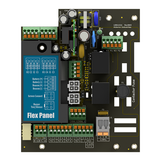
Page 2: Input Wiring
4. INCOMING VOLTAGE MUST MATCH THE CONTROL PANEL VOLTAGE. REFER TO THE PANEL SCHE- MATIC FOR COMPLETE INFORMATION. Input Wiring General Wiring The Flex Control Panel inputs are located on the bottom side of the circuit board shown below. The inputs are numbered FLT 1 - 5 as labeled on the circuit board. - Page 3 Input Voltage Levels All of the signal inputs of the Flex Control Panel are low voltage, low power circuits and are electrically isolated from the incoming line power. This isolation MUST be maintained. Therefore, the Neutral of the incoming power must NOT be connected to the secondary (low voltage) side of the circuit board.
- Page 4 Wiring Inputs With Common Float Connections If the application requires it, every input EXCEPT input 5 can be wired with a common ground connection. The figure below shows how the input grounds are connected internally. The ground connection for each input is the right side terminal (terminal 2 for FLT 1, for example).
-
Page 5: Menu System
Menu System Interface The user interface of the Flex Control Panel comprises a 16x2 OLED display, three RGB indicator LEDs, and a rotary knob (scroll wheel) used to navigate the menu system. While the system is idle, the menu screen will be turned off to conserve the life of the display. -
Page 6: Menu Conventions
Menu Conventions There are a set of arrow indicators that will appear on the bottom line of the display to aid with menu navigation. Below is a table summarizing these indicators: Indicator Image Meaning Right Arrow on The user can navigate forward or select a config from Bottom Right here. - Page 7 To Clear an Alarm To clear an alarm, simply scroll to it in the main screen (or press the test/silence switch until you see the system status screen) and then press the rotary knob. A confirmation screen will appear and ask if the alarm should be cleared.
- Page 8 Step 2 (In Setup Wizard) Set Dosing Configuration. This configures the system for Demand Dosing or Time Dosing. Note: this is the only way to change this setting. In Demand Dose Mode, if the start float triggers the pump will run continuously until the stop float goes down. In Time Dose Mode, when the timer enable float triggers the system will time dose until the timer enable float goes down.
- Page 9 Step 4 (In Setup Wizard) Configure the Float Inputs. This will configure the float inputs of the system. If the transducer was enabled, the system will ask whether or not a 2-float backup should be activated. This will set a Low Alarm/Redundant Off Float and a High Alarm/Redundant Start Float as backups in case the transducer fails. Otherwise, if the transducer was disabled, it will ask the user to enable or disable the Low Alarm Float and whether or not the Lag float should also activate a high water alarm.
-
Page 10: Optional Configurations
Optional Configurations These configurations are not absolutely critical for each application, but can be useful for customizing the behavior of the panel. Step 6 (Optional) Set Pump Exercise Timer for each pump. If set, the exercise timer will run the pump for a set amount of time after it has been idle for the configured number of days. -
Page 11: Available Settings
Step 8 (Optional) Review the Settings section of this manual for any other configurations that may be relevant to the application. The system at this point is configured for a basic application. However, there are several other configurations available in the system that may be useful depending on the specific system requirements. Stats The Flex Control Panel panel tracks several statistics for the system. - Page 12 Name Menu Path Range Description MENU->SETTINGS- Pump Run LED High, Med, This controls how bright the pump run >PASSWORD->SYSTEM Brightness Low, Off indicator LEDs are. SET UP->PUMP RUN LED System MENU->SETTINGS- High, Med, This controls how bright the system normal Normal LED >PASSWORD->SYSTEM Low, Off...
- Page 13 SET UP->PUMP LEAD Lead, Pump 2 Name Menu Path Range Description MODE Lead Pump One Configurations Name Menu Path Range Description MENU->SETTINGS- This enables or disables pump one. If >PASSWORD->PUMP Disabled, disabled, the HOA inputs will be Pump One Enable SET UP->PUMP 1->P1 Enabled unresponsive and the pump will never...
- Page 14 Name Menu Path Range Description MENU->SETTINGS- This is how long in minutes and seconds Pump One >PASSWORD->PUMP 0:00 - 5:00 pump one will run during an exercise Exercise Time SET UP->PUMP 1->P1 event. EXERCISER TIME MENU->SETTINGS- This is how long the system will run the Pump One >PASSWORD->PUMP 00:00:00 -...
- Page 15 Name Menu Path Range Description Configuration SET UP->PUMP 2->P2 Normally AUX CUT OUT Closed MENU->SETTINGS- This enables or disables the current Pump Two >PASSWORD->PUMP Disabled, sensor for pump two. Note that this is Current Sensor SET UP->PUMP 2->P2 Enabled option is only available on systems Enable CURRENT SENSE shipped with a current sensor.
-
Page 16: Input Configurations
Name Menu Path Range Description SET UP->PUMP 2->P2 DOSE ON TIME MENU->SETTINGS- Pump Two Dose >PASSWORD->PUMP This is the duration of the dose off 0 - 24:00:00 Off Time SET UP->PUMP 2->P2 portion of the dosing cycle. DOSE OFF TIME MENU->SETTINGS- This is the duration of the dose on Pump Two Peak... -
Page 17: Input Functions
Name Menu Path Range Description is the most sensitive, and 10K is the least sensitive This is the sensitivity of water sensor (seal fail MENU->SETTINGS- Water sensor) two. It represents the approximate >PASSWORD->INPUT Sensor Two 10K - 100K resistance at which the input will activate. 100K SET UP->WATER Sensitivity is the most sensitive, and 10K is the least... - Page 18 Option Name Description Number High Alarm This is a high water alarm float. Will start a high water alarm on activation. Aux Alarm This is a general use alarm input. Will start the Aux Alarm event on activation. This sets the input to function as a transducer. Note that this is only available Transducer on input 5.
- Page 19 Name Menu Path Range Description This setting controls the response of the MENU->SETTINGS- transducer input to higher and lower "LO/HI: 4/20 Transducer >PASSWORD->INPUT SET readings. Use this if the system is using mA", "LO/HI: Response Type UP->TRANSDUCER an ultra-sonic transducer with a reversed 20/4 mA"...
- Page 20 Depth UP->TRANSDUCER meters) Name Menu Path Range Description CONFIG->STOP LEVEL DEPTH MENU->SETTINGS- Transducer >PASSWORD->INPUT SET 0 - 99' 11" This is the lead level trip point of the Lead/Start UP->TRANSDUCER (30.45 transducer. Set to zero to disable. Level Depth CONFIG->LEAD LEVEL meters) DEPTH MENU->SETTINGS-...
-
Page 21: Troubleshooting
See input configurations for details on where in the menu this setting is located. © 2023 Alderon Industries. All rights reserved. | Powered by Wiki.js...
Need help?
Do you have a question about the FLEX FLXC1D and is the answer not in the manual?
Questions and answers