Table of Contents
Advertisement
Quick Links
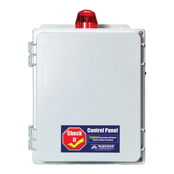
Check It
1 Phase Duplex
Operation, Maintenance and Installation Manual
Introduction
Before proceeding with the installation or operation of the control panel read all instructions thoroughly,
as well as comply with all Federal, State and Local Codes, Regulations and Practices. The control panel
must be installed by qualified personnel familiar with all applicable local electrical and mechanical codes.
Refer to the National Electrical Code (NFPA 70). Failure to properly install and test this product can result
in personal injury or equipment malfunction. All conduit connected to the panel must be sealed with
conduit sealant to prevent moisture or gases from entering the panel. NEMA 1 enclosures are for indoor
use only while NEMA 4X panel enclosures may be used indoor or outdoor. Refer to panel model name-
plate on inside of door for enclosure rating. Note: If options are ordered that affect the number of floats,
refer to the panel schematic for complete information.
Safety Guidelines
1. DO NOT USE WITH FLAMMABLE OR EXPLOSIVE FLUIDS SUCH AS GASOLINE, FUEL OIL, KEROSENE,
ETC. DO NOT USE IN EXPLOSIVE ATMOSPHERES. CONTROL PANEL SHOULD ONLY BE USED IN
WATER AND WASTEWATER APPLICATIONS THAT ARE NOT RATED AS A HAZARDOUS LOCATION.
2. DO NOT WORK ON THE CONTROL PANEL WITH LIVE VOLTAGE APPLIED TO THE CONTROL PANEL
WITH WET HANDS OR WHEN STANDING ON A WET SURFACE.
3. DISCONNECT ALL ELECTRICAL SERVICE BEFORE WORKING ON OR HANDLING THE CONTROL
PANEL
4. INCOMING VOLTAGE MUST MATCH THE CONTROL PANEL VOLTAGE. REFER TO THE PANEL SCHE-
MATIC FOR COMPLETE INFORMATION.
Description of Operation
3 Float:
With both "HOA" switches in "Auto" and the pump selector switch in "ALT": On water rise, the "off" float will
close and when the level closes the "lead" float, pump 1 will start and pump down to the "off" float. The
panel will alternate so on the next cycle pump 2 will activate. If the level reaches the "lag" float, both
pumps and the alarm will activate and pump down to the "off" float. Alarm turns off at the "off" level. For a
pump up application the floats are reversed (see float configurations Fig. #A on page 4).
4 Float:
With both "HOA" switches in "Auto" and the pump selector switch in "ALT": On water rise, the "off" float will
close and when the level closes the "lead" float, pump 1 will start and pump down to the "off" float. The
panel will alternate so on the next cycle pump 2 will activate. If the level reaches the "lag" float, both
pumps will activate and pump down to the "off" float. If the reaches the "alarm" float the alarm will
activate. Alarm turns off when the alarm float is "off". For a pump up application the floats are reversed
(see float configurations Fig. #B on page 4).
Alarm Systems
Control Panels
PO Box 827 Hawley, MN 56549 (218) 483-3034 Fax (218) 483-3036 www.alderonind.com
Panel
™
Float Switches
Leak Detection Systems
P/N: 100836
Page 1 of 4
Advertisement
Table of Contents

Related Manuals for Alderon Industries Check It Series


Summary of Contents for Alderon Industries Check It Series
- Page 1 Check It Panel ™ 1 Phase Duplex Operation, Maintenance and Installation Manual Introduction Before proceeding with the installation or operation of the control panel read all instructions thoroughly, as well as comply with all Federal, State and Local Codes, Regulations and Practices. The control panel must be installed by qualified personnel familiar with all applicable local electrical and mechanical codes.
- Page 2 Check It Panel ™ 1 Phase Duplex Operation, Maintenance and Installation Manual Circuit Board Command Center: The control panel is equipped with a circuit board and control command center. There are two “HOA” switches, a pump selector switch and a Check It switch.
- Page 3 Circuit Board Terminal Blocks: The Check It series control panel uses two terminal blocks. A 10 position main terminal block is for power and level switch connections. A separate 3 position terminal block are for dry auxiliary contacts. A 5 amp, 120 VAC max load can be applied to the auxiliary terminals.
- Page 4 4 float configuration Incoming Power Configurations: The Check It series control panels may be ordered with or without circuit breakers. In either case the incoming power for each pump is separated at the incoming power terminal block. For panels without circuit breakers individual branch circuit breakers must be wired into the control panel.
Need help?
Do you have a question about the Check It Series and is the answer not in the manual?
Questions and answers