Advertisement
Quick Links
Power Post
™
Pump Connection Center | Timed or Demand Dose, Integrated Alarm
15 Amp, 120/240VAC | PPCP Series
Alderon Industries™ | Patent Pending
QUICK START GUIDE
Step 2: Remove / Install Bottom Cover
Remove the bottom enclosure cover screw, slide directly downward until
the sound chamber is cleared (2A) and pull directly away (2B). To install,
line up the bottom enclosure cover with the grooves (2B), then slide directly
upward (2A) until it meets the top of the enclosure so the screw hole is
lined up and replace the screw at the bottom of the enclosure.
2A
Step 3: Remove / Install Post Cap
Remove Post Cap:
1) Remove Screws and Lift Cap Upwards
Install Post Cap:
1) Position text FRONT (with arrows) Forward
3) Align Fastener Holes
4) Fasten Screws to Secure Cap to Post
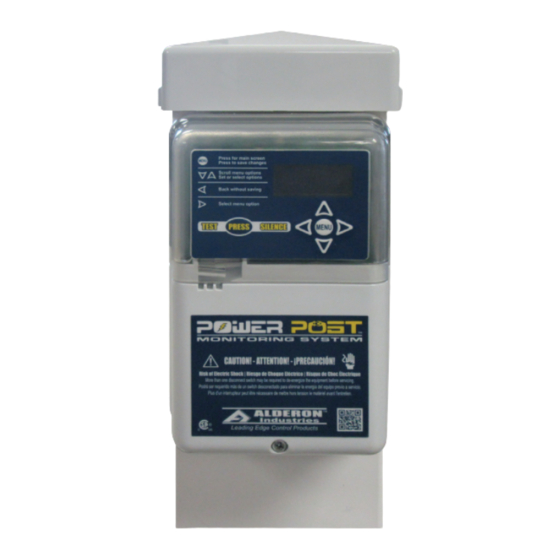
Control Panel
(Models: PPRS-0001 and PPRS-0002)
2B
Safety Guidelines
Before proceeding with the installation or operation of this product,
read all instructions thoroughly, as well as complying with all federal,
state and local codes, regulations, and practices. This product must
be installed by qualified personnel familiar with all applicable local
electrical and mechanical codes. Refer to the National Electrical Code
(NFPA 70). Failure to properly install and test this product can result in
personal injury or equipment malfunction.
Step 1: Install Post
Determine location for the post in the
ground near a tank and drill access
holes for the float switch cables using
the customer supplied conduit/fittings or
Alderon's riser connection kit. Route the
cables through access holes and wire as
described in step 5. Run the direct burial
power wires underneath the bottom of
the post as shown in the diagram.
Note: Seal all conduits to prevent moisture and gases
from entering the post per local codes.
Direct
Burial
Wires
Step 4: Installing Wire into WAGO
Before making wire connections and terminations, carefully read this
step for proper functions of both types of WAGO connectors.
WARNING: Improper use of the connectors will cause damage, DO
NOT use mechanical tools to open or close, hand usage only.
Wire Termination - Splice Connector WAGO (Fig. 1):
1) Lift tab(s) upward.
2) Insert wire(s) into slot.
3) Press tab(s) downward.
4) Make sure wire(s) are secured.
Wire Connection - Quick Snap Terminal WAGO (Fig. 2):
1) Press tab(s) outward. DO NOT open past 40° angle
2) Insert wire(s) into slot.
3) Press tab(s) inward.
4) Make sure wire(s) are secured.
(Fig. 1)
TO OPEN
WAGO
TO CLOSE
WAGO
WARNING
(Fig. 2)
TO OPEN
WAGO
TO CLOSE
WAGO
Advertisement

Related Manuals for Alderon Industries Power Post PPCP Series


Summary of Contents for Alderon Industries Power Post PPCP Series
- Page 1 Pump Connection Center | Timed or Demand Dose, Integrated Alarm 15 Amp, 120/240VAC | PPCP Series (Models: PPRS-0001 and PPRS-0002) Alderon Industries™ | Patent Pending Before proceeding with the installation or operation of this product, read all instructions thoroughly, as well as complying with all federal, state and local codes, regulations, and practices.
- Page 2 Step 5: Wiring and Piggyback Plug Connections The wiring diagram shows 10 terminals on the quick snap terminal blocks Power Wiring (steps 1 and 2) that consists of five pairs of connections. Make sure to read and review Alarm/Control the connector examples on page 7 for proper installation prior to wiring. N/L2 Power Note: The quick snap terminal blocks, are herein referred to as “terminal”...
- Page 3 2.0 | Main Menu - Resettable History 3.0 | Main Menu - Settings Part I From the RESETBLE HISTORY screen, Right arrow key from SETTINGS screen for menu, down arrow key to scroll. press right arrow key to access the menu for event statistics and then press down arrow Password (factory set to 1919) key for the available events within this menu.
- Page 4 Caution: changes / modifications not approved by Alderon Industries could void the user’s authority to operate the equipment.
Need help?
Do you have a question about the Power Post PPCP Series and is the answer not in the manual?
Questions and answers