Table of Contents
Advertisement
Quick Links
Advertisement
Table of Contents

Related Manuals for Bucktool DP25016A2


Summary of Contents for Bucktool DP25016A2
- Page 1 GET IT DONE ! 10 Drill Press " Contact Us: email: service@bucktool.com https://www.bucktool.com 909-255-1088 (8AM-5PM PST) IMPORTANT: INSTRUCTION For your own safety, read and follow all of the Safety Guidelines and Operating Instructions before operating MANUAL this product.
- Page 2 Through a combination of years of hard work and experience we’ve been able to bring you the BUCKTOOL brand you see today. We live for challenges and strive to make our customers 100% satisfied. What BUCKTOOL does for customers is special, and we want to share this with you.
-
Page 3: Table Of Contents
DP25016A2 TABLE OF CONTENTS Specifications Specifications Safety guidelines Package contents Key parts diagram Operating instructions Maintenance Exploded view Parts list Troubleshooting Warranty SPECIFICATIONS Input 120VAC, 60Hz Chuck 1/2" Motor 6.0A Speed 5(650~3100)RPM Swing 10" 2" Spindle Travel Table size 7-5/8" x 6-1/2"... -
Page 4: Safety Guidelines
DP25016A2 GENERAL SAFETY RULES WARNING Read and understand all instructions. Failure to follow all instructions listed below, may result in electric shock, fire and/or serious personal injury. READ ALL INSTRUCTIONS KNOW YOUR POWER TOOL. Read the operator’s manual carefully. Learn the applications and limitations as well as the specific potential hazards related to this tool. - Page 5 DP25016A2 that can get caught and draw you into moving parts. Rubber gloves and nonskid footwear are recommended when working outdoors. Also wear protective hair covering to contain long hair. ALWAYS WEAR EYE PROTECTION WITH SIDE SHIELDS WHICH IS MARKED TO COMPLY WITH ANSI Z87.1 WHEN USING THIS PRODUCT.
- Page 6 DP25016A2 extension cords with approved ground connection that are intended for use outdoors and so marked. STAY ALERT AND EXERCISE CONTROL. Watch what you are doing and use common sense. Do not operate tool when you are tired. Do not rush.
- Page 7 DP25016A2 ALWAYS CLAMP WORKPIECE OR BRACE AGAINST COLUMN TO PREVENT ROTATION. Never use your hand to hold the object while drilling. USE RECOMMENDED SPEED FOR DRILL ACCESSORY AND WORKPIECE MATERIAL. BE SURE DRILL BIT OR CUTTING TOOL IS SECURELY LOCKED IN THE CHUCK.
- Page 8 DP25016A2 Some examples of these chemicals are: Your risk from exposure to these chemicals varies, depending on how often you do this type of work. To reduce your exposure, work in a well-ventilated area and with approved safety equipment, such as dust masks that are specially designed to filter out microscopic particles.
- Page 9 DP25016A2 Before using an extension cord, inspect it for loose or exposed wires and cut or worn insulation. WARNING Keep the extension cord clear of the working area. Position the cord so that it will not get caught on lumber, tools or other obstructions while you are working with a power tool.
- Page 10 DP25016A2 In the event of a malfunction or breakdown, grounding provides a path of least resistance for electric current to reduce the risk of electric shock. This tool is equipped with an electric cord having an equipment-grounding conductor and a grounding plug.
-
Page 11: Package Contents
DP25016A2 Package contents No. Description Qty. Rack Table assembly Feed handles Hex wrench Hex bolt Base Rack ring Column Table adjustment handle Worm gear Table lock handle Chuck key Chuck Head assembly Fence assembly... -
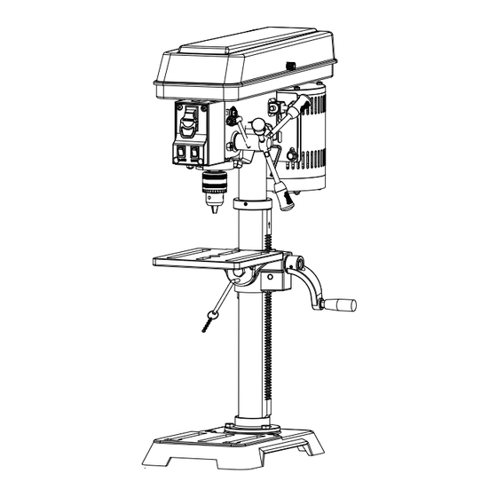
Page 12: Key Parts Diagram
DP25016A2 Key parts diagram No. Description Qty. LED Worklight Laser Table Chuck (mandrin, portabrocas) Power switch Switch key Worklight on/off switch Laser on/off switch Depth gauge Depth stop locking collar Feed handle Table adjustment handle Base Bevel scale... -
Page 13: Operating Instructions
DP25016A2 UNPACKING This product requires assembly. 1. Carefully remove the tool and any accessories from the box. Place it on a level work surface. NOTE: This tool is heavy. To avoid back injury, lift with your legs, not your back, and get help when needed. - Page 14 DP25016A2 ATTACHING COLUMN ASSEMBLY TO Column assembly BASE (FIG. 3) Place the base on a flat surface. Align screw holes Hex bolt in the column assembly with screw holes in the base. Base Place a hex bolt in each hole and tighten using an adjustable wrench.
- Page 15 DP25016A2 ASSEMBLING FENCE (FIG. 8-9) 1. Assembling the fence back stop and the end Bolt stop with a bolt and a wing nut. End stop 2. Align the mounting holes of the fence over the Fence backstop table slots. 3. Place a washer on the threaded end of the knob.
- Page 16 DP25016A2 MOUNTING THE DRILL PRESS (FIG. I2) Mounting If the drillpss is to be used in a permanent bolts location secu it to a workbench or other stable surface. If the drill press is to be used as a portable tool,...
- Page 17 DP25016A2 WARNING Do not allow familiarity with tools to makeyou careless. Remember that a careless fraction of a second is sufficient to inflict serious injury. WARNING Always wear eye protection with side shields marked to comply with ANSI Z87.1. Failure to do so could result in objects being thrown into your eyes, resulting in possible serious injury.
- Page 18 DP25016A2 SELF-EJECTING CHUCK KEY (FIG. 15) Key hole The self-ejecting chuck key ensures the chuck Chuck key key is removed from the chuck before the drill press is turned on. In order to loosen or tighten the chuck using the chuck key, push the key into the key hole located on the chuck.
- Page 19 DP25016A2 2. Align the laser lines (x) with the indentation on the workpiece. 3. Loosen the knobs and slide the fence back Wing nut Wing nut End stop stop firmly against the long side of the workpiece. Tighten the knobs when in Knob position.
- Page 20 DP25016A2 3. When drilling metal, lubricate the bit with oil to improve drilling action and increase bit life. 4. As you increase the drill size, you may need to reduce the spindle speed. 5. If drilling a through hole, make sure that the bit will not drill into the table after moving through the workpiece.
- Page 21 DP25016A2 CHANGING SPEEDS (FIG. 23) Motor The spindle speed is determined by the pulley location of the belt on the pulleys inside the head assembly. The speed chart located on the cover inside the head assembly shows the recommended speed and pulley configuration for each drilling operation.
-
Page 22: Maintenance
DP25016A2 WARNING When servicing, use only identical replacement parts. Use of any other parts may create a hazard or cause product damage. WARNING Always wear eye protection with side shields marked to comply with ANSI Z87.1. Failure to do so could result in objects being thrown into your eyes, resulting in possible serious injury. -
Page 23: Exploded View
DP25016A2... -
Page 24: Parts List
DP25016A2 Package contents Description SIZE Qty. Driving pulley set screw Driven pulley black Transmission shaf t Ball bearing Spacer ring Spring washer M6*12 Laser cover M6*10 Inner hexangular set screw Laser lamp Lamp bracket black Hex nut black Hex flat screw... - Page 25 DP25016A2 Description SIZE Qty. Head Rubber Knob Chuck Key Holder Feed shaft V belt Rivet Switch box Switch box cover Lock Switch Switch PC board Quill set screw M8 X14 Grounding Sticker Philips Screw External tooth lock wansher Cord c lamp...
- Page 26 DP25016A2 Description SIZE Qty. Chuck key RACK RING ZL Hex wrench Hex w rench Table lock handle Table bracket Inner gear Worm gear Crank handle Inner tooth shaft Work table Hex Bolt Dowel pin Motor Angle scale Rack Column table...
-
Page 27: Troubleshooting
DP25016A2 TROUBLESHOOTING GUIDE GENERAL SYMPTOM PROBABLE CAUSE CORRECTIVE ACTION Adjust belt tension. Incorrect belt tension. Noisy operation Dry spindle. Lubricate spindle. Loose spindle pulley Tighten set screws in pulleys. or motor pulley. Change speed. See “Changing Incorrect speed. Speeds” in the Adjustments section. -
Page 28: Warranty
DP25016A2 TWO-YEAR LIMITED WARRANTY Having Problems ? Give us a chance to help you before returning this product Email : service@bucktool.com https://www.bucktool.com 909-255-1088 (8AM-5PM PST) https://www.bucktool.com...
Need help?
Do you have a question about the DP25016A2 and is the answer not in the manual?
Questions and answers