Table of Contents
Advertisement
Quick Links
OPERATION & SERVICE MANUAL
Model: 09-6201-001X
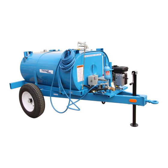
Deicing Unit
11/2022 – Rev. 06
For Spare Parts, Operations & Service Manuals or Service Needs
Scan the QR code or visit Tronair.com/aftermarket
Tronair, Inc.
Phone: (419) 866-6301 | 800-426-6301
1 Air Cargo Pkwy East
Web: www.tronair.com
Swanton, OH 43558
Email: sales@tronair.com
Advertisement
Chapters
Table of Contents
Troubleshooting

Subscribe to Our Youtube Channel
Related Manuals for Tronair 09-6201-001 Series


Summary of Contents for Tronair 09-6201-001 Series
- Page 1 OPERATION & SERVICE MANUAL Model: 09-6201-001X Deicing Unit 11/2022 – Rev. 06 For Spare Parts, Operations & Service Manuals or Service Needs Scan the QR code or visit Tronair.com/aftermarket Tronair, Inc. Phone: (419) 866-6301 | 800-426-6301 1 Air Cargo Pkwy East Web: www.tronair.com Swanton, OH 43558 Email: sales@tronair.com...
- Page 2 REVISION DATE TEXT AFFECTED 11/2009 Modified 2.4 Table and 3.0 Operation Wiring Hookups 12/2009 Deleted To Recharge Waterlogged Surge Tank Modified Surge Tank part number in Parts Lists 07/2010 Revised engine 12/2010 Added Declaration of Conformity 11/2022 Major revision...
-
Page 3: Table Of Contents
Model: 09-6201-001X Deicing Unit TABLE OF CONTENTS PAGE PRODUCT INFORMATION .............................. 1 DESCRIPTION..............................1 MODEL & SERIAL NUMBER ..........................1 MANUFACTURER .............................. 1 SAFETY INFORMATION ..............................1 USAGE AND SAFETY INFORMATION ......................1 TRAINING ..................................1 TRAINING REQUIREMENTS ..........................1 TRAINING PROGRAM ............................ -
Page 4: Product Information
Model: 09-6201-001X Deicing Unit This product can not be modified without the written approval of Tronair, Inc. Any modifications done without written approval voids all warranties and releases Tronair, Inc., its suppliers, distributors, employees, or financial institutions from any liability from consequences that may occur. -
Page 5: Assembly Instructions
The thermostat is not to be used as an “Off” device; the use of a disconnect switch or circuit breaker is recommended. The immersion heater cord end plug(s) are not supplied by Tronair due to the many different styles used. Please obtain locally. -
Page 6: Wiring Diagrams
Model: 09-6201-001X Deicing Unit WIRING DIAGRAMS (3) Element 1 PH Parallel Figure 1 – Wiring Hookup for Model: 09-6201-0011 (3) Element 3 PH Delta Parallel 21 Amps @ 480 VAC 30 Amps #120-277 VAC Figure 2 – Wiring Hookup for Models: 09-6201-0010 & 09-6201-0014 & 09-6201-0016 30 Amps #120-277 VAC (3) Element 3 PH Delta Parallel... -
Page 7: Operation
Model: 09-6201-001X Deicing Unit OPERATION SAFETY WARNINGS WARNING! High pressure hot sprays can cause serious bodily injury. BE SURE to read operating instructions including those for both engine and pump operation prior to starting the unit. ALWAYS grasp gun firmly before starting to spray. During deicing operation, hold gun firmly and exercise care and caution in handling spray gun. -
Page 8: Immersion Heater System
Model: 09-6201-001X Deicing Unit MAINTENANCE ENGINE SYSTEM Refer to Appendix I for Maintenance Information. FLUID SYSTEM Refer to Appendix III for Pump Maintenance Information. IMMERSION HEATER SYSTEM Be sure power is disconnected before doing any maintenance work. Check line connection to make sure they are tight, free of oxide build-up, and that no dust or dirt build-up is present. -
Page 9: Provision Of Spares
If warranty coverage is approved, either replacement parts will be sent or the product will have to be returned to Tronair for repairs. If the product is to be returned, a Return Material Authorization (RMA) number will be issued for reference purposes on any shipping documents. - Page 10 Model: 09-6201-001X Deicing Unit Parts List When ordering replacement parts/kits, please specify model, serial number and color of your unit. 11/2022 | Rev. 06 Page | 7...
- Page 11 Model: 09-6201-001X Deicing Unit Parts List When ordering replacement parts/kits, please specify model, serial number and color of your unit. Item Part Number Description SEE HEATER TABLE IMMERSION HEATER G-1009-08 U-BOLT G-1100-107512 BOLT, 3/8-24 X 1-1/4" HEX HD, GR 5 G-1100-109544 BOLT, 1/2-20 X 4-1/2"...
- Page 12 Model: 09-6201-001X Deicing Unit Parts List When ordering replacement parts/kits, please specify model, serial number and color of your unit. 11/2022 | Rev. 06 Page | 9...
- Page 13 Model: 09-6201-001X Deicing Unit Parts List When ordering replacement parts/kits, please specify model, serial number and color of your unit. Item Part Number Description G-1100-107514 BOLT, 3/8-24 X 1-1/2" HEX HD GR 5 G-1203-1075 JAMNUT, 3/8-24 ELASTIC G-1250-1070N FLATWASHER, 3/8 NARROW H-1031-01 PIPE, NIPPLE H-1110...
- Page 14 Model: 09-6201-001X Deicing Unit Plumbing Assembly Parts List Item Part Number Description K-1779 KIT, PUMP SEAL REPLACEMENT; consists of: Seal Ring O-ring Fabric Cup Screw Washer K-5586 KIT, PUMP DIAPHRAGM REPLACEMENT; consists of: PISTON DIAPHRAGM VALVE SEAL K-5587 KIT, PUMP VALVE REPLACMENT; consists of: VALVE ASSY VALVE SEAL 11/2022 | Rev.
- Page 15 APPENDIX I Hypro Gasoline Engines Manual...
- Page 17 PowerPro Gasoline Engines Form L-1512 5/12, Rev. B Operation, Repair, and Parts Manual PowerPro Model Number 200 and 390 HY200 (6.5 hp) - 2541-0045 (3/4” keyed shaft) 2541-0046 (5/8” threaded shaft) HY390 (13.0 hp) - 2541-0048 (1” keyed shaft) 2541-0049 (1” keyed shaft w/electric start) 2541-0050 (1”...
- Page 18 Table of Contents ENGINE SAFETY ............................. 3 COMPONENTS & CONTROL LOCATIONS .................... 4 CONTROLS .............................. 5 CHECK BEFORE OPERATION ....................... 6 OPERATION ............................7 MAINTENANCE ............................9 STORAGE/TRANSPORTATION ......................16 TROUBLESHOOTING ........................... 18 TECHNICAL & CONSUMER INFORMATION ..................19 SPECIFICATIONS ..........................22 ENGINE REPLACEMENT PARTS ......................
-
Page 19: Engine Safety
Engine Safety Information California Proposition 65 Warning -- This Hot Exhaust product and related accessories contain chemicals • The muffler becomes very hot during operation known to the State of California to cause cancer, and remains hot for a while after stopping the en- birth defects or other reproductive harm. -
Page 20: Components & Control Locations
Components & Control Locations Throttle Lever Muffler Ignition Switch Starter Grip Spark Plug Recoil Starter Canister Choke Lever Air Cleaner Fuel Valve Lever Fuel Filler Cap Fuel Tank Oil Drain Plug Oil Filler Cap/Dipstick... -
Page 21: Controls
Controls Fuel Valve Lever Choke Lever The fuel valve opens and closes the passage The choke lever opens and closes the choke valve between the fuel tank and the carburetor. The in the carburetor. The CLOSE position enriches the fuel valve lever must be in the ON position for the fuel mixture for starting a cold engine. -
Page 22: Check Before Operation
Check Before Operation IS YOUR ENGINE READY TO GO? Check the Engine For your safety, and to maximize the service life of • Check the engine oil level. Running the engine your equipment, it is very important to take a few with a low oil level can cause engine damage. -
Page 23: Operation
Operation 3. Move the throttle lever away from the SLOW SAFE OPERATING PRECAUTIONS position, about 1/3 of the way toward the FAST Before operating the engine for the first time, position. please review the IMPORTANT SAFETY Some engine applications use a remotely-mount- INFORMATION and the section titled BEFORE ed throttle control rather than the engine-mounted OPERATION. - Page 24 Operation SETTING ENGINE SPEED STOPPING THE ENGINE Position the throttle lever for the desired engine To stop the engine in an emergency, simply turn speed. Some engine applications use a remote- the engine switch to the OFF position. Under nor- ly-mounted throttle control rather than the mal conditions, use the following procedure.
-
Page 25: Maintenance
Maintenance THE IMPORTANCE OF MAINTENANCE MAINTENANCE SAFETY Good maintenance is essential for safe, econom- Some of the most important safety precautions are ical, and trouble-free operation. It will also help as follows. (Note: We cannot warn you of every reduce air pollution. conceivable hazard that can arise in performing maintenance. - Page 26 Maintenance MAINTENANCE SCHEDULE REGULAR SERVICE PERIOD First Every Every Every Performed at every indicated month or Each month 3 months 6 months year operating hour interval, whichever comes first. Item 20 hours 50 hours 100 hours 300 hours • Engine oil Check level °...
- Page 27 Maintenance Spilled fuel is not only a fire hazard, it causes envi- 3. If the oil level is low, fill to the edge of the oil filler ronmental damage. Wipe up spills immediately. hole with the recommended oil. 4. Screw in the filler cap/dipstick securely. Fuel can damage paint and plastic.
- Page 28 Maintenance However, to avoid the inconvenience of an unex- AIR FILTER INSPECTION pected shutdown, fill to the upper limit, and check Remove the air cleaner cover and inspect the fil- the oil level regularly. ter. Clean or replace dirty filter elements. Always 4.
- Page 29 Maintenance Dual-Filter Element Types Oil-Bath Type 1. Remove the wing 1. Remove the wing nut, and remove the air clean- nut from the air cleaner er cap and cover. cover, and remove the air 2. Remove the air filter from the cover, wash the cleaner cover.
- Page 30 Maintenance 3. Inspect the spark plug. Replace it if the elec- SEDIMENT CUP CLEANING trodes are worn, or if the insulator is cracked or 1. Move the fuel valve to the OFF position, and chipped. then remove the fuel sediment cup and O-ring. 4.
- Page 31 Maintenance SPARK ARRESTER SERVICE (optional equipment) Your engine is not factory-equipped with a spark arrester. In some areas, it is illegal to operate an engine without a spark arrester. Check local laws and regulations. A spark arrester is available from authorized servicing dealers.
-
Page 32: Storage/Transportation
Storage/Transportation You can extend fuel storage life by adding a fuel STORING YOUR ENGINE stabilizer that is formulated for that purpose, or you Storage Preparation can avoid fuel deterioration problems by draining Proper storage preparation is essential for keeping the fuel tank and carburetor. your engine trouble free and looking good. - Page 33 Storage/Transportation Storage Precautions Removal from Storage 1. Change the engine oil. Check your engine as described in the section CHECK BEFORE OPERATION. 2. Remove the spark plugs. If the fuel was drained during storage prepara- 3. Pour a tablespoon (5-10 cc) of clean engine oil tion, fill the tank with fresh gasoline.
-
Page 34: Troubleshooting
Troubleshooting ENGINE WILL NOT START Possible Cause Correction 1. Electric starting: Battery discharged. Recharge battery. check battery. 2. Check control positions. Fuel valve OFF. Move lever to ON. Choke OPEN. Move lever to CLOSE unless engine is warm. Engine switch OFF. Turn engine switch to ON. -
Page 35: Technical & Consumer Information
Technical & Consumer Information 2. Connect the battery negative (-) cable to an TECHNICAL INFORMATION engine mounting bolt, frame bolt, or other good Serial Number Location engine ground connection. 3. Connect the battery positive (+) cable to the battery positive (+) terminal. 4. - Page 36 Technical & Consumer Information Models: 2541-0047 thru 2541-0051 When the carburetor has been modified for high altitude operation, the air-fuel mixture will be too lean for low altitude use. Operation at altitudes below 5,000 feet (1,500 meters) with a modified carburetor may cause the engine to overheat and result in serious engine damage.
- Page 37 Technical & Consumer Information EMISSION CONTROL SYSTEM Maintenance INFORMATION Follow the maintenance schedule. Remember that Source of Emissions this schedule is based on the assumption that your machine will be used for its designed purpose. The combustion process produces carbon Sustained high-load or high-temperature operation, monoxide, oxides of nitrogen, and hydrocarbons.
-
Page 38: Specifications
Specifications... -
Page 39: Engine Replacement Parts
Engine Replacement Parts... -
Page 40: Wiring Diagrams
Wiring Diagrams... - Page 41 Wiring Diagrams Engine Type with Oil Alert and without Electric Starting...
- Page 42 Optional Parts BATTERY Use a battery rated at 12V, 18Ah or more. Do not reverse polarity. Serious damage to the engine and/or battery may occur. A battery can explode if you do not follow the correct procedure, seriously injuring anyone nearby.
-
Page 43: Emissions Warranty
Emissions Warranty... - Page 44 Limited Warranty on PowerPro Gasoline Engines Hypro warrants to the original purchaser of its PowerPro gasoline engine to be free from defects in material and workmanship under normal use for the period of one (1) year from the date of purchase. This warranty does not cover freight damage, normal wear and tear, or damage caused by misapplication, lack of routine maintenance, negligence, alterations, or repair that affects the performance or reliability of the engine (see limitations and exclusions listed below).
- Page 45 APPENDIX II Hypro Diaphragm Pump Manual...
- Page 47 DIAPHRAGM PUMPS INSTALLATION AND OPERATION MANUAL pentair.com...
- Page 48 TABLE OF CONTENTS Safety Information ....................................3 General Information ....................................5 Installation and Operations ................................... 6 Maintenance ......................................8 Low Pressure 15 Bar Performance & Specifications ..............................10 Installation ....................................11 Replacement Parts List ................................12 Medium Pressure 20-40 Bar Performance & Specifications ..............................18 Installation ....................................20 Replacement Parts List ................................
-
Page 49: Safety Information
SAFETY INFORMATION Save these instructions: This manual contains important Personal Safety: instructions that should be followed during installation, Wear safety glasses at all times when working with pumps. operation, and maintenance of the product. Keep work area clean, uncluttered and properly lighted. ... - Page 50 SAFETY INFORMATION Do not pump at pressures higher than the maximum HAZARDOUS SUBSTANCE ALERT recommended pressure. Always drain and flush pump before servicing or Operate the pump between a temperature ranges of 45° to disassembling for any reason (see instructions). ...
-
Page 51: General Information
GENERAL INFORMATION DESCRIPTION AND USES MISUSES Hypro Diaphragm pumps are intended for creating or boosting Hypro centrifugal pumps are designed to operate effectively dynamic pressure for non-food purposes with clean and within the specified speed, pressure and environmental ranges. approved fluids in a watery solution which are compatible with Going outside of these ranges will void the warranty and could the materials of the pump at temperatures between 45°... -
Page 52: Installation And Operations
INSTALLATION AND OPERATION PUMP PLUMBING SHAFT ADAPTER KIT INSTALLATION Use only pipe, fittings, accessories, hose, etc. rated for the Order the appropriate shaft kit according to the chart on Spec maximum pressure rating of the pump. Sheet. Always mount pump with oil sight tube in upright position Mount shaft adapter (Ref. - Page 53 INSTALLATION AND OPERATION OPERATION First back out the pressure regulator adjustment knob to zero. Before start up check that oil is halfway up to the clear Then rotate the Pressure Release knob to Pressure arrow oil sight tube. If necessary, fill to the correct level with direction.
-
Page 54: Maintenance
MAINTENANCE MAINTENANCE SCHEDULE REGULAR SERVICE PERIOD Every 3 Every 6 First month Performed at every indicated month or operating hour interval, First Use Each Use months or months or or 40 hours whichever comes first. 500 hours 1000 hours Check Level Crankcase Oil Replace Check Level... - Page 55 MAINTENANCE DIAPHRAGM REPLACEMENT Change diaphragms every 500 hours or three months, whichever comes first. Drain oil from crankcase as instructed previously. Remove pump head bolts and heads. Remove the bolt securing the diaphragm (See Figure 4). Remove the old diaphragm and the washer (See Figure 4). Install a new diaphragm.
- Page 56 DIAPHRAGM PUMP: LOW PRESSURE RANGE 15BAR "Max. Flow "Max. Pressure "Max. Speed "Power No. of Model Number USGPM [LPM]" PSI [BAR]" RPM" HP [KW]" Diaphragm 9915-DP803 21.7 [82] 218 [15] 3.2 [2.4] "Max. Flow "Max. Pressure "Max. Speed "Power No. of Model Number USGPM [LPM]"...
-
Page 57: Low Pressure 15 Bar
LOW PRESSURE 15 BAR PERFORMANCE AND SPECIFICATIONS CONTROL UNIT KIT INSTALLATION For all discharge hoses, use hose with an operating pressure The control units are designed for control of pressure and flow rating equal to or greater than the maximum pressure rating of rate. - Page 58 LOW PRESSURE 15 BAR REPLACEMENT PARTS FIGURE 7: MODEL DP803 L-1600 (04/01/21)
- Page 59 LOW PRESSURE 15 BAR REPLACEMENT PARTS TORQUE CHART DP803 9915-KIT2004 REF. No. Qty. ft.Lbs KIT DIAPHRAGM DP803 DP1003 REF. No. DESCRIPTION QTY. 18.5 PRE-SET DURAMAX PISTON 14.8 DIAPHRAGM "5 "3.7 O-RING 3.53X28.17 (LOXEAL 55-14)" (LOXEAL 55-14)" 32.5 9915-KIT2104 KIT SERVICE VALVE DP803 DP1003 32.5 REF.
- Page 60 LOW PRESSURE 15 BAR REPLACEMENT PARTS FIGURE 8: MODEL DP1003 L-1600 (04/01/21)
- Page 61 LOW PRESSURE 15 BAR REPLACEMENT PARTS TORQUE CHART DP1003 9915-KIT2004 REF. No. Qty. ft.Lbs KIT DIAPHRAGM DP803 DP1003 REF. No. DESCRIPTION QTY. 18.5 PRE-SET DURAMAX PISTON DIAPHRAGM (LOXEAL 55-14) (LOXEAL 55-14) O-RING 3.53X28.17 32.5 9915-KIT2104 32.5 KIT SERVICE VALVE DP803 DP1003 29.5 REF.
- Page 62 LOW PRESSURE 15 BAR REPLACEMENT PARTS FIGURE 9: MODEL DP2505 L-1600 (04/01/21)
- Page 63 LOW PRESSURE 15 BAR REPLACEMENT PARTS TORQUE CHART DP2505 9915-KIT2005 REF. No. Qty. ft.Lbs KIT DIAPHRAGM DP2505 REF. No. DESCRIPTION QTY. 18.4 PRE-SET DURAMAX PISTON 14.8 DIAPHRAGM O-RING 4.5x40 VITON (LOXEAL 24-18)" (LOXEAL 24-18)" 29.5 9915-KIT2105 16.3 KIT SERVICE VALVE DP2505 16.3 REF.
- Page 64 DIAPHRAGM PUMP: MEDIUM PRESSURE RANGE 20 - 40BAR "Max. Flow "Max. Pressure "Max. Speed "Power No. of Model Number USGPM [LPM]" PSI [BAR]" RPM" HP [KW]" Diaphragm 9915-DP252 9915-DP252GRGI 6.3 [24] 290 [20] 3450 1.4 [1.1] 3450 9915-DP252GRGI58 "Max. Flow "Max.
- Page 65 MEDIUM PRESSURE 20-40 BAR PERFORMANCE AND SPECIFICATIONS DRIVE OPTIONS Order the appropriate shaft adapter kit or gear reduction unit Control Units: Control units are available for easy flow and for the drive option requirements. Refer to the adjoining chart pressure control of your sprayer system. These units include for proper selection.
-
Page 66: Installation
MEDIUM PRESSURE 20-40 BAR INSTALLATION INSTALLATION INSTRUCTIONS FOR GEAR REDUCTION KIT The 9915-KIT1105 gear reducer is designed for direct mounting 9915-KIT1103 (REFER TO FIGURE 10) the diaphragm pumps (listed in chart on page 19) onto an 8 hp gasoline engine with a flange mounting and 1” solid shaft. NOTE: Hypro recommends a blue thread locking compound on all threaded fasteners that do not require lock washers. -
Page 67: Installation
MEDIUM PRESSURE 20-40 BAR INSTALLATION FIGURE 10: MODEL 9915-KIT1103 FIGURE 11: MODEL 9915-KIT1105 L-1600 (04/01/21) - Page 68 MEDIUM PRESSURE 20-40 BAR INSTALLATION CONTROL UNIT KIT INSTALLATION The control units are designed for control of pressure and flow For all discharge hoses, use hose with an operating pressure rate. Use appropriate model (as specified in chart on page 19) rating equal to or greater than the maximum pressure rating of to mount on particular pump model and pressure/flow ranges.
- Page 69 MEDIUM PRESSURE 20-40 BAR INSTALLATION PRESSURE REGULATOR ADJUSMENT KNOB OUTLET PRESSURE REGULATOR ADJUSMENT KNOB FIGURE 12: MODEL 9915-KIT1001 OUTLET PRESSURE REGULATOR ADJUSMENT OUTLET KNOB FIGURE 13: MODEL 9915-KIT1002 & 9915-KIT1008 PRESSURE REGULATOR OUTLET ADJUSMENT KNOB FIGURE 14: MODEL 9915-KIT1003 L-1600 (04/01/21)
- Page 70 MEDIUM PRESSURE 20-40 BAR REPLACEMENT PARTS FIGURE 15: MODELS 9915-DP252, 9915-DP302 L-1600 (04/01/21)
- Page 71 MEDIUM PRESSURE 20-40 BAR REPLACEMENT PARTS 9915-KIT2001 TORQUE CHART DP252 DP302 REF. No. Qty. ft.Lbs KIT DIAPHRAGM DURAMAX DP252 DP302 REF. No. DESCRIPTION QTY. PRE-SET DURAMAX PISTON DIAPHRAGM (STD.) DAMPENER DIAPHRAGM O-RING D.2.62X15.54 O-RING D.2.62X22.22 O-RING D.2.62X26.65 29.5 9915-KIT2101 KIT SERVICE VALVE DP252 DP302 REF.
- Page 72 MEDIUM PRESSURE 20-40 BAR REPLACEMENT PARTS FIGURE 16: MODEL 9915-D303, 9915-D403 L-1600 (04/01/21)
- Page 73 MEDIUM PRESSURE 20-40 BAR REPLACEMENT PARTS TORQUE CHART D303, D403 9915-KIT2002 REF. No. Qty. ft.Lbs KIT DIAPHRAGM D303, D403 REF. No. DESCRIPTION QTY. DURAMAX PISTON DIAPHRAGM VALVE SEAL 16.2 16.2 16.2 9915-KIT2102 Tolerance on Torque value: +0/-10% KIT SERVICE VALVE D303, D403 REF.
- Page 74 MEDIUM PRESSURE 20-40 BAR REPLACEMENT PARTS FIGURE 17: MODEL 9915-D503 L-1600 (04/01/21)
- Page 75 MEDIUM PRESSURE 20-40 BAR REPLACEMENT PARTS TORQUE CHART D503 9915-KIT2008 KIT DIAPHRAGM D503 REF. No. Qty. ft.Lbs REF. No. DESCRIPTION QTY. 16.2 DURAMAX PISTON DIAPHRAGM O-RING 2.62X18.72 32.5 32.5 9915-KIT2108 32.5 KIT SERVICE VALVE D503 Tolerance on Torque value: +0/-10% REF.
- Page 76 MEDIUM PRESSURE 20-40 BAR REPLACEMENT PARTS FIGURE 18: MODEL 9915-DP503 L-1600 (04/01/21)
- Page 77 MEDIUM PRESSURE 20-40 BAR REPLACEMENT PARTS TORQUE CHART DP503 9915-KIT2003 KIT DIAPHRAGM DP503 REF. No. Qty. ft.Lbs REF. No. DESCRIPTION QTY. PRE-SET DURAMAX PISTON DIAPHRAGM 32.4 O-RING 2.62X18.72 16.2 O-RING 2.62X20.24 32.4 16.2 9915-KIT2103 KIT SERVICE VALVE DP503 REF. No. DESCRIPTION QTY.
- Page 78 DIAPHRAGM PUMP: HIGH PRESSURE RANGE 50 BAR "Max. Flow "Max. Pressure "Max. Speed "Power No. of Model Number USGPM [LPM]" PSI [BAR]" RPM" HP [KW]" Diaphragm 9915-D1063 27.9 [106] 725 [50] 13.9 [10.4] "Max. Flow "Max. Pressure "Max. Speed "Power No.
- Page 79 HIGH PRESSURE 50 BAR INSTALLATION CONTROL UNIT KIT INSTALLATION The control units are designed for control of pressure and flow Always wear safety goggles when working with spring-loaded fasteners or devices. rate. Use appropriate model (as specified in chart on page 32) to use with particular pump model and pressure/flow ranges.
- Page 80 HIGH PRESSURE 50 BAR REPLACEMENT PARTS FIGURE 20: MODEL 9915-D1063 L-1600 (04/01/21)
- Page 81 HIGH PRESSURE 50 BAR REPLACEMENT PARTS TORQUE CHART D1063 9915-KIT2006 REF. No. Qty. ft.Lbs KIT DIAPHRAGM D1063 32.5 REF. No. DESCRIPTION QTY. 16.2 DESMOPAN PISTON DIAPHRAGM NBR BALLASTER DIAPHRAGM 18.5 O-RING DIA.2,62x22,22 16.2 32.5 72.2 Tolerance on Torque value: +0/-10% 9915-KIT2106 KIT SERVICE VALVE D1063 REF.
- Page 82 HIGH PRESSURE 50 BAR REPLACEMENT PARTS FIGURE 21: MODEL 9915-D1504 L-1600 (04/01/21)
- Page 83 HIGH PRESSURE 50 BAR REPLACEMENT PARTS TORQUE CHART D1504 9915-KIT2007 REF. No. Qty. ft.Lbs KIT DIAPHRAGM D1504 16.2 REF. No. DESCRIPTION QTY. 16.2 DESMOPAN PISTON DIAPHRAGM NBR BALLASTER DIAPHRAGM 32.5 O-RING DIA.2.62x22.22 18.5 79.7 32.5 16.2 9915-KIT2107 Tolerance on Torque value: +0/-10% KIT SERVICE VALVE D1504 REF.
-
Page 84: Troubleshooting
TROUBLESHOOTING SYMPTOM POSSIBLE CAUSE CORRECTIVE ACTION Remove valve and check for debris. One or more valves are seating improperly. Remove any debris found. Examine the valve seating and clean them. The pump does not draw water Examine and clean the suction line. Suction line is plugged or collapsed. - Page 85 TROUBLESHOOTING Examples of diaphragms failures & causes CIRCULAR FRACTURE ON PISTON SIDE OF DIAPHRAGM WHICH IS SAME DIAMETER AS PISTON POSSIBLE CAUSES: BLOW-BY BETWEEN PISTON AND SLEEVE 2. SUCTION HAS TOO MUCH PRESSURE (EXCESSIVE HEAD) 3. LOW PUMP RPM 4. DELIVERY VALVE NOT SEALING 5.
-
Page 86: Warranty
WARRANTY Limited Warranty on HYPRO/SHURFLO Agricultural Pumps & Accessories Hypro/SHURflo (hereafter, “Hypro”) agricultural products are warranted to be free of defects in material and workmanship under normal use for the time periods listed below, with proof of purchase. - Pumps: one (1) year from the date of manufacture, or one (1) year of use. This limited warranty will not exceed two (2) years, in any event. - Page 87 APPENDIX III Declaration of Conformity...
- Page 89 Enter serial number(s) Declaration: Tronair has assessed the equipment described above against the Essential Health and Safety Requirements of one or more Directives. Based on this assessment, the equipment described above is deemed to comply with the directive(s) listed below.
Need help?
Do you have a question about the 09-6201-001 Series and is the answer not in the manual?
Questions and answers