Table of Contents
Advertisement
Quick Links
FemtoPUMP
Multi-output grease electric pump
User and Maintenance Manual
Translation of original instructions
Manual drafted in compliance
C2387IE WK 40/23
with directive 2006/42
DropsA products can be purchased from DropsA branches and authorised distributors.
Visit the website www.dropsa.com/contact or send an e-mail to sales@dropsa.com
Advertisement
Table of Contents

Related Manuals for DROPSA Femto 0891111


Summary of Contents for DROPSA Femto 0891111
- Page 1 Multi-output grease electric pump User and Maintenance Manual Translation of original instructions Manual drafted in compliance C2387IE WK 40/23 with directive 2006/42 DropsA products can be purchased from DropsA branches and authorised distributors. Visit the website www.dropsa.com/contact or send an e-mail to sales@dropsa.com...
-
Page 2: Table Of Contents
Table of contents INTRODUCTION .................................... 3 GENERAL DESCRIPTION ................................3 ............................3 2.1. centralised lubrication (BASIC) ........................3 2.2. DIRECT TO POINT (multi-line) LUBRICATION ..............................3 2.3. Features and benefits Safety and precautions for use ..............................4 PRODUCT IDENTIFICATION ................................5 TECHNICAL CHARACTERISTICS ..............................6 PARTS ...................................... -
Page 3: Introduction
The latest version of this manual is available from the Technical-Commercial Office or by consulting our website http://www.dropsa.com. Please read this manual carefully and keep it in a safe place so that it is always available to operators who wish to consult it. -
Page 4: Safety And Precautions For Use
3. SAFETY AND PRECAUTIONS FOR USE This manual must be read before carrying out any operation. We recommend that you comply with the safety regulations of the country in which the equipment is installed and employee specialised personnel in the various maintenance, use, installation, etc. -
Page 5: Product Identification
4. PRODUCT IDENTIFICATION A plate on the pump tank shows the product code, power supply voltages and basic characteristics. WARNING Removing the pump identification plate is prohibited NOTICE The pump includes some items made with alloyed metals that have a percentage of Lead (CAS 7439-92-1) <... -
Page 6: Technical Characteristics
5. TECHNICAL CHARACTERISTICS GENERAL TECHNICAL CHARACTERISTICS Pumping system Type spring-return cam /cycle 0.005 - 0.01 - 0.015 - 0.025 - 0.05 Multi-line /rev] [0.0003 - 0.0006 - 0.0009 - 0.0015 - 0.003] Flow rate: Basic cm /cycle 0.19 [0.011] /min] Basic Reg. - Page 7 CIRCUIT BOARD TECHNICAL SPECIFICATIONS Operating voltages 12 - 24 ±10% Reverse polarity protection on power supply Power supply noise protection (Spike) Remote signalling of cycle status and alarm Hardware specifications Cycle control via external sensor Start via external pulse Reset/Extra-cycle via external button 3 input signals Same supply voltage 2 output signals...
-
Page 8: Parts
6. PARTS The main parts that make up the pump in the various versions, the accessories and optionals are shown below. 6.1. FEMTO PUMP WITH FOLLOWER PLATE Max lev. Reed Tank 1 Kg housing (Optional) Follower plate Identification plate “Progressive” pumping Minimum level unit fitting (M22x1.5) Reed... -
Page 9: Femto Pump With Stirring Paddle 1 L
6.2. FEMTO PUMP WITH STIRRING PADDLE 1 L Max lev. Reed Tank 1 Kg housing (Optional) Stirring paddle Identification plate “Progressive” Minimum level Reed pumping unit fitting (M22x1.5) Cycle sensor connector M12 4 Pin 8 pumping unit AMP 7 Pin* power fitting (M12x1) supply connector "Multi-line"... -
Page 10: Femto Pump With Stirring Paddle 2 L
6.3. FEMTO PUMP WITH STIRRING PADDLE 2 L Tank 2 Kg Max lev. Reed housing (Optional) Stirring paddle Identification plate “Progressive” pumping unit fitting (M22x1.5) Cycle sensor connector M12 4 Pin 8 pumping unit fitting (M12x1) AMP 7 Pin* power "Multi-line"... -
Page 11: Multi-Line" Pumping Units
6.5. “MULTI-LINE” PUMPING UNITS M12x1 Notches Output G1/8" 5 notches 1 notch 2 notches 3 notches 4 notches 0.05 cm /rev 0.005 cm /rev 0.015 cm /rev 0.01 cm /rev 0.025 cm /rev [0.003 in /rev] [0.0003 in /rev] [0.0009 in /rev] [0.0006 in /rev]... -
Page 12: Unpacking And Installation
7. UNPACKING AND INSTALLATION 7.1. UNPACKING Once you have identified a suitable location for installation, open the packaging, take out the pump and make sure that it has not been damaged during transport or storage. The packaging material does not require special disposal precautions, as it is not dangerous or polluting in any way. - Page 13 Manual Version Supply Connector VDC + VDC - COM. Level contact 7.4.1. CONNECTION DIAGRAM N.O. Level contact in the absence of fluid Not conn Not conn Not conn Automatic Version Power Supply Connect VDC + VDC - Not conn. Alarm status output Cycle status output Reset Input Stand-by Pulse Input...
-
Page 14: Installing The Maximum Level Alarm, Only For Versions With Follower Plate (Optional)
Cycle Sensor Connector Description Connection CONTACT Cycle Sensor Input NOTICE Pins 1 and 3 of the cycle sensor connectors supply the same voltage as the ends of the power connector. This voltage is used to power the sensor directly. 7.5. INSTALLING THE MAXIMUM LEVEL ALARM, ONLY FOR VERSIONS WITH FOLLOWER PLATE (OPTIONAL) Screw the alarm sensor into the appropriate seats on the tank, keeping the connection wires towards the pump fastenings. -
Page 15: Operating Instructions
Use safety gloves and goggles as prescribed on the lubricant safety data sheet. • DO NOT use aggressive lubricants against NBR seals, when in doubt consult Dropsa S.p.A. technical department who will provide a detailed data sheet on recommended lubricants. - Page 16 Vent channel Max lev. Min lev. Grease Filling connection FILLED PUMP TO BE VENTED PUMP BEING FILLED VACUUM PUMP FILLED PUMP VACUUM PUMP FILLED PUMP STIRRING PADDLE V. STIRRING PADDLE V. 8.2.2. TANK FILLING (STIRRING PADDLE VERSION) Tank filling must be carried out using the dedicated device complete with filter to be interfaced to the filling connection. A manual filling KIT can also be used, interfaced on the M22 thread where the Basic pumping unit is not present.
-
Page 17: Adjustable Pumping Unit Setting
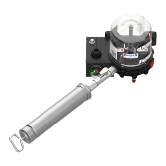
8.2.3. TANK FILLING WITH MANUAL PUMP KIT (ALL VERSIONS) Where available, mount the fittings for connecting the manual filling pump. Open the tap, engage the pump on the appropriate connection and move the pump plunger, close the tap and remove the cartridge. -
Page 18: Setup
• Check pump start-up. • Check that the machine is adequately lubricated (if there are any doubts as to its correct operation, contact the Dropsa S.p.A. technical office to request testing). 8.6 START UP No adjustments are foreseen; the pump is electrically powered by a system that controls its operation and manages the minimum level contact if the LTC card is not present. -
Page 19: Lubrication Control Settings
10. LUBRICATION CONTROL SETTINGS 10.1. DESCRIPTION OF PARTS The pump is equipped with a configuration dip-switch, two dip-switches for adjusting the lubrication time and the stand-by phase and two LEDs for operation and alarm status. CONFIG dip-switch WORK dip-switch Used to set the various Used to set the pump functions lubrication time... - Page 20 10.1.1. CONFIG. DIP-SWITCH Config. dip-switch Switch Function Switch Function Description Status status After the pump has been started up, the lubrication cycle will resume Last Status from the state prior to shut-down. Start-up from Pre- After the pump has been started up, a new lubrication cycle will start. lubrication Time Stand-by is time-based...
- Page 21 10.1.2. STAND-BY DIP-SWITCH This dip-switch is used to configure the stand-by time/pulses. To set the desired time/pulses, the combination of one or more switches and the chosen scale can be set via the Config dip-switch. The table below shows the values of each individual switch. NOTICE At least one active switch must be present for correct operation Stand-by Dip-switch...
- Page 22 10.1.3. WORK SWITCH This dip-switch is used to configure the lubrication time. To set the desired time, the combination of one or more switches and the chosen scale can be set via the Config dip-switch. The table below shows the values of each individual switch. Work Dip-switch Work Switch With scale 1 (Seconds)
-
Page 23: Cycle Led
10.1.4 CYCLE LED The green “Cycle” LED will light up in different ways depending on the current status of the pump. If the pump is in 'Stop' status, the light stays off; if it is lubricating the light will stay on and if the pump is in stand-by the light will be flashing. 10.1.5 ALARM LED The red “Alarm”... -
Page 24: Troubleshooting
Below is a diagnostic table highlighting the main faults, probable causes and possible solutions to be activated immediately (contact Dropsa). In case of doubts and/or problems that cannot be solved, do not try to disassemble parts of the pump; contact the Dropsa Technical Office. -
Page 25: Maintenance Procedures
12. MAINTENANCE PROCEDURES The pump does not require special equipment for any inspection and/or maintenance operations. In any case, it is recommended to use equipment and personal protective equipment suitable for use (gloves, protective glasses, etc.) and in good condition in accordance with the regulations in force to avoid damage to persons or parts of the pump. The unit has been designed and constructed to require minimal maintenance operations. -
Page 26: Ordering Information
14.ORDERING INFORMATION 14.1. PUMP ORDERING CODE TYPE VOLTAGE TANK MANUAL AUTOMATIC VERSION VERSION (Without (With integrated Controller) Controller) 12 VDC 0891111 0891131 0891112 0891132 0891114 0891134 0891115 0891135 0891113 0891133 Version with follower plate disc Femto 24 VDC 0891121 0891141 0891122 0891142 0891124... - Page 27 14.2.1.FACTORY-PRE-SET PUMPS The above identification string has been split into the following five sections: Ø SECTION 1: Product ID Code + Order Code. digit string which identifies the series (0891) of the FEMTO pump and the "basic" order code Ø SECTION 2: Basic Pumping Units. Up to 3 digit string that indicates whether or not the Basic pumping units, bypass and filling kit are included.
- Page 28 14.2.2. POSITION OF BASIC/MULTI-LINE PUMPING UNITS & REFILLING KIT (ALL VERSIONS) The position of the pumps elements is defined: Alphanumeric character = Pump element “Basic" & Refilling kit Numeric character Pump element "Multiline" “Basic” “Multiline” Example of ordering with pumping units: 0891111P10 Ø...
-
Page 29: Spare Part Kits And Accessories
15. SPARE PART KITS AND ACCESSORIES SPARE PARTS OPTIONAL KITS AND ACCESSORIES CODE DESCRIPTION CODE DESCRIPTION 0890011 2kg tank kit + seals kit 3133723 Cartridge-loading-kit 0890012 1kg tank kit Maximum level sensor kit, only for versions 0890014 0888185 Pumping unit replacement plug (Multi-line) with follower plate (optional) 3234300 Pumping unit replacement plug (Basic) - Page 30 2 Kg Femto Pump all versions Dimensions in: mm [in]...
-
Page 31: Handling And Transport
17. HANDLING AND TRANSPORT Before shipping, the pumps are carefully packed in a cardboard box. When transporting and storing the equipment, pay attention to the orientation indicated on the box. Upon receipt, check the packaging for damage and store the pump in a dry place. -
Page 32: Lubricants
• Use of unsuitable lubricant. à The lubricant characteristics are shown both on the pump and in this User and Maintenance Manual (if in doubt, contact the Dropsa Technical Office): FLUIDS THAT ARE NOT PERMITTED FLUIDS HAZARDS... -
Page 33: Copyright
Contraventions shall be liable for damages. Reprints, even of extracts, are only permitted with the approval of DropsA S.p.A. We reserve the right to implement technical modifications to the machine at any time in order to improve safety, reliability, function and design.
Need help?
Do you have a question about the Femto 0891111 and is the answer not in the manual?
Questions and answers