
Related Manuals for Kverneland 9542


Summary of Contents for Kverneland 9542
- Page 1 9542 / 9546 Assembly instructions Original assembly instructions Edition 03.2015 Date of print 07.2015 Language EN-EU Machine number VF658210550 – / VF65835400 – Model VF6582 / VF6583 Document number A131024100...
- Page 2 Copyright by Kverneland Group Gottmadingen N. V., Germany. Reproduction, transfer to other media, translation or the use of extracts or parts of this manual without the explicit permission of Kverneland, is not permitted. All rights reserved. The contents of this operator's manual are subject...
-
Page 3: Table Of Contents
Table of contents Table of contents Preliminary information ......Target group for these assembly instructions Symbols used Safety ............For your safety Screwed connections Overview ............ Designation of components Crate packaging Pallet packaging Crate packaging ........Requirements Main frame Fitting the rotor Fitting the tandem axles Fitting the tension spring Fitting the pendulum support... -
Page 4: Preliminary Information
Serious or fatal injury may be caused as a result. These instructions are intended for authorised dealers, workshops and agents qualified in the field of agricultural mechanical engineering and who have completed the appropriate training at Kverneland Service. For your safety You must familiarise yourself with the contents of these assembly instructions before assembly or operating the machine. -
Page 5: Symbols Used
Preliminary information Symbols used In these assembly instructions, the following symbols and terms have been used: • A bullet point accompanies each item in a list. A triangle indicates operating functions which must be performed. We have also used pictograms to help you find instructions more quickly: The "Information"... -
Page 6: Safety
Safety For your safety Please carefully read and observe the safety information in this Safety chapter prior to assembly. All persons involved in assembling or setting up this machine must read and pay close attention to the assembly instructions that follow. Caution Danger indicators signify the risk of serious injury or death. - Page 7 Safety General safety and Requirements • accident prevention Responsibilities for the various activities on the machine must be clearly defined and maintained. There must not be any confusion regulations regarding responsibilities, otherwise the safety of the assembly personnel is put at risk. •...
-
Page 8: Screwed Connections
Safety Screwed Observe the torque specifications connections Securely tighten screws, nuts and bolts to the specified torques. Incorrectly tightened screwed connections can loosen or become jammed. This could result in machine damage or injury. Use original parts Machine components have special properties that are essential for the stability and correct operation of the machine. - Page 9 Safety Screw and bolt tightening torques Use the correct screw and bolt tightening torques Securely tighten screws, nuts and bolts to the specified torques. Otherwise, damage to the machine and serious or fatal injury may be caused as a result. Note the strength class specification for screws, nuts and bolts.
- Page 10 Safety Special tightening Observe the special tightening torques for the following screwed con- nections: torques • Spring tines: 90 Nm (67 ft.lbs). 90 Nm (67 ft.lbs) Spring tines • Wheel nuts on the rotor chassis: 20 Nm (15 ft.lbs). 20 Nm (15 ft.lbs) M12 wheel nut ...
- Page 11 Safety Direction and rotary Direction information (right, left, front, rear) is given in relation to the direction of travel. Rotary direction is defined as follows: direction • Rotary direction right = clockwise. • Rotary direction left = counterclockwise. • Rotation about a vertical axis, viewed from top to bottom. •...
-
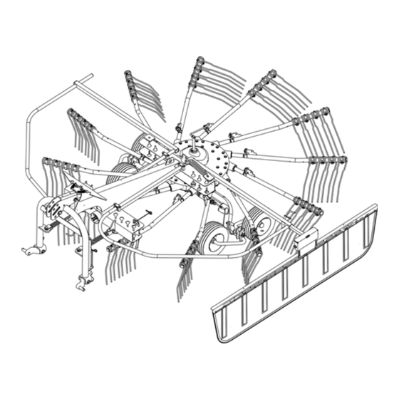
Page 12: Overview
Overview Designation of Overview components Guard bar Tine supports Rotor gear Tines Rotor chassis Main frame Transport locking bar 3-point trestle Parking stand Transport holder for Swath former Drive tine supports... -
Page 13: Crate Packaging
Overview Crate packaging Overview of assembly groups Rotor 3-point trestle Drive shaft Pendulum support Rotor chassis Tandem axle Assembly group Page »Fitting the bleed valve« »Fitting the rotor« »Fitting the 3-point trestle« »Fitting the tandem axles« »Fitting the pendulum support« »Fitting the Hydrolift«... -
Page 14: Pallet Packaging
Overview Pallet packaging 3-point trestle Pendulum support Main frame Transport locking device Rotor Rotor chassis Tandem axle Assembly group Page »Fitting the swath former«... -
Page 15: Crate Packaging
Crate packaging Requirements • Suitable flat surface approx. 10 x 10 m as assembly space. Crate packaging • Lifting gear with lifting accessories for at least 1,000 kg. • Floor conveyor (pallet truck or fork lift) • Stands for safely depositing implement parts. •... -
Page 16: Main Frame
Crate packaging Main frame Place the main frame securely on stands and secure it using suitable lifting accessories. Lifting accessories Wedge plates* Main frame Rotor gear Drive shaft Rotor chassis 3-point trestle Main frame Stands Quantity Part Main frame Rotor gear with chassis 3-point trestle Drive shaft... - Page 17 Crate packaging Fitting the bleed Remove the sealing plug from the rotor gear. valve Fit the bleed valve. Sealing plug Rotor gear Bleed valve...
-
Page 18: Fitting The Rotor
Ideal values: 85 – 115 mm (3.35 – 4.53 in) • For values other than these, fit the wedge plates between the main frame and rotor. * Wedge plates are not included in the scope of delivery. Contact Kverneland Service if the ideal values cannot be achieved. 85-115 mm... - Page 19 Crate packaging Fitting the drive shaft Positioning the main frame exactly 350 Nm 259 ft.lbs The connection between the main frame and the rotor must be positioned exactly and must be tightened to the specified torque. If it is fitted incorrectly, serious damage to the machine may be caused.
- Page 20 Crate packaging Fitting the 3-point The machine is equipped at the factory for coupling to the tractor's three-point lift support. trestle To fit the 3-point trestle: Guide the preassembled 3-point trestle to the main frame using suitable lifting accessories. ...
-
Page 21: Fitting The Tandem Axles
Crate packaging Fitting the tandem Fit the tandem axles and wheels to the rotor chassis. Ensure that the wheel carrier for adjusting the rotor pitch is on the left in relation to the axles direction of travel. Ensure that the tandem axles are aligned correctly. ... -
Page 22: Fitting The Tension Spring
Crate packaging Fitting the tension Attach the chain links to the support on the rotor gear. spring Fit the lever on the rotor chassis and secure it using a washer and dowel pin. Attach the spring to the lever. ... -
Page 23: Fitting The Pendulum Support
Crate packaging Fitting the Maintaining the installation sequence. pendulum support Observe the described sequence during the installation. Otherwise, the machine may be damaged. Fit the left pendulum support with the spring (see detailed drawings A and B). Only couple the machine to the clevises on the tractor. ... -
Page 24: Fitting The Hydrolift
Crate packaging Fitting the Fit the hydraulic cylinder for adjusting the working depth. Hydrolift Set the machine down on the rotor chassis. Grease the threaded rod and screw it into the raking wheel axle completely. Fit the circlip. ... -
Page 25: Assembling The Protective Equipment
Crate packaging Assembling the protective equipment Fitting the swath Fitting the swath former carrier. former Fit the swath former onto the swath former carrier. Swath former Swath former carrier... - Page 26 Crate packaging Fitting the guard bar Fit the lower bearing shells (see detailed drawing A). Attach the spring to the plate on the main frame (1). Place the left guard bar (4) in the lower bearing shells. ...
-
Page 27: Fitting The Hydraulics
Crate packaging Fitting the Connect and route the hydraulic hose on the Hydrolift and secure it to the main frame using cable ties (1). hydraulics Greasing schedule for PTO shafts Quantity Part Greasing interval Drive shaft 50 h Final assembly for Proceed as follows to complete the assembly: crate packaging ... -
Page 28: Pallet Packaging
Pallet packaging Requirements • Suitable flat surface approx. 10 x 10 m as assembly space. Pallet packaging • Lifting gear with lifting accessories for at least 1,000 kg. • Floor conveyor (pallet truck or fork lift) • Supports for safely depositing machine parts. •... -
Page 29: Pallet Assembly
Pallet packaging Pallet assembly Use suitable lifting accessories to lift the frame elements. Loosen all fastenings (wires, lashing straps). Secure the machine using suitable lifting accessories. Remove the transport locking devices. Extend and secure the parking stand. ... -
Page 30: Final Assembly For Pallet Packaging
Pallet packaging Final assembly for Proceed as follows to complete the assembly: pallet packaging »Crate packaging«, see page 13. »Fitting the swath former«, see page 26. »Greasing schedule for PTO shafts«, see page 27. »Adjustment work« from page 31. ... -
Page 31: Adjustment Work
Adjustment work Adjustment work Length of PTO The length of the PTO shaft was selected at the factory to suit almost all types of tractor. Only in exceptional cases is a correction of the PTO shaft shaft length required on individual tractors. Check the length of the PTO shaft on each tractor prior to first use. - Page 32 Adjustment work Shortening the PTO shaft Pull the PTO shaft apart and connect one half to the tractor PTO shaft drive and one to the machine and secure them. Place the two shaft halves next to each other and: •...
-
Page 33: Prepare The Top Link
Adjustment work Prepare the top link Only when using the optional contact roller: Remove the cover of the Top link Tool elongated hole from the top link of the 3-point trestle. Please note the following: Otherwise, damage to the machine may be caused as a result: •... -
Page 34: Machine Pitch
Adjustment work Rotor pitch Working depth Top link 20 mm (0.8 in) 0 mm Machine pitch Machine pitch For improved pick-up of the crop, use the top link to incline the Top link machine further to the front. Using the top link, incline the machine further to the front until the crop is picked up cleanly. -
Page 35: Rotor Pitch
Adjustment work Rotor pitch The rotors are inclined at an angle to the chassis so that the crop is picked up in the clearing area. The rotor is already inclined trans- versely ex-factory. If the crop is not picked up cleanly, the raking quality can be improved by adjusting the rotor pitch. -
Page 36: Tine Lifting
Adjustment work Tine lifting The time for lifting the tines can be adapted to the crop (early or late Adjusting screw lifting). The control cam (cam disc) can be infinitely adjusted. Proceed as follows: Switch off the tractor engine, put the parking brake in the park position, remove the ignition key and secure the tractor against rolling away. - Page 37 Adjustment work Basic working depth setting The crank sets the basic working depth setting. This task should only be carried out if the rotors have been completely lowered and the Crank hydraulic system is pressureless. The working depth can be controlled with Hydrolift when in operation on the field.
-
Page 38: Accessories
Accessories Additional Optional additional equipment does not form part of the standard Accessories scope of delivery, and, in this manual, is indicated by a plus equipment symbol [+]. Additional equipment is available to order from your dealer. Tine saver For a good swath deposit, both tine legs must run parallel to one another. - Page 39 Accessories Support wheel The optional support wheel on the 3-point trestle provides better contour guidance. Please note: With the optional support wheel, insert the hitch pin for the top link into the elongated hole and secure it using a safety splint.
-
Page 40: Tandem Trailing Axle [+]
Accessories Tandem trailing axle [+] The optional tandem trailing axles facilitate driving with tight cornering. Fit the contact roller. Observe the special assembly instructions. Tandem trailing axle... -
Page 41: Circuit Diagrams
Circuit diagrams Hydraulic circuit Circuit diagrams diagram Tractor hydraulics Single-acting control device Pressure line Tank line Ball valve Crank for working depth Cylinder for Hydrolift (working depth) -
Page 42: Lighting Circuit Diagram
Circuit diagrams Lighting circuit diagram 2/54g 3/31 5/58R 6/54 7/58L Connecting plug 7-pin in accordance with ISO 1724 Yellow Green White Brown Black Connector and socket 7-pin in accordance with ISO 1724 Yellow Black Right indicator Right brake light Earth Left indicator Right rear light White... -
Page 43: Final Tasks
Final tasks Trial run Final tasks No persons within the slewing range There is an extreme risk of injury within the slewing range from slewing or folding machine parts. Referring to the operator's manual, adjust the machine and carry out a trial run. - Page 44 Final tasks...
Need help?
Do you have a question about the 9542 and is the answer not in the manual?
Questions and answers