
Related Manuals for Kverneland Kultistrip


Summary of Contents for Kverneland Kultistrip
- Page 1 Kultistrip User manual Translation of original user manual Version 04.2016 Date printed 07.2020 Language Serial no. VPUCUEA11LGS06301 VPUCUEH11LGZ06301 Type Rigid & Folding Document number A135114240...
- Page 2 Copyright is held by Kverneland Group Les Landes Génusson, France. Copying, saving to another media, translating or using extracts or parts of this document is not permitted without the express consent of Kverneland. All rights reserved. The contents of these assembly instructions may...
-
Page 3: Table Of Contents
Table of contents Table of contents Preliminary information ......Maintenance ..........Onboard documents General Other applicable documents Greasing Wear rings Introduction ..........Inspection Who should read this user manual? Tine wear Meaning of symbols Wear in the fertilisation system Security ............. Disc wear For user safety Hydraulic diagrams ........ -
Page 4: Preliminary Information
Preliminary information Onboard The machine user manual is stored in the waterproof tubular Preliminary information document box fitted on the machine, generally near the coupling point. documents After reading the document, put it back in the box. This user manual is also available via https://www.kvgportal.com/publicquest/... -
Page 5: Other Applicable Documents
The machine documentation consists of this user manual, together with other documents: documents Name Description Spare parts catalogue Complete list of all spare parts available in the KVERNELAND GROUP after-sales service network. Online catalogue corresponding to the machine, available via https://www.kvgportal.com/publicquest/... -
Page 6: Introduction
Introduction Who should read this This user manual is aimed at farmers and persons trained and Introduction qualified in activities in the field of agriculture and who have received user manual? training in the use of this machine. Safety note for the user Familiarise yourself with the content of this user manual before starting up or climbing aboard the machine. -
Page 7: Security
Security For user safety This section contains general safety information. The various chapters Security in this user manual include specific safety instructions, among other things. Follow the safety instructions, in order to: • ensure your own safety, • ensure the safety of others, •... - Page 8 Security Risk of becoming caught in a rotating part of the machine (universal shaft, for example). Risk of flying stones or other items. Keep a safe distance from this part of the machine. Risk of foot amputation caused by a rotating toothed tool. Keep a safe distance from this part of the machine.
-
Page 9: Safety Rules
Security Safety rules General recommen- Prior to switching on, check that the machine complies with safety requirements and particularly that protective and safety devices (for dations example moving guards, cover, hazard stickers, etc.) are in place and functional. Before you start work, familiarise yourself with all the equipment, controls and functions on your machine. - Page 10 Security Coupling Follow the coupling instructions carefully: • when manoeuvring, select the tractor’s lowest possible forward speed, • no one should stand between the tractor and the machine when manoeuvring the tractor or during lifting operations, • the type of tractor hitch should be adapted to suit the machine’s hitch, •...
- Page 11 Security No one should enter the folding extensions area or folding or tipping (where fitted) accessories movement area, until they have been locked by the system provided for this purpose. The system may be chain, a pin, a rigid connecting rod or a double control valve. Before starting up: ...
- Page 12 Security Maintenance No work should take place within the turning circle of the tractor/tool assembly, unless the brakes or immobilisation system have been engaged. When changing parts on the machine, you should pay attention to all parts with sharp edges or corners. We recommend that safety equipment is worn (hard hat, safety shoes, gloves, etc.) For machines fitted with folding extensions, you must follow the instructions in this user manual for assembly, disassembly and...
- Page 13 Security Uncoupling There is a serious risk of injury when uncoupling the machine from the tractor! Therefore : Immobilise the tractor, never position yourself between the tractor and the machine during uncoupling, operate the tractor’s hydraulic lift slowly and carefully, ...
-
Page 14: Presentation Of The Machine
Presentation of the machine This chapter contains information on the following points: Presentation of the machine • Appropriate use of the machine, • the machine’s technical characteristics • description of the sub-assemblies comprising the machine • technical data on the sub-assemblies comprising the machine Usage clause This machine has been designed solely for normal agricultural use, i.e. -
Page 15: General Description
Presentation of the machine General Description Rigid machines Marking Designation Chassis Front signalling Coupling of the upper link bar Rear signalling Strut Coupling of the lower arms... - Page 16 Presentation of the machine Folding machines Marking Designation Chassis Folding side Front signalling Coupling of the upper link bar Rear signalling Strut Coupling of the lower arms...
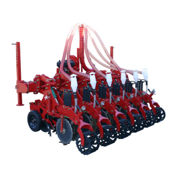
- Page 17 Presentation of the machine Rows Kultistrip row fitted with a standard tooth and fertilisation kit Marking Designation Parallelogram connecting rod Fertilisation Cyclone Roller Lateral disc Tine Waste clearer Depth control wheel Opener disc...
- Page 18 Presentation of the machine Kultistrip row fitted with a slurry tooth and slurry kit Marking Designation Parallelogram connecting rod Slurry chute Roller Lateral disc Slurry depth Waste clearer Depth control wheel Opener disc...
-
Page 19: Technical Specifications
Presentation of the machine Technical specifica- tions Rigid machines Specifications Working widths (m/ft) 3.00 ( 9’10” Transport widths 3.00 ( 9’10”) (m/ft) Distance between 45 ( ”) 50 ( 60 ( ”) 70 ( ”) 75 ( ”) 80 ( ”) 20”... - Page 20 Presentation of the machine Specifications Working widths 4.50 ( 14’9” (m/ft) Transport widths 4.50 ( 14’9” (m/ft) Distance between ar- 45 ( ”) 60 ( ”) 70 ( ”) 75 ( ”) 80 ( ”) rays (cm/in) Number of rows Tine depth ...
- Page 21 Presentation of the machine Specifications Working widths 6,00 (1 9’8” (m/ft) Transport widths 6.00 ( 19’8”) (m/ft) Distance between ar- 45 ( ”) 50 ( 60 ( ”) 70 ( ”) 75 ( ”) 80 ( ”) 20” rays (cm/in) Number of rows Tine depth ...
- Page 22 Presentation of the machine Folding machines Specifications Working widths 4.50 ( 14’9” (m/ft) Transport widths 3.00 ( 9’10” (m/ft) Distance between ar- 45 ( ”) 50 ( 60 ( ”) 70 ( ”) 75 ( ”) 80 ( ”) 20”...
- Page 23 Presentation of the machine Specifications Working widths 6.00 ( 19’8” (m/ft) Transport widths 3.00 ( 9’10” (m/ft) Distance between ar- 45 ( ”) 50 ( 60 ( ”) 70 ( ”) 75 ( ”) 80 ( ”) 20” rays (cm/in) Number of rows Tine depth ...
-
Page 24: Tine Variants
Presentation of the machine Tine variants Tines Description Standard version Slurry version Straight Little or no expansion Semi-curved Average expansion Curved Significant expansion... -
Page 25: Roller Variants
Presentation of the machine Roller variants Farmflex roller diameter 350 ( ”) [+] • Compacting / light and medium soils Cage roller diameter 350 ( ”) [+] • Compacting and crumbing / light and medium soils Cage roller diameter 350 ( ”) - Inverted roller [+] •... -
Page 26: Options
Presentation of the machine Options Signalling and lighting [+] • Signalling equipment complying with European legislation allowing movement on public roads • If necessary, refer to the machine’s spare parts catalogue to order a new lighting and signalling systems. Lateral signal kit [+] •... - Page 27 Presentation of the machine 4, 6, 8 and 12 row distribution head [+] • Distributes fertiliser evenly to all fertilising kits. Fertilising kits [+] • Incorporate the fertiliser at the desired depth (between 0 and 20 cm ) after the tines have passed. 0”...
-
Page 28: Security
Security Uncoupling Security High risk of injury when uncoupling the machine. Therefore : Immobilise the tractor, Never position yourself between the tractor and the machine during uncoupling. Slowly and carefully actuate the tractor’s hydraulic lift. Make sure that the machine is on flat and sufficiently stable ground. -
Page 29: Receipt And Assembly
Receipt and assembly Checks upon The machine may be delivered partly disassembled. In that case: Receipt and assembly receipt Check that all the parts mentioned in the assembly booklet are present. Carefully follow the instructions given in the assembly booklet. -
Page 30: Coupling
Coupling Coupling WARNING Comply fully with safety instructions. Take care always to keep a safe distance away from the machine during manoeuvres, in order to reduce the risk of crushing or becoming stuck. Rigid machines Adjust the pin on the third point bar to the desired category. Marking Designation Category 2... -
Page 31: Transport
Transport Security Transport Before travelling on roads with the machine, please read the following safety instructions carefully. Compliance with these instructions is important and helps you avoid accidents. General Before you drive on public roads with your machine: Check that you machine complies with the law and the highway code: •... -
Page 32: Switching On
Switching on Switching on WARNING • Comply fully with safety instructions. • Keep a safe distance during manoeuvres. Danger of crushing and entrapment. Any tine that is abnormally blocked in the raised position may suddenly return to its position and is therefore a source of serious danger. -
Page 33: Adjustments
Adjustments Adjustments WARNING • Comply fully with safety instructions. • Keep a safe distance during manoeuvres. Danger of crushing and entrapment. Never turn the machine with the tool in the ground. MPORTANT NOTE Working depth The working depth of the discs is controlled by the gauge wheels. Adjust the depth, while ensuring that the chassis remains horizontal during operation (parallel to the ground). -
Page 34: Adjusting The Opener Disc
Adjustments Adjusting the opener disc The opener disc opens the line ans cuts off residues to facilitate the work of the waste clearers. Lift the machine up. Stabilise the machine. Remove safety pin (A). Insert the KV key into the screw head (B), in order to make the adjustment. -
Page 35: Adjusting The Lateral Discs
Adjustments Adjusting the lateral discs The lateral discs channel the flow of earth in the row and control the width of the strip worked. For all adjustments, repeat the operation for all rows. Adjusting the spring tension: The springs provide safety in difficult working conditions. Stones or residues can cause blockages between the tooth and the lateral discs. -
Page 36: Setting The Parallelogram
Adjustments Setting the parallelogram The parallelogram allows the row to follow the terrain in order to comply with the working depths, whatever the contours. The tension in the spring is adjustable. Lift the machine up. Stabilise the machine. ... -
Page 37: Adjusting The Roller
Adjustments Adjusting the roller Depending on the roller fitted, this firms, compresses or crumbs the strip worked. Lift the machine up. Stabilise the machine. Remove the safety pin (A) on the pins (B). Lift and turn the crank handle to the desired position, using scale (C) to help •... -
Page 38: Uncoupling The Machine
Uncoupling Uncoupling • Comply fully with safety instructions. • There is a serious risk of injury when uncoupling the machine. Uncoupling the Immobilise the tractor, machine. Ensure that the ground on which the machine is resting is sufficiently stable, ... - Page 39 Uncoupling In folded position For space reasons, you may prefer to store your machine with the chassis folded using the set of storage struts. In this case: Fold up the chassis. Remove the pins from the struts. Lower the struts to a suitable position, depending on the depth of the tines.
-
Page 40: Maintenance
Maintenance Cleaning Maintenance Never use a high pressure cleaner with rotating nozzle to clean your machine. This may damage the machine. The equipment may be cleaned using a high pressure cleaner Move the water jet further away when cleaning the bearings to avoid damaging the seals and roller bearings. -
Page 41: For Your Safety
Maintenance For your safety Special safety instructions Conditions necessary for maintenance work Carry out maintenance work only if you have the necessary knowledge and tools at your disposal. Lack of knowledge or the wrong tools can lead to accidents. Use original replacement parts only original replacement... - Page 42 Maintenance Protection measures Additives mixed with oils and lubricants can be harmful to your health. Since regulations do not require manufacturers to identify these when handling oils hazards, it is essential that you follow the advice below: and lubricants Avoid contact with the skin Avoid all skin contact with these products.
-
Page 43: Maintenance
Maintenance General These notes refer to routine maintenance work. For any maintenance Maintenance work, the machine must be configured and locked in its working position. If the transport position is required for all the maintenance work, refer to the section Special safety instructions Page 41. Work done with a grease pump: ECOMMENDATIONS Lubricate with two squeezes of the grease pump If you feel resistance... -
Page 44: Greasing
Maintenance Greasing For all greasing operations, the machine must be in the park position with the tines on the ground to avoid any risk of crushing. The pictogram opposite appears next to the greasing points on the machine to enable you to locate the machine’s greasing points quickly. Folding jacks ... -
Page 45: Wear Rings
Maintenance Wear rings The wear rings must be changed when they stop protecting the different parts of the machine. If used wear rings are not replaced, damaged machine parts will not be covered by the warranty. If damaged rings are not replaced, their housing may also suffer from wear. - Page 46 Maintenance Hydraulic system for folding...
-
Page 47: Inspection
Maintenance Inspection Screwed assembly Regularly check wheel nuts for tightness and the hub clearance adjustment. All bolts must be re-tightened: • After initial use. • Depending on the intervention frequency. • At least once a season. Standard tightening Unless otherwise specified, all screwed assemblies should be tightened in accordance with the table below. -
Page 48: Tine Wear
Maintenance Tine wear Regularly check the degree of wear on coulters and fins, so that tines are not damaged prematurely. Replacing coulters Remove the pin using a pin puller. Remove the worn coulter. Fit the new coulter. ... -
Page 49: Wear In The Fertilisation System
Maintenance Wear in the fertili- sation system Replacing the fertiliser chute Undo the nuts. Remove the two screws. Remove the worn fertiliser chute Fit the new fertiliser chute Replace the screws. Re-tighten the nuts. Replacing the ... -
Page 50: Disc Wear
Maintenance Disc wear Adjusting the disc The disc height adjustment system is used to adjust for wear. Refer to height the procedure in the “Settings” section. When adjusting the discs is not sufficient to compensate for wear, they should be changed. Should such a situation arise, please contact your dealer Hubs Contact your dealer to obtain new ones. -
Page 51: Hydraulic Diagrams
Hydraulic diagrams Folding Hydraulic diagrams Non-stop release safety system... -
Page 52: Warranty
Warranty On delivery of the tool, check that all accessories are present and that Warranty no damage has occurred during transport. Any claims must be made to us in writing within six days. The guarantee will be granted only if the conditions appearing on the delivery contract have been met by the buyer. -
Page 53: Scrapping The Machine
Scrapping the machine Scrapping the machine Do not spread on the ground or pour into the sewers used grease or other substances such as motor oil, hydraulic oil, coolant fluid, brake fluid, fuel, etc. At the end of the machine’s life, it must be scrapped in accordance with environmental rules. -
Page 54: Declaration Of Conformity
Declaration of conformity In accordance with Declaration of conformity Kverneland Group Les Landes Génusson SAS directive 2006/42/EC 9, rue du Poitou FR-85130 Les Landes Génusson declare under our sole responsibility that the product Kultisrip and accessories to which this declaration relates, meets the relevant health and safety requirements in EC Directive 2006/42/EC. - Page 55 Index Index load Lubricants Assembly booklet Maintenance Manager Brake Maximum load Metal parts cage Chassis Oils Controls Online documentation Coupling Operator coupling curved Panels Parallelogram Discs Pictograms Pins Plate Equipment Public road Equipment, Reflector Farmflex registration. Fertilisation Road safety Folding jack Roller Fonctions Front axle...
- Page 56 Index tension Tightening torques Tine Transfer Transport Tyres User safety V-press warning Warranty Waste clearer...
Need help?
Do you have a question about the Kultistrip and is the answer not in the manual?
Questions and answers