Table of Contents
Advertisement
Quick Links
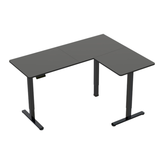
Black 63" x 47" Corner Electric Desk
SKUS: DESK-E3CTB-47
Instruction Manual
ASSEMBLY VIDEO AVAILABLE:
Follow along step-by-step with our video walk through by scanning
the QR code with your mobile device or by following the product
link: vivo-us.com/products/desk-e3ctb-47
help@vivo-us.com
www.vivo-us.com
309-278-5303
Advertisement
Table of Contents

Related Manuals for Vivo DESK-E3CTB-47


Summary of Contents for Vivo DESK-E3CTB-47
- Page 1 Black 63” x 47” Corner Electric Desk SKUS: DESK-E3CTB-47 Instruction Manual ASSEMBLY VIDEO AVAILABLE: Follow along step-by-step with our video walk through by scanning the QR code with your mobile device or by following the product link: vivo-us.com/products/desk-e3ctb-47 www.vivo-us.com help@vivo-us.com...
- Page 2 7AM - 7PM Monday-Friday Give us a Call: Chat Us: Email Us: 309-278-5303 www.vivo-us.com help@vivo-us.com We’re Here for You! Our customer-minded support team is here for YOU, Monday-Friday 7am-7pm CST. We offer immediate assistance with rapid response times from customer service agents and product techncians to...
-
Page 3: Electrical Warning
Returns | Product Didn’t Work Out? We offer a hassle-free 30 day return on all products. Contact customer support at 309-278-5303 or help@vivo-us.com. Please note: For items ordered in error or no longer needed, the return shipping charges will be at the buyer’s expense. -
Page 4: Package Contents
TOOLS NEEDED: DIFFICULTY LEVEL Phillips Screwdriver Level PACKAGE CONTENTS Please consult the parts list below and ensure you have everything you need to assemble your product. If parts are missing or damaged, please contact us. A (x1) B (x1) C (x1) D (x1) E (x1) Left Desktop... -
Page 5: Assembly Steps
ASSEMBLY STEPS STEP 1: Assemble Left Leg Connect Left Crossbar (D) to Left Leg (M) using M6x8mm Screws (S-A) and 5mm Allen Wrench (T-A). Attach Side Bracket (J) to Left Leg (M) using M6x8mm Screwns (S-A) and 5mm Allen Wrench (T-A). D (x1) M (x1) S-A (x4) - Page 6 STEP 2: Assemble Right Leg Attach Angled Right Crossbar (G) to Right Leg (K) using M6x8mm Screws (S-A) and 5mm Allen Wrench (T-A). Attach Side Bracket (J) to Right Leg (K) using M6x8mm Screws (S-A) and 5mm Allen Wrench (T-A). K (x1) G (x1) S-A (x4)
- Page 7 STEP 3: Install Feet & Connect Motorized Leg Attach Feet (P) to Right and Left Leg (K, M) using M6x35mm Screws (S-B) and 5mm Allen Wrench (T-A). Connect Short Left Crossbar (E) and Right Crossbar (F) to Motorized Leg (L) using M6x8mm Screws (S-A) and 5mm Allen Wrench (T-A).
-
Page 8: Assembly Options
- Assembly Options - This desk can be assembled with a left or right side extension. Please select an option and proceed with assembly Option A | Left Side Extension Desk frame will extend out to left side, with a short right side Pg 9-14 Option B | Right Side Extension Desk frame will extend out to right... - Page 9 ASSEMBLY OPTION A | Left Side Extension A-STEP 4: Install Anti-Vibration Pads Affix Anti-Vibration Pads (T) to desk frame and Connector Bracket (N). Insert Inner Crossbar (V) into Short Left Crossbar (E) and Left Crossbar (D). Connector Brackets (N) will be installed later. V (x1) N (x1) T (x17)
- Page 10 A-STEP 5: Assemble Desktop Connect Left, Middle, and Right Desktop (A, B, C) pieces together using Desktop Connectors (O), M5x16mm Screws (S-C) and a Phillips screwdriver. A (x1) B (x1) C (x1) O (x4) S-C (x16) Left Desktop Middle Desktop Right Desktop Desktop M5x16mm...
- Page 11 A-STEP 6: Install Connector Brackets Begin connecting frame to desktop by placing assemblies on desktop as shown below. Secure Inner Crossbar (V) using M6x11mm Screws (S-D) and 5mm Allen Wrench (T-A). Secure Connector Bracket (N) to Right Crossbar (F) and Angled Right Crossbar (G) using M6x8mm Screws (S-A) and 5mm Allen Wrench (T-A).
- Page 12 A-STEP 7: Secure Frame & Desktop Secure to desktop with M5x16mm Screws (S-C) using a Phillips screwdriver, using the screw locations shown below. Connect Control Panel (Q) to desktop using M5x16mm Screws (S-C) and a Phillips screwdriver. Q (x1) S-C (x19) Control Panel M5x16mm Screw...
- Page 13 A-STEP 8: Install Sync Rod Loosen the coupling nut on Short Sync Rod (H) and Long Sync Rod (I). Insert hex shaft from Short Sync Rod (H) into Right Leg (K) and Long Sync Rod (I) into Left Leg (M), making sure the metal retaining ring makes contact with the leg.
- Page 14 A-STEP 9: Connect Power Cables Connect AC Adapter (R) and cable from Motorized Leg (L) to Control Panel (Q). If needed, use Extension Cable (S) for cable from Motorized Leg (L) to extend length. Use Cable Clips (U) to secure cables to desktop. R (x1) S (x1) U (x2)
- Page 15 ASSEMBLY OPTION B | Right Side Extension B-STEP 4: Install Anti-Vibration Pads Affix Anti-Vibration Pads (T) to desk frame and Connector Bracket (N). Insert Inner Crossbar (V) into Angled Right Crossbar (G) and Right Crossbar (F). Connector Brackets (N) will be installed later.
- Page 16 B-STEP 5: Assemble Desktop Connect Left, Middle, and Right Desktop (A, B, C) pieces together using Desktop Connectors (O), M5x16mm Screws (S-C) and a Phillips screwdriver. S-C (x16) A (x1) B (x1) C (x1) O (x4) M5x16mm Left Desktop Middle Desktop Right Desktop Desktop Screw...
- Page 17 B-STEP 6: Install Connector Brackets Begin connecting frame to desktop by placing assemblies on desktop as shown below. Secure Inner Crossbar (V) using M6x11mm Screws (S-D) and 5mm Allen Wrench (T-A). Secure Connector Bracket (N) to Left Crossbar (D) and Short Left Crossbar (E) using M6x8mm Screws (S-A) and 5mm Allen Wrench (T-A).
- Page 18 B-STEP 7: Secure Frame & Desktop Secure to desktop with M5x16mm Screws (S-C) and a Phillips screwdriver, using the screw locations shown below. Connect Control Panel (Q) to desktop using M5x16mm Screws (S-C) and a drill. S-C (x19) Q (x1) M5x16mm Screw Control Panel...
- Page 19 B-STEP 8: Install Sync Rod Loosen the coupling nut on Short Sync Rod (H) and Long Sync Rod (I). Insert hex shaft from Short Sync Rod (H) into Left Leg (M) and Long Sync Rod (I) into Right Leg (K), making sure the metal retaining ring makes contact with the leg.
- Page 20 B-STEP 9: Connect Power Cables Connect AC Adapter (R) and cable from Motorized Leg (L) to Control Panel (Q). If needed, use Extension Cable (S) for cable from Motorized Leg (L) to extend length. Use Cable Clips (U) to secure cables to desktop. R (x1) S (x1) U (x2)
-
Page 21: Troubleshooting
CONTROLLER - USER MANUAL Memory Presets Press any number and the desk will return to the programmed height. See Programing Memory Presets to program presets. Arrow Keys Press and hold the UP arrow for the desk to begin raising. Release when desk reaches desired height. - Page 22 WHO WE ARE VIVO is more than a brand of ergonomic office furniture. We are a team of creative and innovative indivuduals working together to offer high quality, affordable ergonomic solutions. We think and work outside of the box to serve...
-
Page 23: Need Assistance
Call Us: 309-278-5303 Average Resolution Time: 5m 4s Chat Us: www.vivo-us.com Average Resolution Time: < 15m Email Us: help@vivo-us.com Average Resolution Time: 1HR 8M 23% within < 15m 38% within <... - Page 24 LOVE YOUR NEW VIVO SETUP? Ready to share that new amazing setup? Want to brag about that amazing new ergonomic solution? Tag us in your photo! VIVO-us @vivo_us FOR MORE GREAT VIVO PRODUCTS, CHECK OUT OUR WEBSITE AT: WWW.VIVO-US.COM LAST UPDATED: 04/05/2023 REV1LF...
Need help?
Do you have a question about the DESK-E3CTB-47 and is the answer not in the manual?
Questions and answers