Table of Contents
Advertisement
Quick Links
Advertisement
Table of Contents

Related Manuals for BIRO 109PC


Summary of Contents for BIRO 109PC
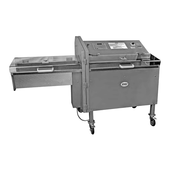
- Page 1 Model 109PC HORIZONTAL SLICER Parts List, Installation and Operating Instructions IMPORTANT SAFETY NOTICE This Manual contains important safety instructions which must be strictly followed when using this equipment. PTCT PC193-268 3-98-02-PPD...
-
Page 2: Table Of Contents
BIRO is not respo nsible for service charges or labor required to replace any part covered by this limited warranty or for any damages resulting from misuse, abuse, lack of proper or recommended service. -
Page 3: Notice To Owners And Operators
Be sure a BIRO Authorized Representative has reviewed the installation before this machine is initially started up and put into service. Contact The Biro Mfg. Co. if you do not know who is your local Biro Repre sentative. No one should use or service this machine without proper training and supervision. All opera... -
Page 4: S Afefy Tips
DO NOT Alter Machine. DO NOT Operate Machine With Missing Parts. ALW AYS Comply With all Regulations for Food Handling, Packaging, and Storing. PROMPTLY REPLACE Any Worn or Illegible Warning and Instruction Labels. ONLY USE BIRO Parts and Accessories Properly Installed. -
Page 5: Installation
NEVER Operate Without all Warning and Instruction Labels Attached. 1 . Read this Manual thoroughly before installation and operation. Do not proceed with installation and operation if you have any questions or do not understand anything in this Manual. Contact your local Distributor, or BIRO first. -
Page 6: Operation
OPERATION I A wARNINGI TO AVOID SERIOUS PERSONAL INJURY SHARP KN IFE BLAD E ONLY Properly Trained Personnel Over 1 8 Years of Age Should Use This Equipment. ALW AYS Keep Hands and All Body Parts Clear of The Cutting Area. DO NOT Tamper With, Bypass, Alter, or Modify This Equipment in Any Way From Its Original Condition. - Page 7 KEY: "START'', the "START" key will only function, if the blade door and chamber lids are closed and no fault num ber is present on the display. The cutting process is started by depressing the number, decimal or fractional, desired for the product cut thickness. The display unit then will respond by fla1?hing the LED related with THICKNESS.
-
Page 8: Machi Ne Operation
FOUR INDICATOR I.AMPS (LED's) located below the display are for indicating that the emergency stop is pushed down and/or the door and/or lids are open or a warning condition exists, which must be corrected before normal op eration may begin. PROGRAM RE CALL KEY When pressing the PROGRAM RECALL the unit will respond by clearing the display and flashing the LED associated with the PROGRAM RECALL key. - Page 9 OPTIONAL TRAILING END: At this point, the program entry may continue for the trailing end of the product. To en ter the trailing end slicing, the operator shall enter the THICKNESS. Once the trailing end slice thickness value has been entered, the operator shall press the THICKNESS/COUNT key. The keypad unit shall respond by flashing the LED associated with the PROGRAM ENTER key, flashing the LED associated with COUNT, and clearing the display unit.
-
Page 10: System Errors
C. SYSTEM ERRORS: SYSTEM ERRORS are identified by the fault codes displayed according to the type of system error as described be low: FAULT "-0-" A door and/or lid has been opened during the slicing operation. The slicing operation is stopped imme diately, even in mid slice. -
Page 11: Cleaning
CLEANING W A R N IN G ! SHARP KN IFE BLADE TO AVOID SERIOUS PERSONAL INJURY ALWAYS Turn Of f, Unplug From Power Source and Perform Lockout/Tagout Procedure to This Machine BEFORE Cleaning or Seroicing. ONLY Use Recommended Cleaning Equipment, Materials and Procedures. NEVER Spray Water or Other Liquid Substances Directly at Motor, Power Switch or any Other Electrical Components. -
Page 12: Part S Dia Grams
Hinge PC087 Optional stationary foot 14535 Foam tape gasket, per foot PC093 Rear right hand side panel 1 46 1 1 BIRO World decal, DNS PC095 Receiving chamber support bracket 14646 Disc spring PC 1 03 Side product deflector 42MC-656 Decal, 'Wired for 208 volts"... - Page 13 -------------I BLADE SHAF T ASSEMBLY ..,_ _________ ..,. PC017 C129 ss 1�l C130 P C 1 26 PC 1 2 7 HHS12 7 S � .,,- 5 (4) <6> 25S <4> v .,,- OR PC28 7 'v/30S HN40S Description Ite m No . Description Item No .
- Page 14 ITEM NO, PC182 STEPPER MOTOR AND DRIVE �SSEMBLY � HN15S P C 1 3 3 L v10s ---4 ;::: � BLK311 - --t PC206 PC006 / / H HN20S � PC016 ..----- P C 1 8 5 --�•� ,) \ PC184 FHS4 3 S PC0S2 �...
- Page 15 ITEM ND, PCl 95 PRODUCT PUSHER ASSEMBLY TO PRODUC T PUSHER COMPONENT PLATE ASSEMBLY ITEM ND. PC189 Item No. Description Hex head screw, 5 / 15 - 18 x 7 / a , SS msosas S p rin g hous i n g ..
- Page 16 P C 0 0 7 � I T E M NO. P C 1 8 9 2 7 2 - 8 � P R O D U C T P U S H E R � COMPONENT PLATE A S S ' Y PC188 P C 0 4 7 BLK311...
- Page 17 CDNRDL BOX & COVER ASSE MBLY 2 41-L N-�� 25-1 HHS060S � / ,,,, I ' , ,, ,, ..\ \JlOS ,, ,,;,, " .,,, .,,,, ,,,, .,,,, " ,, ,, .._ .,,,, ✓ .,,, .,,,, • ,, ,, " l\JlOS �...
- Page 18 ---------------I PC202 ITEM ND. ELECTRICAL COMPONENTS ASSEMBLY .,_ __ ____ ____ _ _ 208-230-460V/60HZ/3PH P C 1 4 2 H H S 0 1 2 S P C 1 5 3 L \J 0 5 S P C 1 8 1 H N l 0 S P C 1 4 7 P C 1 3 5...
-
Page 19: Wiring Diagram: 208/230/460V-60Hz-3Ph
f3- - - - - r .. -·· 1 �---·-1··=---r .. ----1 10;, v 1 G:';, v i CPTDW. toTU tTIUP ! � v ! � v i � v i � � l◄V.1,DOVATI &;_ J � l � l ·... - Page 20 Tl & T2 TRANSFORMER WIRING 208/220/230/240 VOLTS N0.26 TO #1 ON SOLI D - S T A T E R E L A Y N0.36, TO BRAKE X1.I DONGAN ELECTRIC CD. TRANSF"llRM!:R !80 VA. !30-460V PRIHARY (2) 7.:SV, C2> 17.5V, 9,0V, 48V SECONDARY N0.2 T O Kl CONTAC TOR L3 T l T R A N S F O R M E R F D R A 2 0 8 V O L T A G E...
-
Page 22: Wiring Diagram: 380/415V-50Hz-3Ph
l-------------- ITEM NO , PC204 - - ------------..ELECT RICAL C O MPONE N T S ASSEMBLY 380 - 4 1 5V /50HZ/3PH P C 1 5 3 P C 1 4 6 P C 1 8 1 PC1 4 7 P C 1 5 2 PC135 PC043... - Page 23 ----- ,;-·- � , -- 7 l 0 i �JMW ' • • � v • � i � ,_ � v j L�_n __ J � � - JL _ _ l�OlblEJt CDKCTltNS "l"' ,--- - : ! :� DRJVER BOARD I T EM NO.
- Page 24 Tl & T2 TRANSFORMER WIRING 380/41 5 VOLTS N0.26 TO #1 ON SOLID-STATE RELAY N0.2 TD Kl CONT ACTOR L3 X1.1 D□NGAN ELECTRIC CO. TRANSf'□RMER VA. 230-◄60V PRIMARY (2 ) 7.SV, (2 ) 17.5V, 9.0V, 48V SECONDARY 0.3, TD Hl, T2 TRANSFORMER T l T R A N S F O R M E R F D R A 3 8 0 V O L T A G E N0.26 TD #1 ON SOLID-STATE RELAY...
-
Page 25: Wiring Diagram: Stepper Motor, All Voltag Es
STEPPER MOTOR WIRING ALL VOLTAGES RED \./IRE INCOMING ,--- PERMANENT MOTOR \./IRE \./IRES REFERENCE ONLY □\./ ATTACH YELL \./IRE _.,... BLACK \./IRE HERE PERMANENT MOTOR \./IRE REFERENCE ONLY ATTACH GREEN \./IRE HERE ATTACH BLUE \./IRE HERE □\./ YELL \./IRE -r-i- PERMANENT MOTOR \./IRE REFERENCE ONLY ORANGE \./IRE PERMANENT MOTOR \./IRE... -
Page 26: Maintenance
NEVER Bypass, Alter, or Modify This Equipment in Any Way From Its Original Condition. PROMPTLY REPLACE Any Wom or Illegible Labels. USE ONLY GENUINE BIRO Parts and Accessories Properly Installed. A. TIMING ADJUSTMENT Remove the rear panel. Look to the right for a proximity switch (Telemecanique brand) , pointing at a locking collar attached to the main blade drive shaft. - Page 27 B L ADE S H A R P B E V E L S I D E RES T I N G P O S I T I O N B L A D E T I M ING ADJUSJMENT I L L U S T R A T I O N ..-----1/2 (1 2.?MM) t o...
-
Page 28: Component Plate - Product Pusher Adjustment
B. COMPONENT PLATE - PRODUCT PUSHER ADJUSTMENT Lift the loading chamber cover. The product pusher must move freely by hand with 20 to 25 lbs. force. With electrical power "OFF", move the product pusher by hand to the left approx. 6" ( 1 53mm). - Page 29 c \JlOS .,,.. L\J15S .."11D HN20S � HN20S P C 1 2 2 ., � L\Jl5S F\JlOS HHS055S-- COMPONENT PLATE ITEM NO, PC089 IF THE COMPONENT PLATE CAN ROCK LEFT TO RIGHT. THE FRONT 2 V-ROLLER NEED AJUSTMENT, ADJUSTABLE FRONT V-ROLLERS CLEAN AND RE-GREASE OR SILICONE SPRAY SQUARE GUIDE BAR...
-
Page 30: Electrical
C. ELECTRICAL Electrical Supply: Is the machine grounded? The 1 09PC requires a ground line. Check each incoming electrical line to ground. Record voltage readings: L 1 to ground - L2 to ground - L3 to ground Is one of the three electrical lines to ground higher or lower (voltage reading)? If it is, that electrical line must be attached to L2 in the electrical enclosure. -
Page 31: Limited Warranty
D. TROUBLE SHOOTING PC BOARDS A. 250ma fuses blow out on CPU board. Reason: Flat ribbon cable was disconnected from the driver board assembly. B. There is no display LED's "ON" or number on display board. Reason: The bottom 250ma fuse blew and/or the 1 .25 A fuse blew. C. -
Page 32: Recommended Spare Parts List
RECOMMENDED SPARE PARTS LIST ITEM NO. DESCRIPTION QUANTITY BUG l l BEARING, 9MM SLIDE WASHER, PRODUCT PUSHER PC005 PC007 BEARING SHAFT, PRODUCT PUSHER PC025 FASPIN, PRODUCT PUSHER PC054 DRNEN TIMING PULLEY, 5MM PITCH, 30 TOOTH PC055 ROLLER, PRODUCT PC1 24 Bl.ADE, SMOOTH BLADE.
Need help?
Do you have a question about the 109PC and is the answer not in the manual?
Questions and answers