
Related Manuals for BIRO B350 Comfort


Summary of Contents for BIRO B350 Comfort
- Page 1 B350Comfort NSF 8-2010 SINGLE SPEED AUTOMATIC FEED SLICER INSTALLATION, USE, MAINTENANCE & PARTS MANUAL MAY 11, 2016...
- Page 2 DECLARATION OF CONFORMITY A.B.M. COMPANY S.r.l. Via Rho, 6 – 20020 LAINATE MI – Italia Model: B350 COMFORT s/n: ___________________________ I0804009 Compliant to NSF/ANSI Standard 8: Commercial powered food preparation equipment. *EN 60204-1 Machines electrical equipments *EN 60335-2-64 Particular requisition for kitchen machines...
- Page 3 SLICING MACHINES AUTOMATIC VERSION B350 COMFORT This manual consists of 29 pages as follows: • Title page with notes for the user; • Contents, page 3; • Page 4 to page 28 carrying progressive numeration Pag. 1...
-
Page 4: Table Of Contents
CONTENTS FOREWORD SCOPE OF THIS MANUAL GENERAL INFORMATION LIMITS OF USE – SAFETY NORMS GENERAL SAFETY REGULATIONS MANUFACTURER’S WARRANTY AND LIABILITY PLATES – CONFORMITY MARKS ENVIRONMENTAL CONDITIONS OF USE PACKING OPENING THE BOX TECHNICAL DESCRIPTION AND PROPOSED CONDITIONS OF USE GENERAL DESCRIPTION MECHANICAL AND ELECTRICAL SAFETY DEVICES WARNING: RESIDUAL RISKS... -
Page 5: Foreword
FOREWORD SCOPE OF THIS MANUAL This manual contains all the necessary information to install, use and service the gravity slicers for food (please see models in paragraph “Technical Description”). The scope of this document, hereinafter the “manual”, is to permit users, and especially end users, to take all the cautions and provisions possible for using this machine safetly and for a long time. -
Page 6: Manufacturer's Warranty And Liability
MANUFACTURER’S WARRANTY AND LIABILITY The manufacturer’s warranty covering the functioning of the machines and their complian- ce to the service for which they have been designed depends on the correct application of the instructions contained in this manual. The Manufacturer assumes no liability either direct or indirect deriving from: •... -
Page 7: Packing
PACKING OPENING THE BOX On receipt, check packaging integrity, otherwise inform the forwarding agent or the area agent immediately. To unpack the machine, proceed as follows: • Open the box and remove your copy of the manual of use and maintenance, then proceed according to the instructions found in that manual;... -
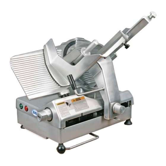
Page 8: Technical Description And Proposed Conditions Of Use
TECHNICAL DESCRIPTION AND PROPOSED CONDITIONS OF USE GENERAL DESCRIPTION The machine is essentially made of a base supporting a circular blade mounted in tilted position. This blade is driven by an electrical motor to slice food. The machine is equipped with a carriage holding a product tray and sliding on tracks mounted under the base top, parallel to the blade. -
Page 9: Dimensions Main Technical Data
DIMENSIONS MAIN TECHNICAL DATA AUTOMATIC GRAVITY SLICERS MODEL UNI 350 COMFORT MODEL motor Kw 0,30 motor Kw blade diam 14" blade diam slice thickness 0 - 1" 0 - 25 slice thickness ס ס 9"1/4 max cut max cut mm □... -
Page 10: Main Components
MAIN COMPONENTS gravity version CODE DESCRIPTION DOUBLE START SWITCH STOP SWITCH THICKNESS KNOB CARRIAGE SUPPORT CARRIAGE HANDLE CARRIAGE PUSHER HANDLE SHARPENER GAUGE PLATE BLADE GUARD BLADE FRAME TRANSMISSION COVER MANUFACTURER IDENTIFICATION PLATE MACHINE DATA AND UE MARKS SUPPORT FOOT Pag. 9... -
Page 11: Machine Commissioning And Function Tests
MACHINE COMMISSIONING AND FUNCTION TESTS INSTALLING THE MACHINE Position the machine on a well leveled, smooth and dry top suitably dimensioned to with- stand the machine weight. ELECTRICAL CONNECTION Install the machine near a compliant outlet derived from a system meeting the current norms. - Page 12 COMMANDS START AND STOP BUTTONS • Green button (1): first push to start running the blade (green light). second push to start running the carriage (blue light). • The light turns on to indicate that the machine works correctly. • Press the red button to stop the machine completely (2) Slice thickness can be adjusted by turning the graduated knob (3) anti clockwise.
-
Page 13: Using The Machine
USING THE MACHINE LOADING THE PRODUCT ON THE TRAY AND SLICING Lift the gripper arm Lock the gripper arm into the rest position as shown in photo B Pag. 12... - Page 14 Unscrew the fence retaining knob and slide the fence in to the outer position 1. Load the product on to the meat platform 2. Slide the fence against the product 3. Lock the fence in place firmly using the locking knob Pag.
- Page 15 Locate the gripper arm onto the product Select the thickness of the product to be sliced using the portion thickness control knob Pag. 14...
-
Page 16: Cleaning The Slicer
CLEANING THE SLICER GENERAL The machine must always be accurately cleaned at least once a day, and more often if necessary. Always use protective gloves. DISASSEMBLING THE MACHINE FOR CLEANING • Disconnect the plug from the mains; • Turn the gauge plate to ‘0’; •... - Page 17 • Stop the machine, rotate the adjustable knob to regulate the gauge plate and position it on 0 (1) • Return the carriage to the operators side (2) • Turn the knob (3) anti clockwise, until loose, the carriage will then drop back for cleaning (4).
- Page 18 UNSCREW THE BLADEGUARD ROAD (1), than remove the cover blade (2) Carefully insert the doth betwen the knife and Carefully wash the top and bottom the knife ring guard. While holding the cloth of the knife by wiping from the cen- between the knife and the ring guard, work it ter of the knife outward.
-
Page 19: Desassembling The Guide Bar For Cleaning
DESASSEMBLING THE GUIDE BAR FOR CLEANING 1. Unscrew the knob 2. Remove the bar 3. Removable parts ready for cleaning REASSEMBLE THE SLICER: PROCEED AS INDICATED FOR THE PREVIOUS OPERATIONS BUT IN REVERSE ORDER Pag. 18... -
Page 20: Cleaning The Slicer Underneath - Lifting Device
CLEANING THE SLICER UNDERNEATH - LIFTING DEVICE 1. Move the carriage forward 2. Lift the machine by using the proper lever 3. Clean underneath LIFT DOWN THE MACHINE BY USING THE PROPER LEVER Pag. 19... -
Page 21: Cleaning And Sanitizing The Blade
CLEANING AND SANITIZING THE BLADE • Disconnect the plug from the mains; • Turn the gauge plate to ‘0’; To clean the machine body and the blade use only a cloth damped with water and biodegradable lathery detergent having 7-8 pH and at a temperature not below + 86°F. -
Page 22: Reassembling The Machine
A thorough visual inspection should be made of the entire slicer and its parts. Biro urges the owner / operator to inspect all components often, including ones that are the thetachable for cleaning and sanitizing. This inspection should include: loocking for damaged parts, brocken seals or gaskets, and areas that may be more difficult to clean and sanitize. -
Page 23: Blade Sharpening
BLADE SHARPENING - Versions with NOT INTEGRED sharpener Before proceeding, carefully clean the machine as explained in the previous paragraphs: Sharpening can be done only up 0,5 inches of the blade diameter value. Beyond this value, the BLADE MUST BE REPLACED ONLY by personnel AUTHORI- ZED BY THE MANUFACTURER. - Page 24 3) Move thickness regulator to the 25 mm position. This opens the blade to the desired position ready for positioning the sharpener. 4) Meat plate positioned in the middle. Pag. 23...
- Page 25 5) The small recess on the gauge plate is for the positioning of the sharpening mechanism Verify the correct position 6) Start blade rotating Pag. 24...
- Page 26 7) Turn dial to position 1. This will sharpen the rear of the blade. Run for 20", turn dial to position 2 for 5". This will take the burr of the front surface of the blade. 6) Stop the machine. Remove the sharpener and SANITIZE the blade before using the machine again.
-
Page 27: Lubrication
BIRO 350GCO Recommended Spare Parts 2016 EDITION B350 GCO : Z9MAF AF01US Sharpening stone Sharpener Z9MSB Cleaning stone G111-A Water-ring protection G8CIN Z9PIE Trasmission Belt Foot Z14AMR Single phase card 115V-60Hz Z13AMR Single phase card 220V-50Hz MODEL 350 3rd GEN. :... -
Page 28: Dismantling The Slicer
BIRO B 350 GCO AUTOMATIC SLICER STANDARD 8 - 2010 G432 VT191 Z3PMS G100 G119 VT233 VT230 G257 G362T G361T Z9PIE VT324 G9314 VT409 G361T VT168 CODE DESCRIPTION VT123 G100 FRAME G119 SLIDE ROD - 25 x 578 G2500 BRACKET -SWIT CH... - Page 29 BIRO B 350 GCO AUTOMATIC SLICER STANDARD 8 - 2010 VT349 VT387 Z3ATQ VT479 Z5L3G VT333 G120 G105B G0100 X0491 VT442 X0360D G111-A VT417 VT396 G125 VT209 X0620A G111-B VT135 VT460 CODE DESCRIPTION G9369 G117B G9369 BLADE GUARD ROD - ASSEMBLY...
- Page 30 BIRO B 350 GCO AUTOMATIC SLICER STANDARD 8 - 2010 G124 VT440 G131 VT124 VT084 VT010 Z9GHI VT423 Z4BCN VT005 Z8MGRA25 CODE DESCRIPTION G124 CAM INDEXING 25mm + VT440 G131 SPACER CAM VT005 SPACER RING d. 18-25x1 SS VT010 SPRING WASCHER d. d.18.5-32x0.3 BLACK...
- Page 31 BIRO B 350 GCO AUTOMATIC SLICER STANDARD 8 - 2010 G0170 VT126 VT210 X0270 W6CUS Z8BCN G132 G110 VT096 G122 VT127 G102 VT442 F9331500 VT208 VT127 X0450 G132 VT442 VT096 CODE DESCRIPTION G9361A SLIDE INDEX ASSEMBLY (G102+Z8BCN+VT442) F9331500 SPRING d 10 L 55...
- Page 32 BIRO B 350 GCO AUTOMATIC SLICER STANDARD 8 - 2010 G101 G1022 G112 CODE DESCRIPTION G101 GAUGE PLAT E G1021 G1021 SS PLAT E ST RENGT HENING VT128 G1022 LOCKING PLAT E SCREW VT106 G112 GAUGE PLAT E PROT ECT ION VT 106 ACORN HEX CAP M10-1.5 SS...
- Page 33 BIRO B 350 GCO AUTOMATIC SLICER W7CUS STANDARD 8 - 2010 X0272 X0271 Z9BCR Z9FUN ZZRMT VT127 VT087 X0261 VT086 X0210 VT104 X0230F VT127 VT087 VT011 G104 X0240F Z5BCN VT040 VT442 VT414 X0120 VT085 X0250 VT040 G116 VT447 Z5BCN X0110...
- Page 34 BIRO B 350 GCO AUTOMATIC SLICER STANDARD 8 - 2010 VT442 G356 G357 G360 F9331500 X0450 G365 G365 G359 G358 G139 VT126 VT328 VT126 VT328 VT352 G417 G353 G355 G353T G355T G354 CODE DESCRIPTION G417 SPRING F9331500 SPRING d 10 L 55...
- Page 35 BIRO B 350 GCO AUTOMATIC SLICER STANDARD 8 - 2010 G137 VT127 VT105 G118 VT088 VT128 G415 G419 VT104 G412 VT095 G114 Z8MBPA VT398 G113 CODE DESCRIPTION G113 SHAFT PIVOT RETURN G114 LOCKING CARRIAGE PLATE G118 KNOB SHAFT G137 REGULATION SHAFT...
- Page 36 BIRO B 350 GCO AUTOMATIC SLICER STANDARD 8 - 2010 G397 G136 G406 G407 G9NOT G9363 G303 G422 CODE DESCRIPTION G136 ALU KNOB G303 KNOB - LOCKING FENCE ASSEMBLY G397 SLIDE ROD ASSY G406 CARRIAGE T RAY G407 FENCE SHAFT...
- Page 37 BIRO B 350 GCO AUTOMATIC SLICER STANDARD 8 - 2010 G138 C2092 G0160A VT479 G138 Z3BCN G409 Z3BCN VT449 C2043 VT104 G425 VT460 VT460 C2080 G425 VT126 G9NOT G142 C2080 CODE DESCRIPTION X0363 GRIP HOLDER ASSEMBLY ( G409+C2080+G9NOT+G425+VT460+Z3BCN ) C2043...
- Page 38 BIRO B 350 GCO AUTOMATIC SLICER STANDARD 8 - 2010 G368C G368 G34701T G93135 VT136 VT335 VT087 VT238 VT407 Z27AMR G349T G442 VT458 VT193 G361T G443 G362T G363S CODE DESCRIPTION G34701T SLIDING PLATE G349T MOTOR GEAR FLANGE G361T SS PIVOT SPACER 20x96 M8...
- Page 39 BIRO B 350 GCO AUTOMATIC SLICER G371Z29 STANDARD 8 - 2010 VT085 G207 VT461 VT125 F9308200 G209 VT126 G208 W9CUS PA42 W8CUS G312 VT348 G364Z29N VT016 G378 G3500N G214 CODE DESCRIPTION G214 PIN ASSEMBLY F9308200 RET AINING RING EXT ERNAL M20 SS...
- Page 40 BIRO B350 GCO AUTOMATIC SLICER STANDARD 8 - 2010 AF021 G393 Z6BCN VT435 G270 Z6BCN AF025 VT126 VT104 CODE DESCRIPTION ø AF021 KNOB 40 M10 AF025 PLASTIC WHEEL G270 LEVER SPACER G393 LIFT LEVER VT104 ACORN HEX CAP M6-1.0 SS...
-
Page 41: Motor Assembly
BIRO B350 GCO AUTOMATIC SLICER ZZATP STANDARD 8 - 2010 G106 FROM S/N 80416 F9308200 G8CIN FROM S/N 80416 W2CUS W2CUS G108D X0060 W6CUS X0070 M9315 W6CUS M9313 M9314 M9310 MOTOR ASSEMBLY M9381 115V/60 Hz IP65 FROM S/N 80416 M9382 220V/50 Hz IP65 FROM S/N 80416... - Page 42 BIRO B 350 M MANUAL SLICER STANDARD 8 - 2010 X0720 Z3CON 220V-50-60Hz Z14AMR Z8CON 115V-60Hz 115V-60Hz Z9PLK Double Start Switch Z13AMR 220V 50-60Hz Z9PLH Stop Switch VT192 Z9CON 220V-50-60Hz VT125 Z6CON 115V-60Hz X0710 CODE DESCRIPTION VT125 FLAT WASHER M5 SS VT192 HEX HEAD SCREW M5-0.8x10 SS...
- Page 43 BIRO AUTOMATIC SLICER STANDARD 8 - 2010 AF062 ZZVOL AF076-AF077-AF078-AF079 AF07200-AF07201-AF07202-AF07203 AF07301-AF07302-AF07303 VT194 VT134 AF025 VT134 VT194 VT085 AF064-AF065-AF066-AF0661 AF068-AF069-AF070 VT134 VT194 VT194 VT134 CODE DESCRIPTION VT085 AF025 PLAST IC WHEEL AF067 AF062 PLAST IC SHARPENER DEVICE AF064 SEP. SHARP. FOOT B300 M GAP 15mm AF065 SEP.SHARP.
- Page 44 BIRO AUTOMATIC SLICER STANDARD 8 - 2010 AF040 AF036 AF039 AF038 AF035 AF011 Z2BCN Z9MAF AF007SXA AF018 AF008SX AF020 AF074 Z9MSB AF063 AF018 Z2BCN AF008SX AF007SXA CODE DESCRIPTION AF007SXA SHAFT ASSEMBLY ( AF006 + AF007SX) AF008SX NUT - SPECIAL AF011...
- Page 45 BIRO B 350 GCO AUTOMATIC SLICER STANDARD 8 - 2010 VT480 96XXAA02 G439 VT435 G440 CODE DESCRIPTION 96XXAA02 WHIT E PLAST IC RIVET G439 LABEL FOR LUBRIFICATION G440 T UBE FOR LUBRIFICATION VT 480 NAIL VT435 HEX SOCKET SET SCREW CUP POINT M5-0.8x5 SS...
- Page 48 THE BIRO MANUFACTURING COMPANY 1114 W. Main Street Marblehead, OH 43440 USA Ph. 419-798-4451 Fax 419-798-9106 Email: service@birosaw.com ...
Need help?
Do you have a question about the B350 Comfort and is the answer not in the manual?
Questions and answers
What does the knob that holds the platform up screw into
The knob on the BIRO B350 Comfort screws into a shaft assembly, as indicated by the part "AF007SXA SHAFT ASSEMBLY (AF006 + AF007SX)" in the provided context.
This answer is automatically generated