
Related Manuals for Fresenius Kabi Agilia VP MC WiFi


Summary of Contents for Fresenius Kabi Agilia VP MC WiFi
- Page 1 Agilia VP MC WiFi Volumetric Infusion Pump For Healthcare Facilities Instructions For Use Valid for software version 2.6 Page: 1 of 222...
- Page 2 Symbols Description Symbols used in this document Warning of a potential hazard that could result in serious personal Recommendations to be followed. injury and/or product damage if the written instructions are not followed. _________________________________________________________________________________ Labelling symbols Warning Name and address of the (Refer to the Instructions For Use) manufacturer / Date of manufacture Caution: Federal law restricts this...
- Page 3 Agilia VP Infusion System, please report this to your local Fresenius Kabi representative or submit a request to the Fresenius CERT (cert@fresenius.com). See the Agilia VP MC WiFi Technical Manual, for more on how to protect against cybersecurity threats, including: ...
- Page 4 Notes, page 220. WARNING The Agilia VP MC WiFi should be used to deliver medications where it is clinically acceptable to be given using an infusion pump. Refer to the medication product insert for details on infusion routes for the adequate programming of the infusion pump (e.g.: rate, pressure...
- Page 5 Hyperbaric chamber High humidity environments (e.g. shower, bath, etc.) Agilia VP MC WiFi is MR Unsafe. WARNING The functionality of the pump can be affected by pressure variations, mechanical shocks, heat ignition sources, and other unusual events.
- Page 6 WARNING If you stop the pump prior to initiating a Programmed bolus, the pump will not resume after the Programmed Bolus has been delivered. The pump will remain in the stop mode until you resume the infusion. If the infusion is not resumed within 30 seconds the pump will alarm, Waiting Start.
- Page 7 WARNING If the alarms persist when the pump is powered on again, do not use the device on a patient, and contact qualified biomedical engineering staff in your healthcare facility, or your Fresenius Kabi representative. Page: 7 of 222...
- Page 8 WARNING Only use recommended Volumat Lines. Use of any other administration sets may affect the accuracy of the infusion, and result in injury to the patient and damage to the pump. Do not use an administration set if its packaging appears to be damaged or opened.
- Page 9 Pumps must be plugged into a medical grade power strip if one is used. WARNING The use of another cable may lead to PC / Agilia VP MC WiFi infusion pump malfunctions and electrical harm due to residual leakage currents. ...
- Page 10 WARNING Use of the Agilia pump adjacent to or stacked with other equipment should be avoided because it could result in improper operation. If such use is necessary, this equipment and the other equipment should be observed to verify that they are operating normally. ...
-
Page 11: Table Of Contents
Table of Contents INTRODUCTION ....................18 COPE ..................18 NTENDED 1.2.1 Intended routes of administration ............19 ..............19 RINCIPLES OF PERATION ............19 NTENDED RODUCTS TO BE NFUSED ..................20 NTENDED SERS ..............20 ATIENT HARACTERISTICS ................21 ONTRAINDICATIONS ..............21 NSPECTION EQUIREMENTS ................21 NVIRONMENT AGILIA CONNECT INFUSION SYSTEM ............23 GILIA ONNECT... - Page 12 INSTALLATION ..............35 CCESSORY NSTALLATION ............36 SING THE OTATING LAMP ) ..............38 TTACHING THE PUMP GETTING STARTED ..................40 LOWCHART ..........40 SING THE UMP FOR THE IRST ..................41 OWERING ON .......43 NSTALLING THE DMINISTRATION ET IN THE ..................44 EIGHT OPERATION ..................46 LOWCHART ................47 ELECTING A ROFILE...
- Page 13 7.10.3 Advancing an Air Bubble ..............88 7.10.4 Auto-restart..................90 7.10.5 Pre-programming the Pump ............... 91 MENUS ....................92 VERVIEW ....................94 ROFILE ....................95 RESSURE (VTBI) ............99 OLUME NFUSED ................100 EYPAD TATUS ..............102 EYPAD UTOMATIC ..................104 ATTERY ............104 OLUME NFUSED NFUSED ....................106 AUSE 8.10 ....................108...
- Page 14 10 DATA COMMUNICATION 10.1 ..................127 VERVIEW 10.2 ...........128 OMMUNICATION VIA GILIA ABLES 10.3 ..............129 OMMUNICATION VIA 10.4 ................129 PLOAD 10.5 ..............130 NFRARED OMMUNICATION 11 USER TEST 12 ALARMS AND SAFETY FEATURES 12.1 ..................132 NTRODUCTION 12.2 ................132 LARM ESCRIPTIONS 12.3 ................133 ENERAL EMARKS 12.4...
- Page 15 15.7 ...................159 ETECTION 15.8 ..............159 RESSURE ANAGEMENT 15.9 ..................161 CCURACY 15.10 I ........168 NFUSION OF BLOOD AND BLOOD DERIVATIVES 15.11 C .................169 ALCULATION ULES 15.12 U ............169 NITS AND ONVERSION ULES 16 CLEANING AND LOW LEVEL DISINFECTION 16.1 ...............171 NSPECTION EQUIREMENTS 16.2 ....171...
- Page 16 19.2 .................193 PECIFICATIONS 19.2.1 Electromagnetic Compatibility ............193 19.2.2 WiFi Quality of Service ..............194 19.2.3 WiFi Data Integrity................194 19.2.4 WiFi Troubleshooting guide.............. 195 20 TROUBLESHOOTING 21 WARRANTY 21.1 ............198 ENERAL ARRANTY ONDITIONS 21.2 ................198 IMITED ARRANTY 21.3 ........198 ARRANTY ONDITIONS FOR CCESSORIES...
- Page 17 25 GLOSSARY OF TERMS APPENDIX: FACTORY CONFIGURATION INDEX Page: 17 of 222...
-
Page 18: Introduction
Introduction Scope These Instructions For Use (IFU) are applicable to the Agilia VP MC Volumetric Infusion Pump. The user must adhere to the instructions specified in this IFU or other accompanying documents including quick reference guide. Failure to adhere to these instructions may result in damage to the equipment, injury to patients or injury to users. -
Page 19: Intended Routes Of Administration
Agilia VP MC WiFi can be used for intermittent or continuous infusions. Agilia VP MC WiFi is intended for use on only one patient at a time. It can be reused indefinitely on multiple patients throughout its lifetime. Intended Products to be Infused The pump administers products through clinically accepted routes. -
Page 20: Intended Users
The Agilia VP MC WiFi should be used for only fluids intended for infusion pumps. Do not use the pump for epidural use. -
Page 21: Contraindications
If you see discoloration, cracks or other damage, return the pump to Biomedical Engineering for repair. Use Environment Agilia VP MC WiFi is intended for use in healthcare facilities, under the supervision of trained healthcare personnel. The pump must be used in the following operational conditions to ensure proper performance: ... - Page 22 INFORMATION For more information on using the device in specific conditions, contact your Fresenius Kabi representative. INFORMATION Please wear gloves when using Agilia VP MC WiFi. Page: 22 of 222...
-
Page 23: Agilia Connect Infusion System
Pumps designed to deliver the contents of a bag or bottle through a line connected to a patient. Medication Safety Solution Drug Library Software designed to create, customize and manage data sets to be uploaded to the Agilia VP MC WiFi infusion pump. Server Software Drug Library... -
Page 24: Description
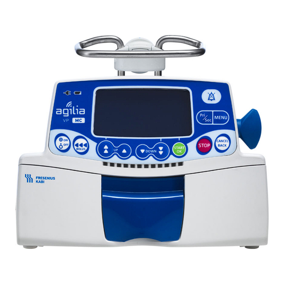
Description Front View Legend Handle Pump Door Door Lever Figure 3.1: Front View Bottom View Legend Slot for pump stacking Device Identification Label Figure 3.2: Bottom view Device Identification Label: Figure 3.3: Example of Device Identification Label Page: 24 of 222... -
Page 25: Back View
On the device identification label, the UDI (Unique Device Identifier) is presented in machine-readable form (AIDC - Automatic Identification and Data Capture - technology) and as text: (01) Product Identifier GTIN (21) Product Serial Number (11) Date of Manufacture ... -
Page 26: Keypad
Keypad 3.4.1 Keypad Description Figure 3.5: Keypad Legend 3 13 Screen Increment Cancel Value / Move Back to Previous Field 3 14 Battery Charge Status Infusion Indicator Lights Menu Indicator (LED) (LED) 3 7 9 3 15 Power Supply Indicator Decrement Primary / Secondary (LED) - Page 27 3.4.2 Keypad Details 3.4.2.1 Selection Keys Description Arrow Keys Keys for selecting values for volume, time, flow rate and other values Fast Access to Maximum Value or Top of a List Fast Access to Minimum Value or Bottom of a List Note: ...
-
Page 28: Display And Symbols
3.4.2.3 Status Indicators Indicator Description Power Supply Indicator (LED) When the device is attached to an active power supply, the indicator light is a constant green. If the pump is not connected to the AC power, it does not light up. Battery Charge Status Indicator (LED) When the device is attached to an active power supply, the indicator light provides information about battery charge status:... - Page 29 Symbol Description WiFi status WiFi signal strength: high WiFi signal strength: medium WiFi signal strength: low No WiFi signal (WiFi enabled). WiFi deactivated. 3.5.3 Navigation Buttons Symbol Description start Start Confirm enter Access Function New ? Access Function and Clear Current Settings exit Exit Function...
-
Page 30: Packaging
Data Communication Symbol Description Data Set Loaded A new data set has been loaded to the pump. Packaging The Agilia VP MC WiFi packaging contains the following: 1 Agilia VP MC WiFi pump 1 Instructions For Use manual ... -
Page 31: Fundamentals
Fundamentals Profiles A profile defines the device configuration and drug library used for a group of patients in a given healthcare environment. By default, factory settings include only 1 profile (Basic Profile). Custom profiles can be created and loaded to the pump using a compatible Drug Library Software. -
Page 32: Custom Profiles
4.1.2 Custom Profiles Custom profiles can be configured and loaded to the pump using a compatible Drug Library Software. A custom profile contains the following: a specific device configuration (pump settings that control the mechanical functions of the pump (i.e. alarm volume) ... -
Page 33: Drugs
Drugs 4.3.1 Infusion Rates A drug in a drug library must specify the infusion rate: Flow rate: Infusion of a volume over a period of time Dose rate: Infusion of a specific amount of a drug over a period of time 4.3.2 Drug X (mL/h) -
Page 34: Infusion Modes
4.3.4 Infusion Modes An infusion can be started according to the following modes: Infusion Rate Infusion Mode Description Flow Rate Dose Rate Volume / Time / Rate This infusion mode gives access to the 3 infusion (V/T/R) parameters (V, T, R) Infusion defined by a total volume, a total infusion time, a ramp-up and ramp-down time and a plateau Ramp-up / Ramp-... -
Page 35: Installation
Installation Accessory Installation A pump can be installed on any of the following: Location Comments See section 5.3.1, page 38. Pole Pole specifications: Diameter: from 0.6 to 1.6 in (15 to 40 mm) See section 5.3.2, page 38. Rail Rail specifications: ... -
Page 36: Using The Rotating Pole Clamp
Do not use accessories that appear to be damaged. For more information on accessories, refer to their respective accompanying documents. WARNING The pump must be used in a horizontal and stable position to function properly. Use recommended Agilia accessories to ensure stability and prevent the pump from falling. - Page 37 5.2.2 Using the Rotating Pole Clamp Secure the rotating pole clamp vertically or horizontally by folding it outward until the release button clicks into the locked position. 5.2.2.1 Folding the Clamp Down (outward) Fold the clamp down as follows: 1. Push the release button. 2.
-
Page 38: Attaching The Pump(S)
Attaching the pump(s) 5.3.1 Attaching to a Pole 1. Fold the pole clamp down to the horizontal position: see section 5.2.2.1, page 37. 2. Unscrew the clamp, attach to the pole, and screw the clamp until the pump is fully secured to the pole. 3. - Page 39 5.3.4 Attaching Pumps Together You can attach up to three non-infusing pumps together for transport, two infusing pumps. Note: The diagram below describes attaching two pumps together. 1. Fold both pumps’ pole clamps up: see section 5.2.2.2, page 37. 2.
-
Page 40: Getting Started
Getting Started Flowchart Once the pump is installed at the bedside, you must follow the steps below in order to install an administration set and power on the pump. Preparing the administration set and the fluid container section 13.1, page 146. Priming the administration set section 13.2, page 148. -
Page 41: Powering On
Powering on INFORMATION The pump can operate using the battery; however, we recommend that the pump be connected to a power supply as often as possible during use in order to ensure that the battery remains charged. When the pump is connected to the power supply, check that the power supply indicator (LED) lights up green. - Page 42 Screen After Powering on Description The OCS checks and confirms the correct functionality of the pumping mechanism, pump door, pumping fingers, pumping membrane, downstream pressure sensor, and “SafeClip.” This system is the main mechanism for providing safety from free-flow. ...
-
Page 43: Installing The Administration Set In The Pump
Installing the Administration Set in the Pump WARNING During all manipulations of the pump with administration set (administration set installation, door opening, administration set removal), close the roller clamp and make sure the line is closed. INFORMATION Do not open the roller clamp until the OCS test has successfully completed. -
Page 44: Pump Height
Pump Height WARNING Ideally, the volumetric pump should be level with the distal tip of the catheter (e.g., the site of fluid delivery; if accessing a central line the volumetric pump should be at the level of the patient’s heart). If the pump height is raised relative to the distal tip of the catheter (e.g., during internal facility transport), the increase in height of the volumetric pump can result in a temporary increase in fluid delivery or bolus until the flow... - Page 45 Precautions for pump position If using multiple volumetric pumps and it is not clinically feasible to have all pumps level with the distal tip of the catheter (or the site of fluid delivery), place the high risk or life-sustaining medications as close to level with the distal tip of the catheter as possible.
-
Page 46: Operation
Operation Flowchart Selecting a Profile section 7.2, page 47. Basic Profile Custom profile section 4.1.1, page 31. section 4.1.2, page 32. Selecting a Drug section 7.3, page 48. Flow rate Dose rate Programming Programming section 7.4.1, page 49. section 7.4.2, page 51. Starting an Infusion section 7.5, page 59. -
Page 47: Selecting A Profile
Selecting a Profile INFORMATION Profile selection screen is displayed if more than one profile is available. Profile selection step is only possible at pump start up. Once a profile is selected, you must power OFF and then ON the pump to switch from one profile to another. -
Page 48: Selecting A Drug
Selecting a Drug After selecting a custom profile, you must select a drug to infuse. Drugs are sorted alphabetically by the first letter of their names: A C J S ... -
Page 49: Programming An Infusion
Programming an Infusion Reminder The Agilia VP Infusion System is intended for adult and pediatric care for the intermittent or continuous delivery of parenteral fluids, medications, blood and blood derivatives through clinically accepted parenteral routes of administration. These routes of administration include intravenous, intra-arterial, subcutaneous and intraosseous, using dedicated administration sets. - Page 50 1. Press the arrow keys to program the Volume to be Infused (VTBI) and press OK. INFORMATION Press to select the pre-defined VTBI from values: 0.1 mL, 10 mL, 20 mL, 50 mL, 100 mL, 250 mL, 500 mL, 1000 mL, 1500 mL. ...
-
Page 51: Programming An Infusion By Dose Rate
2. Press the arrow keys to program the flow rate, and press OK. Entry of a flow rate automatically calculates the duration. If duration has been programmed, you can press OK to confirm flow rate. 3. After confirming, you will reach Confirmation screen. 4. - Page 52 Legend Unauthorized Range Authorized Range Authorized Concentration Range Hard Limits Default Value Finite Values Authorized Finite Concentrations Selecting the Drug Concentration Range Finite values 1. Press the arrow keys to select the concentration. 2. Press OK to confirm. 7.4.2.2 Selecting the Patient’s Characteristics Weight Body Surface Area 1.
- Page 53 INFORMATION The weight entry screen only appears if the selected drug uses weight for dose rate calculations. The body surface area entry screen only appears if the selected drug uses body surface area for dose rate calculations. Pre-populated default weight or body surface area are configured with a compatible Drug Library Software.
- Page 54 1. Press the arrow keys to program the infusion duration (_h_min), and press OK. The dose rate is automatically calculated. Duration programming can also be skipped by pressing OK to reach Dose field. 2. Press the arrow keys to program the dose rate, and press OK. ...
-
Page 55: Programming A Loading Dose
7.4.3 Programming a Loading Dose Note: This feature can be enabled or disabled with a compatible Drug Library Software. If enabled for the selected drug, you can program a loading dose after programming an infusion defined by dose rate. The screens below will appear prior to starting the infusion. - Page 56 1. Press the arrow keys to enter a value for the dose, and press OK to confirm. 2. Press the arrow keys to program the loading dose duration (_h_min_s), and press OK to confirm. Single arrow increases seconds, double arrow increases minutes. Increasing to 60 minutes converts to 1 hour....
-
Page 57: Programming Beyond Soft Limits
Interrupting a Loading Dose 1. To Stop the loading dose, press . The screen displays Continue? 2. Choose one of the following options: Press no or to stop the loading dose and proceed to the programmed primary infusion. Press start to continue with the loading dose. - Page 58 Flow rate Dose rate 2. Press OK to confirm values. Flow rate Dose rate 3. Carefully review the program settings. 4. If the displayed settings correspond to the intended flow rate or dose rate, press OK. Flow rate Dose rate 5.
-
Page 59: Starting An Infusion
Starting an Infusion 1. Check the administration set integrity. 2. Check that no air remains in the administration set. 3. Confirm that the administration set is correctly installed in the pump. 4. Open the roller clamp. 5. Connect the administration set to the patient's access device. 6. -
Page 60: Monitoring An Infusion
Monitoring an Infusion 7.6.1 Monitoring an Infusion when Programmed by Flow Rate Legend Custom Profile Icon Infusion Duration (Dur.:) When infusing a drug selected At the current rate, the remaining from a drug library, this infusion time in hours and minutes. lighthouse icon is displayed on Infusion duration may or may not be the screen continuously. - Page 61 7.6.2 Monitoring an Infusion when Programmed by Dose Rate Legend Custom Profile Icon Infusion Duration (Dur.:) When infusing a drug selected At the current rate, the remaining from a drug library, this infusion time in hours and minutes. lighthouse icon is displayed on Infusion duration may or may not be the screen continuously.
-
Page 62: Functions During Infusion
Functions During Infusion 7.7.1 Stop Flow rate Dose rate To stop the infusion, press . After 30 seconds, an alarm is generated as a reminder that the infusion is stopped. To restart the infusion, first confirm or modify the programming settings, then start the infusion. -
Page 63: Secondary (Piggyback) Infusions
7.7.3 Secondary (Piggyback) Infusions A secondary infusion delivers the contents of a secondary bag or bottle, by connecting a secondary line to the upstream access port of the primary line. When the secondary infusion is complete, the return to primary infusion can be done manually or automatically, depending on the Basic profile configuration and Drug Library Software Profile settings. - Page 64 INFORMATION Specific administration sets are available for secondary infusions. For more information, refer to the instructions on the administration set packaging. It is recommended to use a primary administration set with a back check valve above the upper access port. 7.7.3.2 Accessing Secondary Infusion 1.
- Page 65 7.7.3.3 Programming Secondary Infusion 1. Select a secondary drug (only when using a custom profile) and press OK. Press the arrow keys to program the secondary VTBI, and press OK. INFORMATION The secondary infusion default soft and hard limits for flow rate as well as minimum, default and maximum limits for VTBI are defined for each medication.
- Page 66 INFORMATION Pri VI indicates the total primary volume infused since it was last cleared or since a new primary drug was started. Sec VI indicates the total secondary volume infused since it was last cleared or since a new secondary drug was started. 7.7.3.4 Secondary Infusion Start 1.
- Page 67 7.7.3.5 End of Secondary Infusion INFORMATION The near end of infusion alert is not available in secondary infusion. 7.7.3.5.1 Manual Return to Primary Infusion 2. Press to silence the alarm. 3. Answer the question Continue sec ? Press Yes to program another secondary infusion. ...
- Page 68 6. Press start to resume primary infusion. 7.7.3.5.2 Automatic Return to Primary Infusion At the end of secondary infusion, a short beep is emitted. A notification message is displayed (optional). 1. Ensure that the primary clamp is open. 2. Press to acknowledge the message.
- Page 69 7.7.3.5.3 Discontinue Secondary To manually return to primary infusion prior to the end of a Secondary infusion: 1. Stop Secondary infusion with Stop key. 2. Press Pri/Sec key or press Menu and scroll to find P/S menu. 3. Enter P/S menu. 4.
-
Page 70: Administering A Bolus
7.7.4 Administering a Bolus INFORMATION For very low-volume boluses (less than 5 mL for sets with filters and less than 1 mL for sets without filters) at maximal sustainable flow rates, see section "15.9.3 Bolus Volume Accuracy" on page 164. A bolus is an extra dose or volume that a pump can deliver from the current infusion. - Page 71 INFORMATION The bolus volume is added to the Volume Infused (VI). Total volume infused (including bolus volume) will not exceed the VTBI of the programmed infusion. Both Programmed and Direct Boluses are available for primary infusions. Direct Bolus is not available in the Basic Profile.
- Page 72 Occlusion Pressure Level during a bolus is set to 750 mmHg/100 kPa/14.5 PSI. INFORMATION Programmed Bolus parameters can be adjusted at the bedside within limits defined by a compatible Drug Library Software (Custom Profile). Basic Profile Programmed Bolus volume defaults to 0.1 mL on the pump, this can be adjusted at the bedside in accordance with the prescription.
- Page 73 Programming a Bolus 3. Press the arrow keys to program the bolus volume or dose, and press OK. 4. Press the arrow keys to program the bolus duration (_h_min_s), and press OK. The flow rate is calculated automatically. Flow rate Dose rate 5.
- Page 74 Initiating a Programmed Bolus without resuming the infusion 1. Stop the infusion Press the key and select Programmed bolus. 2. Press the arrow keys to program the bolus volume or dose, and press OK. 3. Press the arrow keys to program the bolus duration (_h_min_s), and press OK....
- Page 75 WARNING If you stop the pump prior to initiating a Programmed Bolus, the pump will not resume after the Programmed Bolus has been delivered. The pump will remain in the stop mode until you resume the infusion. If the infusion is not resumed within 30 seconds the pump will alarm, Waiting Start.
- Page 76 Notes: The bolus volume infused will be displayed on the pump’s screen. The infusion resumes its programmed rate after the bolus key is released. Direct bolus is administered while the bolus key is depressed. Direct Bolus will stop when the key is no longer depressed or the volume limit for the Direct Bolus is reached (whichever occurs first).
-
Page 77: Completing An Infusion
Completing an Infusion 7.8.1 Near End of Infusion Alert Note: This feature can be enabled or disabled with a compatible Drug Library Software (custom profiles) or in the pump options (Basic Profile). For more information, refer to the technical manual. Prior to the end of an infusion, a near end of infusion alert is automatically triggered. -
Page 78: End Of Infusion
7.8.2 End of Infusion After completion of the VTBI, the pump alarms and issues End of Infusion alarm. 1. End of Infusion with KVO disabled 2. End of Infusion with KVO enabled Keep Vein Open (KVO) - KVO rate starts at the completion of a primary infusion (VTBI to zero), the infusion will continue at the KVO rate configured or whichever is lower. - Page 79 Addressing End of Infusion with KVO disabled to silence the alarm. 1. Press Pump is silenced for: 15 seconds when using a compatible Drug Library Software (Custom Profiles) 2 minutes in Basic Profile. 2. Pump displays programming screen: Drug selection when using a compatible Drug Library Software (Custom Profiles) Infusion programming in Basic Profile.
- Page 80 KVO Specifications Basic Profile Custom Profile(s) Yes, by profile in the compatible Configurable Yes, pump menu Drug Library Software Default Setting Disabled/OFF Disabled/OFF 1-20 mL/h 1-20 mL/h Flow rate (mandatory field) (mandatory field) 1 to 5 minutes 1 to 5 minutes ...
-
Page 81: Powering Off
Addressing End of Infusion with KVO enabled Infusion complete, VTBI is zero. 1. Press to silence the alarm. 2. When alarm silenced, the pump transitions to the KVO Infusing screen. The infusion indicator lights (LEDS) display 2 ON yellow and 2 ON green. -
Page 82: Additional Infusion Modes
Additional Infusion Modes You can program an infusion with the different infusion modes available, depending on the pump configuration, and on the selected drug. To select an infusion mode, see section 8.15, page 113. For more information on calculation rules, see section 15.10, page 168. 7.9.1 Volume / Time / Rate (V/T/R) For more information, see section 7.4, page 49. - Page 83 3. Press the arrow keys to program the VTBI, and press OK. 4. Press the arrow keys to program the total infusion duration (_h_min), and press OK. 5. Press the arrow keys to program the ramp-up duration (_h_min), and press OK. 6.
-
Page 84: Sequential Infusion
7.9.2.2 Stopping the Ramp-up / Ramp-down infusion 1. During the infusion plateau, press and choose one of the following actions: Press to start the ramp-down. Press back to cancel the previous action (pressing ), and return to the infusion screen. ... - Page 85 3. Press OK to program sequence 1, or the down arrow key to move to sequence 2. 4. Follow the instructions in the table below to program the desired sequence. Note: When the sequence number is selected, press the down arrow key to move to the next sequence.
-
Page 86: Other Functions
INFORMATION To modify a sequential infusion, see section 8.17, page 115. You can only modify a sequence that has not started yet. 7.10 Other Functions 7.10.1 Priming the Administration Set Note: This feature can be enabled or disabled with a compatible Drug Library Software (custom profiles) or in the pump options (Basic Profile). -
Page 87: 7.10.2 Air-In-Line Conditions
5. Press and hold the key to prime, or press cancel to cancel. 6. To end priming, release the key. 7. Make sure there is no air in the administration set. INFORMATION Priming is only accessible prior to starting the infusion. ... -
Page 88: 7.10.3 Advancing An Air Bubble
7.10.3 Advancing an Air Bubble Note: This feature can be enabled or disabled with a compatible Drug Library Software (custom profiles) or in the pump options (Basic Profile). An air-in-line alarm is triggered when an air bubble is detected by the air sensor. - Page 89 4. Press and hold to advance the air past the air detector. 5. Restart the infusion, or press cancel to cancel the advance air bubble function. INFORMATION Use of the Advance Air Bubble function is intended to allow the clinician to view the size of the air bubble in the administration set.
-
Page 90: 7.10.4 Auto-Restart
7.10.4 Auto-restart Auto-restart is an optional feature that alters the pump’s response when a downstream occlusion is detected. The auto-restart feature can be enabled or disabled with compatible Drug Library Software (custom profiles) or by using the pump options (Basic Profile). INFORMATION When the alert Wait during pressure measurement checking is displayed, wait while the downstream line pressure normalizes: the... -
Page 91: 7.10.5 Pre-Programming The Pump
INFORMATION When infusing with critical drugs or on vulnerable patients (such as young pediatric patients), pay special attention to configuring Auto- restart to meet clinical requirements. 7.10.5 Pre-programming the Pump You can program the pump before installing the administration set. 1. -
Page 92: Menus
Menus Overview 8.1.1 Commands Operation Access menu or exit menu Select Confirm (corresponds to enter on the screen) Select / Deselect 8.1.2 Menu Description Stop Infusion Menu Symbol Associated Procedure Required Profile Displaying active profile information, page 94. ... - Page 93 Stop Infusion Menu Symbol Associated Procedure Required Switching between day mode and night mode, Day/Night mode page 110. Programming a secondary infusion or returning Primary / Secondary to a Primary infusion, page 112. Programmed bolus Programming a bolus, page 112. ...
-
Page 94: Profile
Profile Symbol Procedure Displaying active profile information Stop Infusion Required INFORMATION If current Profile is not correct, turn the pump OFF and ON again to access Profile selection. You can display the active profile name as follows: 1. Press 2. Press the arrow keys to select Pro . 3. -
Page 95: Pressure
Pressure Symbol Modifying the pressure threshold (occlusion alarm) and pressure Procedure threshold modes Stop Infusion Required 8.3.1 Configuring the Pressure Threshold Mode Prior to Use When the downstream line pressure exceeds the pressure threshold, the pump triggers a downstream occlusion alarm. The pump offers one of two user modes for setting pressure thresholds: ... - Page 96 8.3.2.1 Recommended Initial Pressure Threshold Settings The following table shows the initial recommended Pressure Threshold settings for different infusion flow rates: Target Infusion Expected Time to Detect Recommended Flow Rate Pressure Threshold Downstream Occlusion 0.1 mL/h 50 mmHg 46.5 ±...
- Page 97 3. Press enter to access the Occlusion pressure screen. 4. Press the arrow keys to increase or decrease the pressure threshold. 5. Press OK to validate. 6. Press to enable or disable the Auto-restart function (optional). Press OK to confirm. To review the Auto-restart setting, see section 15.8, page 159.
- Page 98 8.3.2.4 Responding to Occlusion Alarms When the alarm pressure threshold is reached, an occlusion alarm is triggered: you must silence the alarm, resolve the occlusion and restart the infusion. If there is no occlusion, see on page 98. When addressing or clearing an occlusion: WARNING Ensure the fluid flow to the patient is clamped to prevent administering an unintended bolus.
-
Page 99: Volume To Be Infused (Vtbi)
Volume To Be Infused (VTBI) Symbol VTBI Procedure Changing VTBI Stop Infusion Required You can change the VTBI as follows: 1. Press 2. Press the arrow keys to select VTBI . The active VTBI is displayed. 3. Press enter. 4. Press the arrow keys to modify the VTBI. 5. -
Page 100: Keypad Lock Status
Keypad Lock Status Note: This feature can be enabled or disabled with a compatible Drug Library Software (custom profiles) or in the pump options (Basic Profile). Symbol Procedure Locking / Unlocking the keypad Stop Infusion Required You can use this feature to avoid inadvertent key presses. Depending on the device configuration the keypad lock and unlock code can be enabled or disabled. - Page 101 Unlocking the Keypad You can unlock the keypad as follows: 1. Press 2. Press the arrow keys to select 3. Press enter. 4. If a code is required, press the keys to enter the unlock code. The keypad is unlocked. 5.
-
Page 102: Keypad Automatic Lock
INFORMATION keys remain functional when the keypad is locked. During keypad lock, the key is functional when the infusion is stopped. During keypad lock, the key is functional when an alarm occurs, or at the end of infusion. ... - Page 103 You can enable the Keypad Automatic Lock as follows: 1. Press 2. Press the arrow keys to select 3. Press enter. 4. Press the arrow keys to set the Automatic lock to "yes". 5. Press OK. The keypad will lock automatically at infusion start. If the keypad is unlocked during the infusion, it will lock again automatically after a configured time-out.
-
Page 104: Battery Life
Battery Life Symbol Procedure Viewing the battery life Stop Infusion Required You can view the battery life as follows: 1. Press 2. Press the arrow keys to select . The time remaining under current flow rate conditions is displayed. The bar graph shows a visual representation of battery life. The symbols displayed on the screen indicate the following: ... - Page 105 1. Press to enter the menu list. This action can be done during an active infusion or when the infusion is stopped. 2. Scroll with arrow keys to select mL? . 3. To access the VI / DI information, press enter. 4.
-
Page 106: Pause
Pause Symbol Procedure Programming a pause Stop Infusion Required You can program a pause as follows: 1. Press to stop the infusion. 2. Press 3. Scroll the menu list with the arrow keys to select 4. Press enter. 5. Press the arrow keys to program the pause duration in hours and minutes, and press OK. - Page 107 6. Select yes with any arrow key to automatically restart infusion at pause end. OR Keep no for the pump to wait for user action at pause end. 7. Press OK to begin the programmed pause. To restart the infusion before the end of the pause period. Infusion delayed - Automatic resume Pause - Manual resume INFORMATION...
-
Page 108: Drug
8.10 Drug Symbol Procedure Changing the drug selection Stop Infusion Required You can change the drug selection as follows: 1. Press to stop the infusion. 2. Press 3. Press the arrow keys to select 4. Press enter. 5. Press OK to confirm. 6. -
Page 109: Patient
INFORMATION Changing a drug resets the infusion settings. If the previous infusion was programmed by flow rate, the new drug’s confirmation screen will display VI (Volume Infused). If the previous infusion was programmed by dose rate, the new drug’s confirmation screen will display DI (Dose Infused). -
Page 110: Day/Night Mode
8.12 Day/Night Mode Note: This feature can be enabled or disabled with a compatible Drug Library Software (custom profiles) or in the pump options (Basic Profile). Symbol Procedure Switching between day mode and night mode Stop Infusion Required This function switches between day mode and night mode The default night mode settings are as follows: ... - Page 111 to enable night mode. 4. Press The screen displays 5. Press OK to confirm. Note: Pressing any key when the pump is in night mode will illuminate the screen display for 30 seconds. In case of alarm, pump will automatically switch from night to day mode. Switching from Night Mode to Day Mode You can switch to day mode as follows: 1.
-
Page 112: Primary / Secondary
8.13 Primary / Secondary Symbol Programming a secondary infusion or returning to a Primary Procedure infusion Stop Infusion Required To program a secondary infusion, see section 7.7.3, page 63. 8.14 Programmed Bolus Symbol Procedure Programming a bolus Stop Infusion Required To program a bolus, see section 7.7.4, page 70. -
Page 113: Mode
8.15 Mode Mode Symbols Procedure Changing the infusion mode Stop Infusion Required You can change the infusion mode as follows: 1. Press 2. Press the arrow keys to select Mode . The infusion mode currently applied is displayed. 3. Press enter. The available infusion modes are displayed. -
Page 114: Ramp-Up / Ramp-Down
8.16 Ramp-up / Ramp-down Symbol Procedure Modifying a ramp-up/ramp-down infusion Ramp-up/ramp-down infusion mode must be selected, see section Prerequisite 8.15, page 113. Stop Infusion Required You can modify the ramp-up /ramp-down infusion settings as follows: 1. Press 2. Press the arrow keys to select 3. -
Page 115: Sequential Infusion
8.17 Sequential Infusion Symbol Procedure Modifying a sequential infusion Sequential infusion mode must be selected, see section 8.15, Prerequisite page 113. Stop Infusion Required You can modify the sequential infusion settings as follows: 1. Press 2. Press the arrow keys to select seq . 3. -
Page 116: Alarm Volume
8.18 Alarm Volume Symbol Procedure Adjusting the alarm volume Stop Infusion Required You can adjust the alarm volume as follows: 1. Press 2. Press the arrow keys to select 3. Press enter. 4. Press the arrow keys to select the alarm volume. The pump emits an alarm at the selected volume level. -
Page 117: View Flow Rate History
8.19 View Flow Rate History Symbol Procedure Viewing flow rate history Stop Infusion Required This function allows the user to check the current infusion’s history information in order to verify the dose administered. You can view flow rate history as follows: 1. -
Page 118: View Pressure History
8.20 View Pressure History Symbol Procedure Viewing pressure history Stop Infusion Required This function allows the user to check the current infusion’s history information in order to verify changes in pressure. You can view pressure history as follows: 1. Press 2. -
Page 119: View Event Log
8.21 View Event Log Symbol Procedure Viewing the event log Stop Infusion Required The event log displays details of the last events that occurred on the pump. Events are stored in the log even after the pump is powered off and on again. -
Page 120: Date/Time
6. Press exit to return to the previous screen. 8.22 Date/Time Symbol Procedure Setting up the date and time Stop Infusion Required You can set the date and time as follows: 1. Press 2. Press the arrow keys to select 3. -
Page 121: Maintenance
8.23 Maintenance Symbol Procedure Displaying maintenance information Stop Infusion Required You can display maintenance information as follows: 1. Press 2. Press the arrow keys to select 3. Press enter. 4. Press the arrow keys to scroll through the maintenance information. The following information is displayed: ... -
Page 122: Library Information
8.24 Library Information Symbol Procedure Displaying drug library information Stop Infusion Required You can display drug library information as follows: 1. Press 2. Press the arrow keys to select . The number of drugs contained in the drug library is displayed. 3. -
Page 123: Clinical Information
8.25 Clinical Information Symbol Procedure Viewing remaining time before clinical information display Stop Infusion Required If configured for the selected drug with a compatible Drug Library Software, a protocol message will be displayed on the pump’s screen after a pre-defined period of time. You can view the remaining time before clinical information display as follows: 1. -
Page 124: Data Set
8.26 Data Set Symbol Procedure Displaying active data set information Stop Infusion Required You can display active data set information as follows: 1. Press 2. Press the arrow keys to select DS . 3. Press enter. The active data set information is displayed. Page: 124 of 222... -
Page 125: Options
Options Commands Operation Options access Option selection Confirm (corresponds to enter on the screen) Select / Deselect Selected current values are stored when the device is powered off after programming. To return to the normal menus, power off then power on again. Option Descriptions Four different option groups are available on the pump. -
Page 126: Pump Settings
Pump Settings The following options have different functions that you can enable or disable to customize your Agilia VP MC WiFi. Default Function Choice Pump Setting Maintenance: display or hide maintenance Disabled [User 2]: menu Menu items ... -
Page 127: Data Communication
Before connecting the pump to a hospital information system, ask your IT or biomedical department to configure the device. To prevent unauthorized connections to the Agilia VP MC WiFi Volumetric Infusion Pump (cybersecurity threats), do as follows: Always disable the serial communications port when it is not in use ... -
Page 128: Communication Via Agilia Cables
Kabi Representative. 10.2.2 Using the Communication Port How to connect the cable: 1. Remove the protective cap from the Agilia VP MC WiFi infusion pump’s RS232 communication port. 2. Connect the cable to the RS232 communication port by tightening the cable nut completely. -
Page 129: Communication Via Wifi
10.3 Communication via WiFi The WiFi option allows the pump to connect to a hospital information system. To enable or disable the WiFi, see section 9.3, page 126. ([User 14]: WiFi Module). INFORMATION WiFi pumps can be configured with WiFi enabled or disabled. ... -
Page 130: Infrared Communication
10.5 Infrared Communication The Infrared Communication option is not available in the US. Page: 130 of 222... -
Page 131: User Test
User Test The following protocol provides the user with a quick integrity check guide to ensure that the pump system is functional. Perform this user test before each use of the pump. 1. Check the external appearance of the pump for the absence of cracks or other visible damage. -
Page 132: Alarms And Safety Features
Alarms and Safety Features 12.1 Introduction Agilia VP MC WiFi has a continuous monitoring system that begins when the pump is started. When an alarm is triggered, a message is displayed on the pump’s screen. WARNING Audible alarm signals from medical devices may be masked by environmental noise. -
Page 133: General Remarks
Required Alarm Priority Operator Description Response The infusion continues. The infusion indicator lights (LEDs) yellow are ON. The pump emits audible alarm signals. Low (!) Awareness Depending on the alarm, the key silences the alarm for no time limit or for a defined duration. For detailed description of each alarm, please refer to List of Alarms, page 134. -
Page 134: List Of Alarms
12.4 List of Alarms 12.4.1 Installed Set Alarms Stops Message Priority Alarm Trigger Problem / Resolution Infusion? At start-up, the administration set is not loaded or the door is open. Install the administration set When a set is and close the door. properly There is no administration set in installed,... - Page 135 Stops Message Priority Alarm Trigger Problem / Resolution Infusion? Air bubble: detection of air stops infusion Air alarm: while An air bubble has been detected infusion is (at start-up, during the infusion, or running, while the infusion is stopped). configured Air bubble !!! ...
- Page 136 12.4.3 Infusion Alarms Stops Message Priority Alarm Trigger Problem / Resolution Infusion? Remaining VTBI One of the near end of infusion (0 to 50 mL) alert criteria is reached (time or remaining before the end of infusion, % of infusion duration VTBI remaining, remaining VTBI).
- Page 137 Stops Message Priority Alarm Trigger Problem / Resolution Infusion? The flow rate (or dose rate) has User been modified using the keys, but reprogrammed / has not been confirmed. modified an Check the flow rate (or dose Check Medium (!!) infusion settings !! rate) and press OK to confirm.
- Page 138 Stops Message Priority Alarm Trigger Problem / Resolution Infusion? Pump reaches end of secondary VTBI and user silenced the end of secondary End of secondary infusion with alarm Check that manual return to primary infusion. Low (!) primary clamp is Note: pump is ...
- Page 139 12.4.4 Pressure Alarms Stops Message Priority Alarm Trigger Problem / Resolution Infusion? The pressure in the upstream line is too low. "X" indicates an upstream occlusion. Sensor detects that upstream blockage reaches pressure limit (infusion Upstream High (!!!) pressure is occlusion !!! Check line for closed clamps or getting closer to...
- Page 140 Stops Message Priority Alarm Trigger Problem / Resolution Infusion? Sensor detects that down-stream blockage reached pre- alarm pressure limit: In-line pressure has reached 50 mmHg / 5 kPa / 1 PSI below - alarm threshold between the programmed threshold. 76 mmHg and 750 mmHg, 50 mmHg below the current...
- Page 141 Stops Message Priority Alarm Trigger Problem / Resolution Infusion? The pressure is decreasing in the infusion line. This warning can be Measured selected as an option. pressure value is Check the downstream inferior to Drop in Low (!) Luer lock connection and the pressure ! configured limit integrity of the entire line.
- Page 142 12.4.5 Battery Alarms WARNING When the pump is not connected to the power supply a Medium-Priority Battery Alarm will sound 30 minutes prior to a High-Priority Battery Alarm. If the pump is still not connected to the power supply after the High-Priority Battery Alarm the pump will turn OFF after 5 minutes.
- Page 143 12.4.6 Power Alarms Stops Message Priority Alarm Trigger Problem / Resolution Infusion? The power supply is inconsistent. Power supply Contact your technical support. AC power Low (!) failure: multiple failure ! interruptions Note: the key silences the alarm. The pump is disconnected from the AC power.
- Page 144 12.4.8 Technical Error Alarms WARNING If the alarms persist when the pump is powered on again, do not use the device on a patient, and contact qualified biomedical engineering staff in your healthcare facility, or your Fresenius Kabi representative. Stops Message Priority...
-
Page 145: 12.4.9 Technical Low Priority Alarm
12.4.9 Technical Low Priority Alarm Stops Message Priority Alarm Trigger Problem / Resolution Infusion? Temperature increase. Check the environment, move Temperature limit from direct sun light or other High internal Low (!) exceeded heat sources. temperature ! (≥ to 65 °C) Note: the key silences the alarm for 2 minutes. -
Page 146: Volumat Lines
Volumat Lines 13.1 Preparing the Administration Set and the Fluid Container Volumat Lines are supplied sterile and are indicated for single use. 1. Prepare the fluid container according to your healthcare facility’s protocol. 2. Select a Volumat Line. 3. Check the container, the line and access device integrity. - Page 147 Precautions for the use of administration sets Use administration sets which have the smallest internal volume or priming volume (“deadspace”) to minimize residual volumes when administering medications or fluids at low infusion rates (e.g., less than 5mL per hour, and especially flow rates less than 0.5 mL per hour).
-
Page 148: Priming The Administration Set Manually Before Use
13.2 Priming the Administration Set Manually Before Use The administration set is primed with fluid to displace air from the set. It is recommended to prime the administration set immediately before starting the infusion. Certain administration sets may require specific priming procedures. Refer to the Volumat Line label. - Page 149 1. Close roller clamp. 2. Remove cap from spike, insert spike into bag 3. Hang bag and fill drip chamber to approx. 1/2 full. 4. Open roller clamp slowly for priming. Invert needle-free port while priming and gently tap valve to remove all air and prime set.
- Page 150 13.2.2 With a Bottle The following diagram shows how to prime the administration set with a bottle: 1. Close the roller clamp. 2. Check that the air vent is closed and push the spike down into the bottle. 3. Hang the bottle upside down, then squeeze and release the drip chamber in order to fill it approximately 1/2 full.
-
Page 151: Other Uses Of Administration Sets
13.3 Other Uses of Administration Sets 13.3.1 Access Ports The administration set may be equipped with access ports, that can be used to connect a gravity line, a secondary line, or administer a manual bolus (needle-free port). Figure 13.2: Needle-Free Ports Legend Upstream port (before the pump) Downstream port (after the pump) - Page 152 Figure 13.3: Gravity Infusion (in parallel with a pump) INFORMATION Fresenius Kabi recommends the use of a back check valve or positive pressure infusion device when an infusion on the pump is connected to a gravity line. This will prevent the back-up of IV fluid or medication into the gravity line.
-
Page 153: Removal And Replacement Of Administration Sets
13.4 Removal and Replacement of Administration Sets 13.4.1 Removing an Administration Set 1. Press to stop the infusion. 2. Close the roller clamp. 3. Open the pump door. 4. Press to silence the audible signal for 2 minutes. 5. Remove the administration set from the pump. 6. -
Page 154: Device Storage, Transport, And Recycling
Device Storage, Transport, and Recycling 14.1 Precautions for Storage Handle the device with care during storage. Store the device in a cool, dry place. The storage area should be clean, organized and secured against unauthorized access. Clean and disinfect the device prior to storage. WARNING If the device is not used for an extended period (longer than 1 month), it is recommended that the battery be removed from the device and put in... -
Page 155: Using The Device After Storage
They must be collected separately and disposed of according to local regulations. INFORMATION For more information on waste processing regulations, contact your Fresenius Kabi representative or the local distributor. Follow healthcare facility policy regarding proper disposal, at end of pump life. Page: 155 of 222... -
Page 156: Specifications
Specifications INFORMATION The range of settings and default values described in this section corresponds to the factory configuration. Range of settings and default values may be adjusted in the pump options (Basic Profile) or a compatible Drug Library Software (custom profiles). Increment rules may be modified with a compatible Drug Library Software (custom profiles). -
Page 157: Volume To Be Infused (Vtbi)
Default Minimum Format Range of Settings Value Increment 0.01 (0.10 9.99) Primary Infusion mL/h 1500* (10.0 99.9) (100 1500) Direct Bolus mL/h 1500 1500 0.01 (0.10 9.99) Programmed Bolus mL/h 1500 (10.0 99.9) (100 ... -
Page 158: Dose To Be Infused (Dtbi)
15.4 Dose To Be Infused (DTBI) Default Minimum Format Range of Settings Value Increment 0.001 (0.010 4.999) 0.01 (5.00 9.99) Dose Unit 0.01 9999 (10.0 99.9) (100 9999) 0.01 (0.01 9.99) Programmed Bolus Unit 0.01 9999 ... -
Page 159: Air Detection
15.7 Air Detection Default Minimum Format Range of Settings Value Increment Total Air Volume 2000 Over 15 minutes Air Bubble Filter 15.8 Pressure Management Setting Description Setting Format Default Value Mode Infusion pressure mode. 3 levels / Variable Variable Allows the Dynamic Pressure System (DPS) option... - Page 160 Settings Description Range of settings Default Value When enabled, the device Auto Restart After startup setting is to Occlusion: Allow User automatically restart the Enabled/Disabled Disabled Option to current infusion when Enable/Disable Alert occlusion condition clears. When enabled, the user can Allow User Option to enable/disable the auto restart Enabled/Disabled...
-
Page 161: Accuracy
15.9 Accuracy Reminder The Agilia VP Infusion is intended for adult and pediatric care for the intermittent or continuous delivery of parenteral fluids, medications, blood, and blood derivatives through clinically accepted parenteral routes of administration. The Agilia VP Infusion System is intended for neonatal care for the intermittent or continuous delivery of parenteral fluids for hydration and nutrition, blood, and blood derivatives through clinically accepted parenteral routes of administration. - Page 162 15.9.1 Flow Rate Accuracy Delivery Performance Disclosure in Standard Operational Conditions (SOC) Mean Flow Error Initial (T Tested Sets MinSR MaxSR 0.1 mL/h 1 mL/h 10 mL/h 100 mL/h 1500 mL/h Sets without filters 0.4 ± 2.2 0.4 ± 1.2 -0.2 ±...
- Page 163 15.9.2 Effects of Negative Backpressure On Accuracy Delivery Performance Disclosure in Back Pressure Conditions Mean Flow Error Initial (T Start-up Delay Time Minutes Tested Sets MinSR MaxSR MinSR MaxSR 0.1 mL/h 10 mL/h 1500 mL/h 0.1 mL/h 10 mL/h 1500 mL/h Sets without filters 31 ±...
- Page 164 15.9.3 Bolus Volume Accuracy Volume Direct Bolus* ± 10 % * Test condition: Back pressure: 0 mmHg, Container height: 20 in (50 cm) Bolus Dose Volumetric Accuracy Disclosure in Standard Operational Conditions (SOC) Bolus dose Volume Bolus dose rate Volumetric Accuracy Tested Sets mL/h 9.7 ±...
- Page 165 Bolus Dose Volumetric Accuracy Disclosure in Back Pressure Conditions Bolus dose Volume Bolus dose rate Volumetric Accuracy Tested Sets mL/h 10.3 ± 50 Sets without filters 1200 4.5 ± 4.1 20 ± 109 Sets with filters 1200 5.3 ± 11.1 NOTE Mean and standard deviation established with 10 tested pumps per set.
- Page 166 15.9.4 Pressure Accuracy Accuracy < 500 mmHg: ± 75 mmHg Pressure* > 500 mmHg: ± 15 % * Test condition: Back pressure: 0 mmHg, Container height: 20 in (50 cm) 15.9.5 Effects of Temperature on Accuracy Delivery Performance disclosure in Temperature conditions Mean Flow Error Initial (T Mean Flow Error End (T Tested Sets...
- Page 167 15.9.6 Effects of Viscosity on Accuracy Delivery Performance disclosure in Viscosity conditions Mean Flow Error Initial (T Start-up Delay Time Minutes Tested Sets MinSR MaxSR MinSR MaxSR 0.1 mL/h 10 mL/h 1500 mL/h 0.1 mL/h 10 mL/h 1500 mL/h Sets without filters -0.7 ±...
-
Page 168: Infusion Of Blood And Blood Derivatives
Worst-case Long Infusion, to determine if the Agilia VP MC WiFi pump meets the requirements for acceptable limits of hemolysis, see Table below for test conditions. Each scenario was performed 10 times on 5 Agilia VP MC WiFi pumps. -
Page 169: Calculation Rules
15.10.2 Infusion sets for infusion of blood and blood derivatives Several transfusion sets are available. Please refer to section 24.1, page 211. 15.11 Calculation Rules Infusion Stopped During Infusion Modify V, T is calculated according to T = V/R Modify T, Modify R, V/T/R... - Page 170 15.12.2 Dose Rate Units Units nanog/h, nanog/kg/min, nanog/kg/h mcg/min, mcg/h, mcg/kg/min, mcg/kg/h mg/min, mg/h, mg/24h, mg/kg/min, mg/kg/h, mg/kg/24h, mg/m²/h, mg/m²/24h g/h, g/kg/min, g/kg/h, g/kg/24h Dose Rate Units mmol/h, mmol/kg/h, mmol/kg/24h mUnit/min, mUnit/kg/min, mUnit/kg/h Unit/min, Unit/h, Unit/kg/min, Unit/kg/h kcal/h, kcal/24h, kcal/kg/h mEq/min, mEq/h, mEq/kg/min, mEq/kg/h mL/kg/min, mL/kg/h, mL/kg/24h 15.12.3 Conversion Rules...
-
Page 171: Cleaning And Low Level Disinfection
Cleaning and Low Level Disinfection Low level disinfection as per AAMI TIR 12. WARNING To avoid the risks of infection and microbial transmission, make sure to adequately clean and disinfect the equipment in case of dangerous spills such as blood, body fluids or chemotherapy, after each patient use, before any maintenance, on a routine basis when the pump is not in use and before storage. -
Page 172: Clean The Pump At The Patient Bedside
16.4 Clean the Pump at the Patient Bedside WARNING When the cleaning is performed while the infusion pump is running, the keyboard should be locked to avoid any unintended modification of the infusion parameters. INFORMATION Non-dangerous fluid spills should be wiped up as soon as possible, and are not allowed to dry on the pump. -
Page 173: Instructions For Cleaning And Disinfecting
16.5 Instructions for Cleaning and Disinfecting Follow the instructions provided to ensure effective cleaning and disinfecting of the equipment. Use the cleaning agents and disinfectants according to the manufacturer's instructions. This may include wearing personal protective equipment (gloves, lab coat, glasses, etc.), or diluting the agent according to the manufacturer's guidelines. -
Page 174: 16.5.1 How To Clean The Pump
16.5.1 How to Clean the Pump Before cleaning, ensure that: The pump is at ambient room temperature between 68 °F and 77 °F (20 to 25 °C). You are wearing suitable protective equipment. Cleaning procedure using Enzol product 1. -
Page 175: 16.5.2 How To Disinfect The Pump
16.5.2 How to Disinfect the Pump Before disinfecting the pump, ensure that: You first clean the pump according to the cleaning protocol, see How to Clean the Pump on page 174 The pump is at ambient room temperature between 68 °F and 77 °F (20 to 25 °C) ... -
Page 176: Power Management
WARNING The pump and its accessories can only be connected to the AC power supply with the power cord supplied by Fresenius Kabi, or with a power supply accessory from the Agilia product range. Do not use an extension cord when connecting the pump to the AC power supply. -
Page 177: Battery Operating Mode
INFORMATION Do not replace with a battery other than the one provided by Fresenius Kabi. Do not use the pump without the battery connected. Do not disconnect the battery when the device is operating on AC or battery power. -
Page 178: Technical Characteristics
Technical Characteristics 18.1 Power Supply It is mandatory to use an Agilia power cord compliant with USA standards and with the IEC 60227 standard. The power cord conductor must have a cross section of at least 0.75 mm 100 V - 240 V ~ / 50 / 60 Hz with functional Power supply earth AC Power... -
Page 179: Power Consumption
PC. Securely store the cable and restrict its access to authorized personnel only. WARNING The use of another cable may lead to PC / Agilia VP MC WiFi infusion pump malfunctions and electrical harm due to residual leakage currents. ... -
Page 180: Infrared Communication
18.5 Infrared Communication The pump is equipped with an infrared cell located at the back of the device. The Infrared Communication is not available in the US. Mode Wireless optical communication using infrared light Asynchronous Serial Infrared (SIR) physical layer irPHY 1.0, baseband no Compatibility carrier Transport Protocol... -
Page 181: Compliance
18.7 Compliance Compliant with the following Index of protection against Electro-Medical standards: IP22 ingress of water or particulate Equipment Safety IEC 60601-1 matter IEC 60601-1-8 Protection against leakage current: defibrillation-proof EMC (Electro- Compliant with the following type CF applied part* Magnetic standard: Protection against electric... -
Page 182: Trumpet , Start - Up Curves And Aami Tir101: 2020 Delivery Performance
18.9 Trumpet, Start-up Curves and AAMI TIR101: 2020 Delivery Performance Reminder The Agilia VP Infusion is intended for adult and pediatric care for the intermittent or continuous delivery of parenteral fluids, medications, blood, and blood derivatives through clinically accepted parenteral routes of administration. The Agilia VP Infusion System is intended for neonatal care for the intermittent or continuous delivery of parenteral fluids for hydration and nutrition, blood, and blood derivatives through clinically accepted parenteral routes of administration. - Page 183 WARNING To minimize the amount of time it takes the pump to recognize an occlusion and generate an alarm while infusing at low rates (e.g., less than 1 mL per hour): consider occlusion pressure threshold setting and adjust it, as necessary. The lower the occlusion pressure threshold setting is, the shorter the occlusion detection time will be.
- Page 184 18.9.1 Flow Rate: 0.1 mL/h Legend Instantaneous flow rate Set flow rate Sampling time: 120 s -0,1 1080 1200 Time (minutes) Figure 18.1: Start-up and instantaneous flow rate (0.1 mL/h over first 20 hours on 96 hours) Legend Measured variance from flow rate 33,8 Error...
- Page 185 18.9.2 Flow Rate: 1 mL/h Legend Instantaneous flow rate Set flow rate Sampling time: 10 s Time (minutes) Figure 18.4: Start-up and instantaneous flow rate (1 mL/h over first 2 hours on 96 hours) Legend Measured variance from flow rate Error 25,1 Flow rate...
- Page 186 18.9.3 Flow Rate: 25 mL/h Legend Instantaneous flow rate Set flow rate Sampling time: 10 s Time (minutes) Figure 18.7: Start-up and instantaneous flow rate (25 mL/h over first 2 hours on 96 hours) Legend Measured variance from flow rate Error Flow rate Sampling time: 10 s...
- Page 187 18.9.4 Flow Rate: 1500 mL/h Legend 3000 Instantaneous flow rate 2700 Set flow rate 2400 2100 Sampling time: 10 s 1800 1500 1200 Time (minutes) Figure 18.10: Start-up and instantaneous flow rate (1500 mL/h over first 2 hours on 10 liters) Legend Measured variance from...
- Page 188 AAMI TIR101:2020 Coefficient of Variability (CV%) 18.9.5 Page: 188 of 222...
- Page 189 Page: 189 of 222...
- Page 190 AAMI TIR101:2020 18.9.6 Reduction in Flow Due to Back Pressure Page: 190 of 222...
-
Page 191: Occlusion Alarm Accuracy And Bolus Volume At Occlusion Release
18.10 Occlusion Alarm Accuracy and Bolus Volume at Occlusion Release The following tables show the initial recommended Pressure Threshold settings for different infusion flow rates. Recommended Post-occlusion Target Infusion Occlusion Expected Time to Detect unintended bolus Flow Rate Pressure Downstream Occlusion (average per minute over Threshold 5 minutes) -
Page 192: Wifi
Upload pump history (from the pump to the server) Communicate the operating status of the pump. INFORMATION If communication with the wireless network is interrupted, the pump can be used as intended. For more information, contact your Fresenius Kabi representative. Page: 192 of 222... -
Page 193: Specifications
INFORMATION Agilia WiFi pump functions as a wireless client only using a 2.4 GHz or 5 GHz network. No other wireless product can connect to our device. 19.2 Specifications 19.2.1 Technical Specifications Description Technology IEEE 802.11 a/b/g/n 2.400 2.500 GHz (2.4 GHz is ISM band) ... -
Page 194: 19.2.4 Wifi Quality Of Service
WiFi, is stored locally in the pump, and can be automatically re-transmitted when the connection becomes available again. The system should be serviced and maintained by a qualified and trained technical user, or a Fresenius Kabi representative. Page: 194 of 222... -
Page 195: 19.2.6 Wifi Troubleshooting Guide
19.2.6 WiFi Troubleshooting guide Issue Recommended Actions Data set are not transmitted to the pump or Biomedical department shall check pump WiFi pump history is not transmitted to the server. settings in Agilia Partner Maintenance software. WiFi is disabled: biomedical department shall turn on WiFi icon is displayed as follow: the WiFi in pump dedicated menu and/or in Agilia Partner Maintenance software. -
Page 196: Troubleshooting
Remove the power cord. something abnormal (unusual noise, Contact your biomedical department or your abnormal heat or smoke). Fresenius Kabi representative immediately. The pump has been dropped or was Do not use the pump. subjected to a force that may have Contact your biomedical department or your produced internal damage. - Page 197 Connect the pump to the AC power supply. Then, wait few minutes without touching the keypad until the message At start-up, the pump displays: disappears and the pump starts as usual. "Software is upgrading...". Contact your biomedical department, or your Fresenius Kabi representative. Page: 197 of 222...
-
Page 198: Warranty
Warranty 21.1 General Warranty Conditions Fresenius Kabi guarantees that this product is free from defects in material and workmanship during the period defined by the accepted sales conditions, except for the batteries and the accessories. 21.2 Limited Warranty To benefit by the materials and workmanship guarantee from... -
Page 199: Guidance And Manufacturer's Declaration On Emc
The Agilia pump and its accessories are intended to be used in the electromagnetic environments specified in the technical manual. The customer or the user of the Agilia VP MC WiFi pump should ensure that it is used in such environments. ... -
Page 200: Emc And Essential Performance
Its immunity is designed to ensure correct operation. Limitation of the emitted radiation avoids undesirable interference with other equipment. Agilia VP MC WiFi is classified as a Class B device according to CISPR 11 emitted radiation. Page: 200 of 222... - Page 201 WARNING The functionality of the pump can be affected by pressure variations, mechanical shocks, heat ignition sources, and other unusual events. Direct exposure to ultrasound devices may damage the pump or its components. WARNING Use of the Agilia pump adjacent to or stacked with other equipment should be avoided because it could result in improper operation.
-
Page 202: 22.4.1 Emc Compliance Results
The user might be required to take mitigation measures, such as relocating or reorienting the equipment. If the Agilia pump is placed near RF communication equipment such as cell phones, DECT phones or wireless access points, portable RFID reader, large scale RFID reader and RFID tags, it is essential to observe a minimum distance between the Agilia pump and this equipment. - Page 203 Electromagnetic immunity Compliance Immunity IEC 60601-1-2 Electromagnetic level obtained test Test level environment – guidance by the device Wooden, tiled or concrete flooring, with a relative humidity level at least 30%, ± 8 kV contact ± 8 kV contact makes it possible to guarantee the level Discharge of necessary conformity.
- Page 204 Compliance level Immunity IEC 60601-1-2 Electromagnetic obtained test Test level environment – guidance by the device ± 2 kV ± 2 kV for power supply lines for power supply lines Electricity power quality should Electrical Fast be that of a typical domestic, transient / Burst ±...
- Page 205 Compliance level Immunity IEC 60601-1-2 Electromagnetic obtained test Test level environment – guidance by the device 0 % Ut 0 % Ut Electricity power quality should (100% dip in Ut) (100% dip in Ut) be that of a typical domestic, for 0,5 cycle for 0,5 cycle commercial or hospital...
- Page 206 Additional immunity test and specific tests level Compliance Electromagnetic Specific test method / Immunity test level obtained environment – level by the device guidance Near field 450 MHz, PM 217 Hz, 28 V/m 28 V/m For minimal distance radiated RF 710 MHz, PM 217 Hz, 28 V/m 28 V/m approach 10 cm...
- Page 207 (*): While ISO 18000-3:2010, 6.3.3.1 specifies a maximum value of 12 A/m, 5 A/m RMS is used for this test because it is the maximum value specified in the authoritative standards for the physical layer and air interface (ISO 15693-1 and ISO 15693-2) – ref. Annex J of AIM standard, rationale for test level. This mode is not described in the AIM test setup appendix: the test is not performed.
-
Page 208: Servicing
2. Pack the device in appropriate packaging. 3. Ship the device to Fresenius Kabi. INFORMATION Fresenius Kabi is not liable for loss or damage to the device during transport. For more information on servicing, contact your Fresenius Kabi representative. -
Page 209: Inspection Requirements
INFORMATION If the device needs upgrading, Fresenius Kabi or its representative will provide relevant instructions. It is the healthcare facility's responsibility to follow Fresenius Kabi’s instructions. 23.3 Inspection Requirements Before and after each use of the pump, you must visually inspect it as follows: ... -
Page 210: Quality Control
INFORMATION These control checks must be performed by trained technical personnel, and are not covered by any contract or agreement provided by Fresenius Kabi. For more information, refer to the technical manual, or contact your Fresenius Kabi representative. -
Page 211: Ordering Information
The flow rate accuracy of an infusion made with the Agilia VP MC WiFi and any of the administration sets listed below is ± 5%. Other administration sets available from Fresenius Kabi are listed in Fresenius's Medical Devices Product Catalog. - Page 212 Primary Pump Set with convertible piercing pin, non-DEHP tubing, pinch clamp, backcheck valve, 2 needle free ports, roller clamp, calibrated silicone VL PR42-21 M46445670 pumping segment with SafeClip, downstream pinch clamp, needle-free port, rotating male luer lock. Not made with natural rubber latex. PV 25 mL,1 12 inch. Primary Pump Set with convertible piercing pin, non-DEHP tubing, pinch clamp, backcheck valve, needle free port, roller clamp, calibrated silicone...
-
Page 213: Data Management Cables
Maintenance Software (CD) Z067048 Agilia Partner Maintenance Software (eDownload) ZK267048 For more information, contact your Fresenius Kabi sales representative. For a list of software compatible with your product refer to the Agilia Connect Infusion System Compatibility Guide. 24.4 Racks and Accessories... - Page 214 Glossary of Terms Federal Communications Amperes Commission Alternating Current Feet Ampere-hours Automatic Identification and Data AIDC Capture General Public License Amplitude Modulation GTIN Global Trade Item Number Amperes per meter H/W/D Height / Width / Depth BPSK Binary Phase Shift Keying Hectopascals HTTPS HyperText Transfer Protocol Secure...
- Page 215 Occlusivity Check System Orthogonal Frequency Division OFDM Multiplexing Personal Computer Pounds per Square Inch Phase Shift Keying Quadrature Amplitude Modulation QPSK Quadrature Phase Shift Keying Product reference / part number Radio Frequency RFID Radio Frequency IDentification RS232 Serial interface connector Serial Number Asynchronous Serial Infrared Transmission Control Protocol...
- Page 216 Appendix: Factory Configuration Feature Availability Feature Availability Menus Profile V/T/R Pressure Ramp-up / Ramp- Infusion management down Modes Volume to be Sequential infused Keypad lock status disabled Auto-restart in menu for Battery life user to enable ...
- Page 217 Index Drug Change 108 Administration Set Concentration Selection 51 Change 153 Selection 48 Install 43 Drug Library Other Uses 151 Definition 32 Prepare 146 Display Information 122 Prime 86 Drug X (mL/h) 33 Replacement Interval 153 Agilia Connect Infusion System 23 Agilia USB Cable 129 Electromagnetic Guidance 199 Air Bubble 87...
- Page 218 Profile 31 Basic Profile 31 Keypad Custom Profile 32 Description 26 Display Information 94 Lock / Unlock 100 Programming Infusion 49 Unlock Code 126 Ramp-up / Ramp-down Language Selection 126 Definition 34 Loading Dose 55 Modification 114 Programming 82 Selection 115 Maintenance Recommended are shown in bold 96 Display Information 121...
- Page 219 Units 169 User Test 131 Users 20 V/T/R Definition 34 Programming 49 Selection 82 Volume Infused 104 VTBI 99 Warranty 198 Wi-Fi Communication 129 Symbol Display 29 Page: 219 of 222...
- Page 220 This document may not be reproduced in whole or in part without the written consent of Fresenius Kabi. ®...
- Page 221 Page: 221 of 222...
-
Page 222: Page: 12 Of
Local Contacts for Servicing Fresenius Kabi AG Fresenius Vial S.A.S Else-Kröner-Str.1 Le Grand Chemin 61352 Bad Homburg 38590 Brézins - France GERMANY Tel: +1 800-933-6925 / +49 (0) 6172 / 686-0 www.fresenius-kabi.com Page: 222 of 222...
Need help?
Do you have a question about the Agilia VP MC WiFi and is the answer not in the manual?
Questions and answers