Table of Contents
Advertisement
Quick Links
Advertisement
Table of Contents

Related Manuals for Fresenius Kabi INfusia VP7s


Summary of Contents for Fresenius Kabi INfusia VP7s
-
Page 1: Description Of The Symbols Used On The Device And Its Packaging
INfusia VP7s Infusion Pump With Drug Library INSTRUCTIONS FOR USE... -
Page 2: Device Identification Label Symbols
Description of the symbols used on the device and its packaging Device identification label symbols Symbol Description Product serial number Product reference / part number Name of manufacturer Date of manufacture Part included in a recycling process Index of protection against splashing liquids Protection against leakage current;... -
Page 3: Release Notes
Release Notes Date Software Revision Description version June 2018 The 04 version of the instructions for use Local contacts for servicing and use issues Fill this box with your distributor seal:... -
Page 4: Table Of Contents
Table of Contents Description of the symbols used on the device and its packaging ................. 1 Device identification label symbols ........................2 Packaging symbols ............................. 2 Release Notes ................................3 Table of Contents ............................... 4 1 Introduction ................................7 1.1 Explanation of symbols ..........................7 1.2 Scope ................................ - Page 5 4.4.1 Switch on and off ..........................23 4.4.2 Start or stop infusion ......................... 24 4.4.3 Rate mode ............................25 4.4.4 Time mode ............................26 4.4.5 Volume mode ............................ 27 4.4.6 Dose mode ............................28 4.4.7 Drug mode ............................30 4.4.8 BOLUS Start/Stop function ......................31 4.4.9 Purge ..............................
- Page 6 8.1.5 Bolus rate ............................53 8.1.6 Bolus volume to be infused ......................53 8.1.7 KVO rate ............................53 8.1.8 Occlusion alarm pressure level ......................54 8.1.9 Occlusion alarm response time ......................54 8.1.10 Bolus volume at occlusion release ....................54 8.1.11 Parameters in Dose mode ........................
-
Page 7: Introduction
Information symbol: Important information or recommendations to be followed. 1.2 Scope These Instructions for Use (IFU) are applicable to the INfusia VP7s pump (hereafter referred to as “pump” or “device”) with embedded software version 1.0. Warning: Check that this IFU is applicable to the current pump software version. To find the software version, see section “Software version check”... -
Page 8: Intended User Population
1.3.1 Intended user population The pump must only be operated by trained healthcare professionals. Warning: The pump must only be used and cleaned by trained healthcare professionals. Keep the pump, administration sets and power cord away from unsupervised children (and animals). -
Page 9: Infusion Modes
If any ingress of fluid is suspected, switch off and unplug the device immediately. Contact the authorized distributor before cleaning and using the device again. If any malfunctions occur and device must be repaired, or for product descriptions, circuit diagrams, parts or any other information, please contact Fresenius Kabi. -
Page 10: Description
2 Description 2.1 System definition The INfusia VP7s infusion system comprises the pump, power cord, drop sensor and connection cable. 2.2 Packaging content The INfusia VP7s packaging contains the following: 1 INfusia VP7s pump 1 Drop sensor and the connection cable ... -
Page 11: Back View
2.3.2 Back view Legend: 1 Label 2 12Vdc Socket (Optional) 3 RS232 Port 4 Reset Hole 5 Pole Clamp 6 Speaker Holes 7 Drop Sensor Connection Socket 8 Potential Equalization Terminal 9 AC Power Inlet Information: • The potential equalization terminal connected to the external equipotential line to prevent danger caused by the difference in the potentials between the other devices. -
Page 12: User Interface
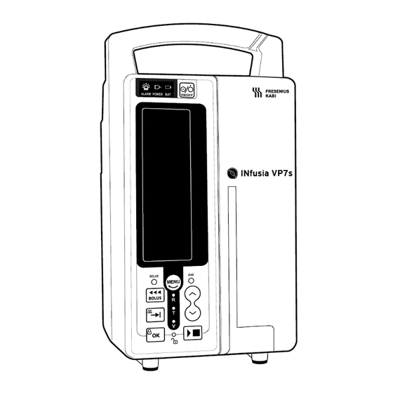
2.4 User interface 2.4.1 Front panel The front panel contains all keys and indicators (except for the door open indicator). Information: The indicators provide information about the AC power source connection, alarm priority, powered by battery, infusion modes and whether the keyboard is locked or unlocked. -
Page 13: Display
2.4.2 Display The INfusia VP7s displays the following elements on screen to indicate the pump state or infusion status. Symbol Meaning Explanation Battery Appears at the bottom left-hand corner of the screen in 3 forms, representing 3 battery operation modes as described in Section 4.2.2... -
Page 14: Drop Sensor
2.5 Drop sensor The drop sensor detects and counts the drops falling in the drip chamber, and is connected to the pump via its connection cable. Legend: 1 Drop sensor case. Contains the infrared emitter and receiver. 2 Drop indicator. This is a LED which flashes once for each drop that falls in the drip chamber. 3 Plug connector. -
Page 15: Installation
It is recommended not placing the pump higher than 1.3 meter above patient. 3.2 Installing the pump The INfusia VP7s has a pole clamp on the back for attaching it to a pole. Information: The pump is designed for installation on a pole with a diameter between 15 to 33mm. -
Page 16: Loading The Administration Set
1. Unscrew the clamp (item 1), place it around the pole (item 2), and screw the clamp until pump is fully secured to the pole. 2. Check that the pump is securely attached. Warning: Make sure the load bearing capacity of the infusion stand is more than 4 times the weight of the device. -
Page 17: Loading Procedure
3.3.2 Loading procedure Warning: Check the integrity of the administration set before use, and make sure the administration set is not connected to the patient. Prepare the solution container and administration set according to your hospital protocol. Pull the lever up Close the roller clamp as much as necessary. -
Page 18: Connecting The Drop Sensor
Warning: If the brand of the administration set is changed, or the type is changed from 20 d/mL to 60 d/mL or vice versa, the administration set must be calibrated before use. When the administration set or the bottle needs to be replaced, turn the bottle’s opening upwards to avoid overflow caused by remaining fluid in the bottle. - Page 19 1. Plug the male connector at one end of the drop sensor cable into the female connector located at the back of the pump. 2. Clamp the drop sensor onto the drip chamber. 3. Check the positioning of the drop sensor on the drip chamber and ensure that: The drip chamber is hanging vertically and the drop sensor is clamped horizontally.
-
Page 20: Operations
Warning: Connect the pump to the AC power source with the power cord supplied by Fresenius Kabi. This device must only be connected to a supply mains with protective earth. Position the device in a way that the AC power source remains readily accessible. -
Page 21: Operating On Battery
Do not drop, crush, puncture or put a high degree of pressure on the battery, as this can cause an internal short-circuit and result in overheating. Do not use the battery if it is suspected to have been damaged. Do not replace with a battery other than that delivered by Fresenius Kabi. -
Page 22: Battery Operating Mode
4.2.2 Battery operating mode When the pump is switched on and operates on battery, the battery symbol is displayed in one of the following 3 forms, each of which represents one of the 3 battery modes. Symbol Description Battery mode The symbol contains 3 white rectangles. -
Page 23: Basic Operations
8. Press the key to enter the menu. 9. Select “5.ADVANCE”, press the key to enter the password interface. 10. Prompt for password (0804) to enter the advanced configuration menu. Use to insert the numbers and use to switch digit. Press the key to confirm password. -
Page 24: Start Or Stop Infusion
3 minutes, the No Action alarm is activated. If the self-test fails, an error message switch on fault Code: X (X stands for an error code from 1 to 6 and 20) is displayed. Contact Fresenius Kabi immediately. Switch off Press and hold the key until the display goes black. -
Page 25: Rate Mode
Press the key to enter the menu. Select “1.Mode”, press the key to enter the mode select interface. Use key to select infusion mode, press to enter the mode. Set the parameters for the selected infusion mode. ... -
Page 26: Time Mode
2. Press the key to switch parameter setting cursor position. 3. When the cursor blinking at the rate setting. 4. Press the key to change the flow rate unit if needed. Information: When the flow rate setting is too low, you may not be able to change the unit from “mL/h”... -
Page 27: Volume Mode
The flow rate is determined by TIME and VTBI settings. 1. Press the key to enter the menu. Enter the mode select menu and select time mode. Press to enter the parameter set interface and the time mode indicator lights up. “VTBI”... -
Page 28: Dose Mode
Use the key to set the flow rate. Press the key. “VTBI” blinks. Use the key to set the value for volume to be infused. Press the key. “ACC ADJ” blinks. Press the key. Use the key to set flow accuracy value. Information: ... - Page 29 Information: Dose can range from 0.001 to 9999. Press the key. Dose unit “ng/kg/min” blinks. Use the key to set the dose unit. Information: Available dose units include: ng/kg/min, ug/kg/min, mg/kg/min, g/kg/min, U/kg/min, IU/kg/min, ng/kg/h, ug/kg/ h, mg/kg/ h, g/kg/ h, U/kg/h, IU/kg/h, ng/min, ug/min, mg/ min, g/min, U/min, IU/min, ng/h, ug/ h, mg/ h, g / h, U/h, IU/h, mL/h.
-
Page 30: Drug Mode
For some drugs, there is a default value and recommended range. If you require the list of drugs available in the drug library, please contact your Fresenius Kabi representative. The rate should be set according to the physician’s prescription. The setting of the parameters for the selected drug is performed in a similar process as in dose mode. -
Page 31: Bolus Start/Stop Function
5. Press the key to select the drug. 6. Set all other parameters for the drug selected as in dose mode. Information: The setting of the dose rate can exceed the recommended range. If this happens: The “Out of Dose Range” message is displayed and an audio tone sounds once. -
Page 32: Purge
Information: After the BOLUS function has started,the following are true: is displayed and blinking. BOLUS The BOLUS indicator lights up and blinks. A preset BOLUS flow rate is displayed instead of the normal flow rate. Release the key to stop the BOLUS function and resume the infusion. Information: ... -
Page 33: Kvo (Keep Vein Open)
Information: Purge rates: 600 mL/h (IVSET ≤ 35d/mL) 200 mL/h (IVSET > 35d/mL) Release the key to stop the purge function and return the device to the paused state. 4.4.10 KVO (Keep Vein Open) When the infused volume reaches the target volume during infusion, the normal flow rate automatically switches to KVO rate. -
Page 34: Configure Menu
If any alarm occurs (except for Low Battery), the flow rate returns to the previous setting. If bolus function is running, the flow rate returns to the previous setting when bolus ends. If the key is pressed, the flow rate returns to the previous setting. If the flow rate is adjusted and the key is not pressed within 5 seconds, the flow rate will returns to the previous setting. -
Page 35: Ivset
4 “Basic operations” for details). 4.5.3 IVSET 10 administration sets can be selected (built-in brand and user define). Enter the menu, select “2.IVSET”, press the key to enter the submenu. Select the administration set want to use. Press the key to save. - Page 36 Select “1.OCCL” and press the key enter submenu. Use the key to select the occlusion alarm pressure level (H, M or L) as required and press the key to save. Information: The factory default setting for the Occlusion alarm pressure level is M. ...
-
Page 37: Advance
4.5.6 Advance Enter the menu and select “5.ADVANCE”, press the key to enter the password interface. Prompt for password (0804) to enter the advanced configure menu. Use key to insert the numbers and use to switch digit. Press the key to confirm password. -
Page 38: About (Software Version Check)
If it is necessary to export logs, please contact Fresenius Kabi for data support. Enter the menu and select the“6.HISTORY”, press the key enter submenu. - Page 39 Warning: Contact Fresenius Kabi if the reset does not work and the device continues to malfunction.
-
Page 40: Cleaning And Disinfecting
5 Cleaning and disinfecting The device must be cleaned after each use, and before maintenance. Only disinfect the device after it has been cleaned, and only when appropriate. Recommended agent for cleaning: locally available multi-enzymatic cleanser or detergent (for example, Endozime by Ruhof Corporation). Recommended agent for disinfecting: 10% household bleach in water (produces 0.55% Sodium Hypochlorite). -
Page 41: Alarms
6 Alarms INfusia VP7s Infusion Pump immediately activates audible and visual alarm signals when an alarm condition occur. Warning: When an alarm is activated, check and respond to the cause of the alarm, clear the alarm. Restart the device only after the corrective action has been taken. -
Page 42: Alarm Conditions And Corrective Actions
LOW BATTERY Low Battery Yellow (blinking) Information: The device stops infusion and triggers audio and video alarm signals when a high priority alarm occurs (Excluding Infusion Complete). The device automatically enters KVO mode when the Infusion Complete alarm is activated. -
Page 43: Intelligent Alarm System
Information: In addition to the actions suggested above, see Chapter 7 “Troubleshooting” for more troubleshooting solutions. For the Battery Empty alarm, if the power loss is less than or equal to 30 seconds, the alarm settings prior to the power loss are restored automatically. ... -
Page 44: Alarm Silence
Alarm indicator lights up in red. 10 tones, repeat. Cycle: 3s Cycle: 500ms. High The alarm message is displayed. Alarm indicator lights up in yellow. 3 tones, repeat. Cycle: 5s Cycle: 2s. Middle ... -
Page 45: Alarm Signal Sound Pressure Level
In a particular set of audible alarm signals, high priority signals convey a higher level of urgency than low priority and information signals. Similarly, medium priority signals convey a higher level of urgency than low priority and information signals. 6.8 Alarm Signal sound pressure level High Priority High volume level: 78.3-80.5dB... -
Page 46: Troubleshooting
7 Troubleshooting Information: Some entries in the Troubleshooting Guide and Error Messages may involve technical details for service technicians. 7.1 Troubleshooting guide Trouble Possible causes Corrective actions Connect device to AC Battery is empty. power source. Battery connection wire is badly Check battery connection connected. - Page 47 SA/SY board is short. Replace SA/SY board. Corrective actions Possible causes include 4-18 above. include 4-18 above. Reconnect AC power AC power source is badly connected, The device cannot be switched source, or replace and battery is empty. on when the AC power source appliance inlet.
- Page 48 Live line and null line are not Check live line and null connected. line connections. Reconnect AC power AC power source is badly connected. source. Fuses are burnt out. Replace fuses. Reconnect AC power AC power source is badly connected. source.
-
Page 49: Error Messages
when the device is switched on. Door sensor (reed switch) is Replace reed switch. defective. Reinstall the magnet on Magnet falls off the device door. the door. Administration set is not installed Reinstall administration properly. set. Air-in-Line alarm is activated, Replace air detection Air detection board is defective. - Page 50 EEPROM Error error. 2. If not OK, replace the 1. EEPROM chip is defective. main board. 2. Main board is defective. 1. Check connection of Audio module self-test error speaker, and reconnect 1. Audio driver circuit is the connector if it is defective.
- Page 51 Main MCU Error or No power 1. Replace the main Red alarm light Error board. blinks and buzzer 1. Main board is defective. 2. Connect the AC cord sounds 2. AC power and battery and check the battery fail simultaneously status.
- Page 52 Battery low alarm. BATTERY/ 1. Refer to Section 6.2 1. Refer to Section 6.2 for for corrective actions. (blinking) possible causes. Warning: If the above troubleshooting measures do not guide you to solve the problem, please contact Fresenius Kabi immediately.
-
Page 53: Technical Information
8 Technical Information 8.1 Performance 8.1.1 Infusion flow rate Range: 1.0 to 1200 mL/h, or 1 to 400 d/min, Increments: 0.1 mL/h (from 1.0 to 99.9 mL/h) 1 mL/h (from 100 to 1200 mL/h) or 1 d/min Accuracy: ± 5% total accuracy over a period of 24h with a maximum infusion of 1 liter in accordance with EN/IEC 60601-2-24 Warning: Flow rate accuracy can be influenced by administration set configuration, fluid... -
Page 54: Occlusion Alarm Pressure Level
8.1.8 Occlusion alarm pressure level High (H): ≤150 kPa Medium (M): ≤100 kPa Low (L): ≤60 kPa 8.1.9 Occlusion alarm response time Flow Rate Occlusion alarm pressure level Alarm response time High ≤3h 1 mL/h ≤2h High ≤5min 25 mL/h ≤5min Information: ... -
Page 55: Technical Characteristics
8.2 Technical characteristics 8.2.1 Operation mode The pump is designed for continuously delivery of intravenous infusion. 8.2.2 Power supply specifications The wall plug must be connected directly to the mains power socket. Power source 100V - 240V, 50/60Hz, earthed Fuses F2AL/250V AC Power Maximum consumption... -
Page 56: Start-Up And Trumpet Curves
Infusion flow rate. 8.3.1 Start-up curves The following graphs are obtained from tests performed with a system consisting of an Infusia VP7s infusion pump and a VS10 set. The fluid used in the test is 0.9% saline. Flow rate: 25 mL/h... -
Page 57: Trumpet Curves
8.3.2 Trumpet curves Flow rate: 25 mL/h, the second hour Flow rate: 25 mL/h, the last hour Flow rate: 1mL/h, the second hour... - Page 58 Flow rate: 1 mL/h, the last hour...
-
Page 59: Emc Declaration
Guidance and manufacturer´s declaration – electromagnetic immunity The INfusia VP7s Infusion Pump is intended for use in the electromagnetic environment specified below. The customer or the user of the INfusia VP7s Infusion Pump should assure that it is used in such an environment. Compliance... -
Page 60: Guidance And Manufacturer´s Declaration - Electromagnetic Immunity - For Life-Supporting Me Equipment And Me Systems
Guidance and manufacturer´s declaration – electromagnetic immunity The INfusia VP7s Infusion Pump is intended for use in the electromagnetic environment specified below. The customer or the user of the INfusia VP7s Infusion Pump should assure that it is used in such an environment. Compliance... - Page 61 Portable and mobile RF communications equipment should be used no closer to any part of the INfusia VP7s Infusion Pump, including cables, than the recommended separation distance calculated from the equation applicable to the frequency of the transmitter. Recommended separation distance √...
-
Page 62: Recommended Separation Distances Between Portable And Mobile Rf Communications Equipment And The Equipment Or System -For Life-Supporting Me Equipment And Me Systems
If the measured field strength in the location in which the INfusia VP7s Infusion Pump is used exceeds the applicable RF compliance level above, the INfusia VP7s Infusion Pump should be observed to verify normal operation. If abnormal performance is observed, additional measures may be necessary, such as reorienting or relocating the INfusia VP7s Infusion Pump. -
Page 63: Device Storage And Transport
10 Device Storage and Transport If the device is not used for an extended period of time, it is recommended that the device be stored in an area that is clean, organized and compliant with the storage conditions below. 10.1 Storage and transport conditions Warning: Please store or transport the device according to the specified transport and storage conditions. -
Page 64: Services
11 Services 11.1 Maintenance Warning: Maintenance procedures are intended to be performed only by qualified personnel. It is recommended that preventive maintenance is carried out every one year. Information: If PCB diagrams, intervention procedures, test procedures, spare parts lists, and other technical information are needed for maintenance, please contact Fresenius Kabi. -
Page 65: Battery
It is necessary to recharge the battery if the device is stored for more than one month. Please contact Fresenius Kabi for a replacement battery. The old battery should be handled according to local laws. -
Page 66: Device Service Life
11.2 Warranty 11.2.1 General warranty conditions Fresenius Kabi guarantees that this product is free from defects in material and workmanship during the period defined by the accepted sales conditions, except for batteries and accessories. 11.2.2 Limited warranty... -
Page 67: Glossary Of Terms
12 Glossary of Terms Term Description Ampere Alternating Current ACC ADJ Accuracy Adjustment Cal.Vol Calibrate Solution Volume °C Degrees Celsius CISPR Special International Committee on Radio Interference Direct Current d/min Drops/min d/mL Drops/ mL EEPROM Electrically Erasable Programmable Read-Only Memory Error °F Degrees Fahrenheit... - Page 68 Volts Ampere Volts Direct Current VTBI Volume to Be Infused Watt Made in France Revision Date: May 2018 Fresenius Kabi Infusion Pump INfusia VP7s EC Representative: Fresenius Kabi Jianyuan (Changsha) Medical Fresenius Vial S.A.S. Technology Co., Ltd. Address: Address: Building 1, No. 41, Yannong Road, Oufuan Le Grand Chemin, 38590 Brézins,...
- Page 70 11212-3_master_ifu_INfusia_VP7s_ENG_MIF...
Need help?
Do you have a question about the INfusia VP7s and is the answer not in the manual?
Questions and answers