Table of Contents
Advertisement
Quick Links
Advertisement
Table of Contents

Related Manuals for Fresenius Kabi APPLIX SMART


Summary of Contents for Fresenius Kabi APPLIX SMART
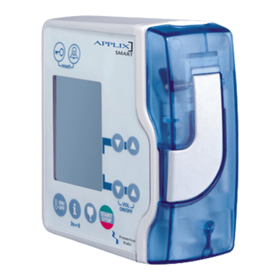
- Page 1 APPLIX Smart Enteral Feeding Pump Enteral Feeding Pump TECHNICAL MANUAL...
- Page 2 Revisions table TM APPLIX SMART INT ref TM 1722 Valid for pumps whose serial number is from 17670295 till... Date Revision Chapter Description - Precautions to be taken for flow rate test were added. - Spelling corrections. - Update of electrical characteristics, conformity to standard, maintenance (only Index "g"...
-
Page 3: Table Of Contents
1 Introduction ...................... 5 1.1 Operation diagram ................. 5 1.2 Precautions for use................6 1.3 Safety features..................6 1.4 Technical data ..................6 1.4.1 Electrical........................6 1.4.2 Mechanical ......................... 6 1.4.3 Conformity to standards ..................... 6 1.4.4 Material characteristics ....................7 1.4.5 Essential performances.................... - Page 4 4.3.20 Electrical safety test ....................29 4.3.21 Quality Control Certificate ..................31 4.4 Flow rate control .................. 33 4.4.1 Measurement with scale ..................33 4.4.2 Measurement using a test tube ................35 4.5 Cleaning and desinfecting ..............37 4.6 Storage....................38 5 Diagnosis......................39 5.1 Troubleshooting...................
-
Page 5: Introduction
1 Introduction The APPLIX Smart is intended exclusively for enteral feeding. The APPLIX Smart pump is a peristaltic pump delivering enteral nutrition and hydration to the patient through a feeding tube. It can be used with both home patients and hospital patients. -
Page 6: Precautions For Use
1.2 Precautions for use The manufacturer may in no case be held responsible for any medical or any other problem, resulting from a mis-use of the equipment. Consult the Instructions For Use for further information. Temperature: +13°C to +40°C. ... -
Page 7: Material Characteristics
Pole clamp holder PA + aromatic 1.4.5 Essential performances Applix Smart essential performances are defined as follows in standard operating conditions: Flow rate accuracy: +/-10% at 300 mL/h, with medical water. Downstream occlusion time: less than 2 min. at 150 mL/h, with medical water at 21°C. - Page 8 applix01_01h_int.fm...
-
Page 9: Description And Operation
Pump door Door lever Holder The APPLIX Smart is composed of a pump which can be mounted on a holder. 2.1.1 The pump The APPLIX Smart is composed of a top surface unit holding the mechanical and electronic assembly. A housing fastened on the top surface unit performs mechanical protection and waterproofness of the pump. - Page 10 The housing is holding: A keyboard. Five contacts to connect the pump to the holder. The housing is connected to the different parts by means of connectors and contacts. Keyboard connector Contacts holder/pump to CPU board to CPU board 5 4 3 2 1 Keyboard connector to CPU board Description...
- Page 11 The top surface unit is composed of: A CPU board. A pumping unit. A top surface. The CPU board The CPU board is holding the power and command electronics for the pump and the LCD screen required for man/machine interface. Optical Motor detection...
- Page 12 Connector J5 to battery Description Battery (0 V) CTN GND CTN (+) + V Bat Connector J6 to holder contacts Description Alarm command ouput (nurse call) Output (Txd) Input (Rxd) Power supply Connector J16 to motor Description Motor - Motor + Connector J17 to air detection Description Transmitter (+) anode...
-
Page 13: The Holder
2.1.2 The holder The holder is composed of a housing equipped with a clamp used to fasten it on a pole. The holder includes a supply board which supplies 7.75 VDC mains to the APPLIX pump. It also performs the loading of the battery included in the pump. It is also equipped with: ... - Page 14 RS232 connection Characteristics: Plug: 8-pin male RJ45. Length of cable: 2.5 m. Cable: ref. MJ8 P8C SUNS-PUlow vlt computer. External connection: DB9 female. Connection Pin RJ45 DB9 female 3 TxD 7 RTS 4 DTR 2 RxD 5 GND Plug male RJ45.
-
Page 15: Functional Description
2.2 Functional description The APPLIX pump is composed of three functional subassemblies: A subassembly of holding and control of giving set. A pumping subassembly. A holder subassembly with external connections. 2.2.1 Subassembly of holding and control of giving set The giving set is installed on the top surface and maintained in position by the door. - Page 16 applix02_01g_int.fm...
-
Page 17: Calibration Menu
3 Calibration menu The calibration menu is used to perform tests and consult the different values of the pump. The modification of these parameters can only be performed from a PC equipped with the APPLIX control software. The software can be ordered by approved and qualified technicians who have been trained. - Page 18 applix03_01g_int.fm...
-
Page 19: Preventive Maintenance
They must be collected separately and disposed of according to local regulations. For further information pertaining to waste processing regulation, contact your local Fresenius Kabi organisation or the local distributor. applix04.1&2_01g_int.fm... - Page 20 applix04.1&2_01g_int.fm...
-
Page 21: Checks
Preventive maintenance 4.3 Checks In order to carry out a tracking of the equipment within the limits of a preventive maintenance, a quality control is recommended every 12 months (refer to the "Quality Control certificate"). Before the control procedure, perform a preliminary charging of the battery (5 hours). -
Page 22: Battery Temperature
4.3.2 Battery temperature CAL 50 The battery temperature is The value of the battery temperature is displayed in displayed in arbitrary units. arbitrary units. Check that this value complies with the range 2964 0°C < T° < 60°C. Correspondence table: Value in arbitrary units Temperature (°C) -
Page 23: Battery Voltage
4.3.3 Battery voltage CAL 51 The battery voltage is displayed in The value of the battery voltage is displayed in arbitrary arbitrary units. units. Check that this value complies with the range 1992 0 V < U < 6 V. Correspondence table: Value in arbritrary Voltage (V) -
Page 24: Buzzer Test
4.3.5 Buzzer test CAL 98 This test enables to test the buzzer Press down "START" to go from a level to another: START sound levels. STOP , no sound. , minimum level. , middle level. ... -
Page 25: Optical Background Signal
4.3.8 Optical background signal CAL 103 The optical background signal Open the door and keep empty the clamp location. which can disturb Check that this value complies with the range the sensor -1 < U < 500 . operation, is displayed in If the value is out of tolerance, calibrate the sensor (using Applix control maintenance... -
Page 26: Lcd
4.3.10 LCD CAL 108 This test enables to control the good Press "START STOP" to start the test. operation of the START STOP LCD. Check if the LCD is functioning correctly. Press down "START STOP" to leave the test and carry on ... -
Page 27: Motor Command Test
4.3.13 Motor command test CAL 119 This test enables to control the Insert a giving set. motor command. Close the door. START Press "START STOP" key to start the test. STOP Motor command ... -
Page 28: Downstream Occlusion Alarm Test
4.3.16 Downstream occlusion alarm test To perform this test, exit test mode According to the diagram below: Pocket 50 cm Applix 3 ways stopcock Manometer Container Insert a giving set, full of water, with a clamp. Connect a manometer to the giving set outlet. ... -
Page 29: Air Detection Alarm Test
4.3.18 Air detection alarm test To perform this test, exit test mode. Insert a giving set, full of water, with a clamp. Close the door, set the flow rate at 300 ml/h and press START "START STOP". STOP ... - Page 30 applix04.3_01i_int.fm...
-
Page 31: Quality Control Certificate
Preventive maintenance 4.3.21 Quality Control Certificate Use this table to note the results of the different tests. Device type: Code: Device serial: Conformity N° Procedure Obtained value Check the general aspect of the pump and of the labels. CAL50 ... - Page 32 Conformity N° Procedure Obtained value CAL119 Motor command test, Time revolution (ms) Min Time revolution (ms) Max 1600 1200 1000 Door alarm test: Presence of alarm with open door when start pumping: ***** ...... Presence of alarm at the opening of the door during pumping: ....... ...
-
Page 33: Flow Rate Control
Canula type 10 ml/h < x < 30ml/h x > 30 ml/h G18 or G21 Giving set APPLIX Smart/Vision Bag referenced 7751711. Temperature range: 22.5°C + 2.5°C Installation According to the installation drawing shown below. 50 cm... - Page 34 Make sure the horizontal installation plane is respected. Fill the container with 600 ml or more of distilled water. Connect a giving set with the container. Connect the canula with the distal end of the giving set. ...
-
Page 35: Measurement Using A Test Tube
Flow rate value Canula type 10ml/h < x < 30ml/h x > 30 ml/h G18 or G21 Giving set APPLIX Smart/Vision Bag referenced 7751711. Temperature range: 22.5°C + 2.5°C Installation According to the installation drawings shown below. 50 cm... - Page 36 Operating mode Select a flow rate at 300 ml/h. Start pumping and start the stop clock at the same time. After a time interval T stop the pump. Measure the volume that is pumped into the test tube or beaker within the time interval T of 15 min.
-
Page 37: Cleaning And Desinfecting
Preventive maintenance 4.5 Cleaning and desinfecting Clean the Applix pump and pump holder as soon as they become contaminated with tube feed or drugs. Otherwise clean once a week. Disconnect pump from the mains before cleaning. After cleaning, the unit should be left to dry for approximately 5 minutes before being started or reconnected to the mains. -
Page 38: Storage
4.6 Storage The storage of the Applix pump and pump holder must be done in a dry and cool place. The recommended storage and transport conditions are between -20°C to +45°C. Relative humidity: 85% maximum, no condensation. Atmospheric pressure: 700 hPa to 1060 hPa. Consult the Instructions For Use for further information. -
Page 39: Diagnosis
5 Diagnosis 5.1 Troubleshooting Problem Cause Action Unjustified door alarm. Door magnet is missing on the door. Replace the door and perform a calibration of the door. Wrong calibration. Re-calibrate the door position. Hall sensor is out of order. ... - Page 40 applix05.1_01g_int.fm...
-
Page 41: Error Messages
Diagnosis 5.2 Error messages Error Description Recommended action code Value of A/D-converter 0 out Check air detection (see §4 air detection of range. " "). Value of A/D-converter 1 out Check the door position (see §4 door of range. - Page 42 Error Description Recommended action code US detector for air detection Check air detection (see §4 air detection is defective. " "). Too high signal level wit- Replace the top surface. hout pulse. Signal is higher than alarm ...
- Page 43 Error Description Recommended action code Measured current too low to Change the CPU board. calculate occlusion. Check mechanical system. Measured current low to Check the mechanical system. calculate occlusion. Replace the CPU board. Rate is too high (> 600 ml/h) ...
- Page 44 applix05.2_01g_int.fm...
-
Page 45: Intervention Procedures
Warning: - Use ONLY recommended accessories and options delivered with the device. NO PART IS REPAIRABLE. When replacing components, only use Fresenius Kabi spare parts. Please refer to the "Spare parts catalogue" for ordering. - Any instrument or device used for maintenance must be regularly checked or recalibrated according to its specifications and local regulations. - Page 46 applix06.0_0001h_int.fm...
-
Page 47: N°1, Procedure: Housing
Intervention procedure N°1, Procedure: Housing Safety: For safety reasons, the technician should not carry out any maintenance when the equipment is voltage supplied. Disconnect the mains power supply cable. Required tools 1 Z1 Posidriv screwdriver. 1 flat screwdriver (small). ... - Page 48 Disassembly During interventions on electronic components, it is recommended to hold a ground- connected antistatic band and to work on an antistatic foam mat. Gently uncouple the front face/housing assembly, bending it to prevent LCD to scrape on the housing windows.
- Page 49 Maintain the Applix pump in this position and return it on the "contact" face (housing to the left). Remove the housing and take care of not tearing out the keyboard flat cable (marker 4). With a small flat screwdriver, loosen the connector (marker 5). ...
- Page 50 applix06.0_0010g_int.fm...
-
Page 51: N°2, Procedure: Rechargeable Battery
Intervention procedure N°2, Procedure: Rechargeable battery Safety: For safety reasons, the technician should not carry out any maintenance when the equipment is voltage supplied. Disconnect the mains power supply cable. Required tools 1 Z1 Posidriv screwdriver. 1 flat screwdriver (small). ... - Page 52 For environmental protection, do not throw the batteries in the housewaste. Remove the battery from the device prior to destruction and as during normal maintenance replacement, return it to a competent recycling organisation. Re-assembly Only replace with the same model of battery recommended by the manufacturer. Carry out the reverse operations of disassembly taking care of correctly positioning the keyboard flat cable and the strands.
-
Page 53: N°3, Procedure: Board
Intervention procedure N°3, Procedure: Board Safety: For safety reasons, the technician should not carry out maintenance when the device is voltage supplied. Disconnect the mains power supply cable. Required tools 1 Z1 Posidriv screwdriver. 1 flat screwdriver (small). ... - Page 54 Disconnect all the connectors from the board. Unscrew the 2 cross-pointed screws (marker 1), that connect the board with the pumping unit. Remove the board, uncliping the board (marker 2) and pulling at the clips level (marker 3). Re-assembly ...
-
Page 55: N°4, Procedure: Pumping Unit
Intervention procedure N°4, Procedure: Pumping unit Safety: For safety reasons, the technician should not carry out any maitenance when the equipment is voltage supplied. Disconnect the mains power supply cable. Required tools 1 Z1 Posidriv screwdriver. 1 flat screwdriver (small). ... - Page 56 Unscrew the 2 screws (marker 5) below. Remove the pumping unit. Re-assembly Carry out to the reverse operations of disassembly taking care of correctly positioning the keyboard flat cable and the strands. Pumping rod is in down position Care must be taken with the membrane.
-
Page 57: N°5, Procedure: Membrane
Intervention procedure N°5, Procedure: Membrane Safety: For safety reasons, the technician should not carry out maintenance when the device is voltage supplied. Disconnect the mains power supply cable. Required tools 1 Z1 Posidriv screwdriver. 1 flat screwdriver (small). ... - Page 58 Re-assembly Position the membrane (marker 3). Place the membrane clips (marker 2) above each rod (marker 1). Quickly connect, one after the other, the two clips to fix the membrane. Carry out to the reverse operations of disassembly taking care of correctly positioning the keyboard flat cable and the strands.
-
Page 59: N°6, Procedure: Gearbox/Motor
Intervention procedure N°6, Procedure: Gearbox/motor Safety: For safety reasons, the technician should not carry out any mainenance when the equipment is voltage supplied. Disconnect the mains power supply cable. Required tools 1 Z1 Posidriv screwdriver. 1 flat screwdriver (small). ... - Page 60 Re-assembly Place the gear motor engaging the belt (marker 3) carefully on the gear of the pumping assembly. Screw the 3 cross-pointed screws marker 2) ensuring the correct positioning, for each screw and the silent block as well as the captive nut. ...
-
Page 61: Spare Parts Catalogue
7 Spare parts catalogue Refer to the document entitled "Applix - Spare parts catalogue". applix08.0_001g_int.fm... - Page 62 applix08.0_001g_int.fm...
- Page 63 Modifications may be done in future editions. COPYRIGHT © 2014, Fresenius Kabi. This document may not be reproduced in part or in whole without the written permission of Fresenius Kabi. Fresenius Vial - Le Grand Chemin - 38590 Brézins (FRANCE)
Need help?
Do you have a question about the APPLIX SMART and is the answer not in the manual?
Questions and answers