Table of Contents
Advertisement
Quick Links
Installation, Operation, and Maintenance
Packaged Rooftop Air
Conditioners Foundation®
Cooling Only and Electric Heat
3 to 5 Tons, 60 Hz
Model Number: EDK036-060
Only qualified personnel should install and service the equipment. The installation, starting up, and servicing of heating, ventilating, and air-conditioning equipment
can be hazardous and requires specific knowledge and training. Improperly installed, adjusted or altered equipment by an unqualified person could result in death or
serious injury. When working on the equipment, observe all precautions in the literature and on the tags, stickers, and labels that are attached to the equipment.
July 2024
SAFETY WARNING
RT-SVX078A-EN
Advertisement
Table of Contents

Subscribe to Our Youtube Channel
Related Manuals for Trane Foundation EDK036-060


Summary of Contents for Trane Foundation EDK036-060
- Page 1 Installation, Operation, and Maintenance Packaged Rooftop Air Conditioners Foundation® Cooling Only and Electric Heat 3 to 5 Tons, 60 Hz Model Number: EDK036-060 SAFETY WARNING Only qualified personnel should install and service the equipment. The installation, starting up, and servicing of heating, ventilating, and air-conditioning equipment can be hazardous and requires specific knowledge and training.
- Page 2 (HCFCs). Not all refrigerants containing these compounds bump cap, fall protection, electrical PPE and arc have the same potential impact to the environment. Trane flash clothing). ALWAYS refer to appropriate advocates the responsible handling of all refrigerants.
- Page 3 Non-Trane personnel should always follow local regulations. This document and the information in it are the property of Trane, and may not be used or reproduced in whole or in part without written permission. Trane reserves the right to WARNING...
-
Page 4: Table Of Contents
Table of Contents Model Number Description ....6 Main Unit Power ......22 Standard Wiring . - Page 5 Table of Contents Unit Economizer Control (ECA) ... . . 35 For Commercial Unitary Equipment Rated Error Code ......35 25 Tons and Under and Related Accessories.
-
Page 6: Model Number Description
Model Number Description Digit 1 — Unit Function Digit 11 — Minor Design Sequence Digit 17 — Coil Protection E = DX Cooling A = Rev A 0 = Standard Coil 4 = CompleteCoat™ Condenser Coil Digit 2 — Cooling Efficiency Digit 12, 13 —... -
Page 7: General Information
General Information WARNING • Inspect the complete exterior for signs of shipping damages to unit or packing material. Fiberglass Wool! • Verify that the nameplate data matches the sales order Exposure to glass wool fibers without all necessary and bill of lading. PPE equipment could result in cancer, respiratory, •... -
Page 8: Economizer Control Actuator Electromechanical Control
General Information Economizer Control Actuator compressor contactor coil is connected to the ‘CC’ terminal of the LSD. If the high pressure control switch or the Electromechanical Control discharge line thermostat is open, the 24 Vac signal to the The ECA monitors the mixed air temperature, return air SI input of the LSD is interrupted and the compressor temperature, minimum position setpoint (local or remote), contactor coil supply is disabled by the LSD. -
Page 9: Initiation Of Operating Modes - Jade
General Information Sensor sensor must utilize a normally open contact for proper operation. This optional sensor can be added for Demand Control Ventilation (DCV) functionality. On units with a low leak If an occupancy sensor is not used, another option to economizer, configure the JADE controller by setting the controlling occupied and unoccupied status is to use the G following parameters:... -
Page 10: Dimensional Data
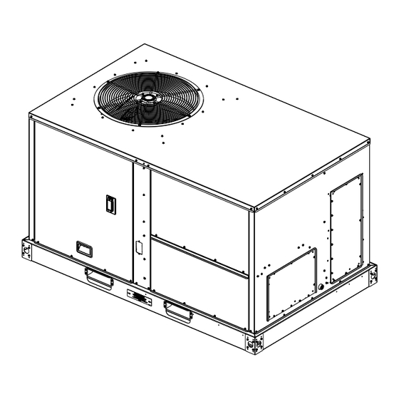
Dimensional Data Below figure illustrates the minimum operating and service Providing less than the recommended clearances may clearances for either a single or multiple unit installation. result in condenser coil starvation, short-circuiting of These clearances are the minimum distances necessary to exhaust and economizer airflows, or recirculation of hot assure adequate serviceability, cataloged unit capacity, and condenser air. - Page 11 Dimensional Data Figure 2. Cooling with optional electrical heat — overview (electric/electric) DISCONNECT SWITCH ACCESS CONDENSATE DRAIN CONNECTION Figure 3. Cooling with optional electrical heat — front and side views (electric/electric) 42.004” 42.558” 20.735” 15.860” 7.860” 42.175” 43.675” 44.675” 76.814” 47.934”...
- Page 12 Dimensional Data Figure 4. Cooling with optional electrical heat and electric/electric units — bottom view RETURN 25-5/8” 5-19/32” 7-1/32” 10-7/8” 17-3/4” 27-1/8” 19-3/8” 17-3/8” 15-3/8” 12-27/32” 6-25/32” 12-1/8” 5-19/32” 25-1/8” 20-11/16” SUPPLY Figure 5. Cooling with optional electrical heat and electric/electric units — back view (horizontal configuration) RETURN SUPPLY 25.125”...
- Page 13 Dimensional Data Figure 6. Cooling with optional electrical heat and electric/electric units — roof curb 14.000” 70.875” 3.000” 21.060” 41.990” 15.188” SUPPLY 3.000” 14.430” 36.938” 32.188” 3.548” RETURN 14.000” 1.500” 41.986” 70.871” Figure 7. Cooling with optional electrical heat and electric/electric units — downflow unit clearance CLEARANCE 68”...
- Page 14 Dimensional Data Figure 8. Cooling with optional electrical heat and electric/electric units — barometric relief and economizer ECONOMIZER BAROMETRIC RELIEF 42” BAROMETRIC RELIEF 11-29/32” 7-31/32” 7-27/32” 13-13/32” 14-5/8” 4-1/8” 3-9/32” 32-5/32” 47-15/16” 76-13/16” RIGHT VIEW OF UNIT BACK VIEW OF UNIT Figure 9.
-
Page 15: Weights
Weights Table 1. Maximum unit and corner weights (lb) and center of gravity dimensions (in.) cooling with optional electric heat (electric/electric) units only Weights (lb) Corner Weights Center of Gravity (in.) Tons Unit Model No. Shipping Length Width EDK036* EDK048* EDK060* Weights are approximate. -
Page 16: A2L Information
• To be repaired only by trained service At all times, Trane’s maintenance and service guidelines personnel. shall be followed. In in doubt, contact Trane technical support for assistance. • Do not puncture refrigerant tubing. All maintenance staff and others working in the local area •... -
Page 17: Leak Detection
Verify continuity of earth bonding. The recovery equipment shall be in good working order • Replace electrical components with Trane replacement with instructions available. Equipment shall be suitable for parts, or those meeting the same ratings and qualified the recovery of the flammable refrigerant. For specific for flame arrest protection, UL LZGH2 category. -
Page 18: Decommissioning
A2L Information • Ensure that the refrigerating system is earthed prior to the equipment are removed from site promptly and all charging the system with refrigerant. isolation valves on the equipment are closed off. • Label the system when charging is complete (if not 11. -
Page 19: Minimum Room Area Limits
A2L Information installed accessory electric heaters, gas heaters, relays, system. A ducted system requires circulation airflow and contactors) were evaluated during product UL listing. unless the smallest room it serves is larger than the adjusted A threshold. This product contains a leak Minimum Room Area Limits detection system if a circuit charge is greater than 3.91 lbs. -
Page 20: Leak Detection System
ANSI\ASHRAE Standard 15-2022, Section 7.6.4. or is disconnected, the unit will initiate the mitigation actions. Mitigation actions may be verified by disconnecting the sensor. The refrigerant sensors do not need service. Use only Trane-approved sensors when replacement is required. RT-SVX078A-EN... -
Page 21: Installation
Installation Unit Foundation If a Curb Accessory Kit is not used: 1. The ductwork can be attached directly to the factory- WARNING provided flanges around the unit’s supply and return air Risk of Roof Collapsing! openings. Be sure to use flexible duct connections at the unit. -
Page 22: Factory Installed Economizer
Installation Factory Installed Economizer A condensate drain line must be connected to the P-Trap. Pitch the drain lines at least 0.5-inch for every 10 feet of • Confirm the economizer is pulled out into the operating horizontal run to assure proper condensate flow. Do not position. -
Page 23: Standard Wiring
Installation Standard Wiring Figure 12. Through the base electrical option The electrical service must be protected from over current and short circuit conditions in accordance with NEC requirements. Protection devices must be sized according to the electrical data on the nameplate. •... -
Page 24: Voltage Imbalance
Installation Note: Resistance in excess of 3 ohms per conductor 4. Do not run the AC low voltage wiring in the same could cause component failure due to insufficient conduit with the high voltage power wiring. AC voltage supply. 5. Route low voltage wiring as per Figure 13, p. -
Page 25: Compressor Crankcase Heaters
Installation side of the optional factory mounted disconnect switch Before starting the unit in the Cooling mode, set the to the Off position. system switch to the Off position and turn the main power disconnect to the On position and allow the crankcase 2. -
Page 26: Factory-Mounted Unit Options
Installation Factory-Mounted Unit Options 2. If the conduit required for your application is larger than 1 1/2–in., remove the termination plate and connect to Unit Disconnect (FIYUDC) the larger hole using field supplied reducing washers. 3. Route the power wires and ground conductor through WARNING conduit and into the bottom of the factory installed Hazardous Voltage and Equipment... -
Page 27: Pre Start
Pre Start Verifying Proper Airflow (Units Fan Test and Minimum Ventilation. Connect red thermostat wire (R) to black thermostat wire (G). with Belt Drive Indoor Fan) Economizer Cooling. Connect a jumper wire across OAT Much of the systems performance and reliability is closely on Economizer Control (ECA). -
Page 28: Start-Up
To Perform Checkout Tests: Note: Copeland YA scroll compressors for R-454B units use Trane OIL00094. 1. Scroll to the desired test in the checkout menu using buttons. Table 5. Compressor types 2. Press the button to select the item. -
Page 29: Heating Start-Up
Start-Up Final System Set Up 4. Repeat Step 1 through Step 3 for each refrigerant circuit. After completing all of the pre-start and startup procedures 5. To stop the SERVICE TEST, turn the main power outlined in the previous sections (i.e., operating the unit in disconnect switch to the Off position or proceed to the each of its modes through all available stages of cooling next component start-up procedure. -
Page 30: Maintenance
Maintenance Make sure all personnel are standing clear of the unit 3. Set the small O-ring at zero on the force scale of the before proceeding. The system components will start when gauge plunger. the power is applied. 4. Place the large end of the gauge at the center of the belt span;... -
Page 31: Monthly Maintenance
Maintenance Monthly Maintenance NOTICE Equipment Damage! Before completing the following checks, turn the unit OFF and lock the main power disconnect switch open. Forcibly turning the motor shaft can damage the gear train and motor beyond repair. WARNING Never turn the motor shaft by hand or with a Hazardous Voltage! wrench. -
Page 32: Coil Cleaning
Maintenance Coil Cleaning Microchannel (MCHE) Coils Regular coil maintenance, including annual cleaning NOTICE enhances the unit’s operating efficiency by minimizing the Coil Damage! following: Failure to follow instructions below could result in • Compressor head pressure and amperage draw coil damage. •... - Page 33 Maintenance RT-SVX078A-EN...
-
Page 34: Troubleshooting
Troubleshooting WARNING Note: You can also navigate to the Alarms menu at any time. Hazardous Service Procedures! 2. Once the alarm has been identified and the cause has Failure to follow all precautions in this manual and on been removed (for example, replaced faulty sensor), the tags, stickers, and labels could result in death or the alarm can be cleared from the display. -
Page 35: Resetting Cooling And Heating
Troubleshooting Table 10. FDD troubleshooting Faults Damper not Air temp. sensor Not economizing Economizing when it Excess outdoor Tests modulating failure/fault when it should should not Damper Stuck Open Damper Stuck at Minimum Bad or Unplugged Actuator Sensor Hard Failure Actuator Mechanically Disconnected Resetting Cooling and Heating... -
Page 36: Wiring Diagrams
Wiring Diagrams Note: Wiring diagrams can be accessed via e-Library by number search field or by contacting technical entering the diagram number in the literature order support. Table 11. Wiring diagrams Type of Airflow Schematic Type Voltage Diagram Number Description Cooling only or Electric Heat Power 208–575... -
Page 37: Warranty
Under and Related Accessories warehouse at the warrantor-designated shipping point, freight allowed to Buyer’s city (or port of export for Products Covered — This warranty is extended by Trane, shipments outside the conterminous United States) a and applies to the following products: replacement product or, at the option of the warrantor, parts •... - Page 38 Notes RT-SVX078A-EN...
- Page 39 Notes RT-SVX078A-EN...
- Page 40 For more information, please visit trane.com or americanstandardair.com. Trane and American Standard have a policy of continuous product and product data improvement and reserve the right to change design and specifications without notice. We are committed to using environmentally conscious print practices.
Need help?
Do you have a question about the Foundation EDK036-060 and is the answer not in the manual?
Questions and answers