Table of Contents
Advertisement
Installation, Operation, and Maintenance
Packaged Rooftop Air
Conditioners Foundation™ ™
Cooling Only and Electric Heat
3 to 5 Tons, 60Hz
Model Numbers: EBC036-060
Only qualified personnel should install and service the equipment. The installation, starting up, and servicing of heating, ventilating, and air-conditioning
equipment can be hazardous and requires specific knowledge and training. Improperly installed, adjusted or altered equipment by an unqualified person
could result in death or serious injury. When working on the equipment, observe all precautions in the literature and on the tags, stickers, and labels that
are attached to the equipment.
April 2022
S S A A F F E E T T Y Y W W A A R R N N I I N N G G
R R T T - - S S V V X X 0 0 5 5 7 7 F F - - E E N N
Advertisement
Table of Contents

Related Manuals for Trane EB 036 Series


Summary of Contents for Trane EB 036 Series
- Page 1 Installation, Operation, and Maintenance Packaged Rooftop Air Conditioners Foundation™ ™ Cooling Only and Electric Heat 3 to 5 Tons, 60Hz Model Numbers: EBC036-060 S S A A F F E E T T Y Y W W A A R R N N I I N N G G Only qualified personnel should install and service the equipment.
- Page 2 A A L L W W A A Y Y S S r r e e f f e e r r t t o o a a p p p p r r o o p p r r i i a a t t e e S S a a f f e e t t y y D D a a t t a a impact to the environment. Trane advocates the...
- Page 3 N N o o n n - - T T r r a a n n e e p p e e r r s s o o n n n n e e l l s s h h o o u u l l d d a a l l w w a a y y s s f f o o l l l l o o w w property of Trane, and may not be used or reproduced l l o o c c a a l l r r e e g g u u l l a a t t i i o o n n s s .
-
Page 4: Table Of Contents
Table of Contents Model Number Description ....5 Unit Disconnect (FIYUDC)... . . 21 General Information . -
Page 5: Model Number Description
Model Number Description Digit 1 — Unit Type Digit 10 — Heating Capacity Digit 15 — Supply Fan/Drive Type/ Motor E = Packaged Cooling, Electric Heat 0 = No Heat 0 = Standard Motor A = 5 kW Electric Heat 1 = Oversized Motor B = 7.5 kW Electric Heat Digit 2 —... -
Page 6: General Information
General Information W W A A R R N N I I N N G G I I m m p p o o r r t t a a n n t t : : Do not proceed with installation of a damaged unit without sales F F i i b b e e r r g g l l a a s s s s W W o o o o l l ! ! representative’s approval. -
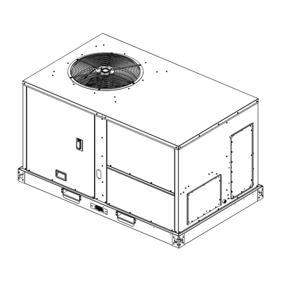
Page 7: Unit Description
G G e e n n e e r r a a l l I I n n f f o o r r m m a a t t i i o o n n Unit Description and phase unbalance. It is intended to protect compressors from reverse rotation. -
Page 8: Initiation Of Operating Modes - Jade
G G e e n n e e r r a a l l I I n n f f o o r r m m a a t t i i o o n n Occupancy Sensor The supply air duct sensor (X1310004002) is set to open at 240°F. -
Page 9: Dimensional Data
Dimensional Data Below figure illustrates the minimum operating and Providing less than the recommended clearances may service clearances for either a single or multiple unit result in condenser coil starvation, “short-circuiting” of installation. These clearances are the minimum exhaust and economizer airflows, or recirculation of distances necessary to assure adequate serviceability, hot condenser air. - Page 10 D D i i m m e e n n s s i i o o n n a a l l D D a a t t a a Figure 2. Cooling with optional electrical heat — overview (electric/electric) DISCONNECT SWITCH ACCESS CONDENSATE DRAIN CONNECTION Figure 3.
- Page 11 D D i i m m e e n n s s i i o o n n a a l l D D a a t t a a Figure 4. Cooling with optional electrical heat and electric/electric units —bottom view RETURN 25-5/8”...
- Page 12 D D i i m m e e n n s s i i o o n n a a l l D D a a t t a a Figure 6. Cooling with optional electrical heat and electric/electric units — roof curb 14.000”...
- Page 13 D D i i m m e e n n s s i i o o n n a a l l D D a a t t a a Figure 8. Cooling with optional electrical heat and electric/electric units — barometric relief and economizer ECONOMIZER BAROMETRIC RELIEF 42”...
-
Page 14: Weights
Weights Table 1. Maximum unit and corner weights (lb) and center of gravity dimensions (in.) cooling with optional electric heat (Electric/Electric) units only Weights (lb) Corner Weights Center of Gravity (in.) Unit Model Tons Shipping Length Width EBC036* EBC048* EBC060* Weights are approximate. - Page 15 W W e e i i g g h h t t s s Figure 11. Rigging and center of gravity data CENTER OF GRAVITY WIDTH CENTER OF GRAVITY LENGTH RT-SVX057F-EN...
-
Page 16: Installation
Installation Unit Foundation operating sounds from transmitting through the ductwork. W W A A R R N N I I N N G G All outdoor ductwork between the unit and the R R i i s s k k o o f f R R o o o o f f C C o o l l l l a a p p s s i i n n g g ! ! structure should be weather proofed after installation is completed. -
Page 17: Factory Installed Economizer
I I n n s s t t a a l l l l a a t t i i o o n n ☐ Rigging the unit. N N o o t t e e : : Use 1-inch PVC pipe to connect to the drain pan outlet provided in the unit. -
Page 18: Main Unit Power
I I n n s s t t a a l l l l a a t t i i o o n n Main Unit Power Figure 12. Through the base electrical option W W A A R R N N I I N N G G P P r r o o p p e e r r F F i i e e l l d d W W i i r r i i n n g g a a n n d d G G r r o o u u n n d d i i n n g g R R e e q q u u i i r r e e d d ! ! F F a a i i l l u u r r e e t t o o f f o o l l l l o o w w c c o o d d e e c c o o u u l l d d r r e e s s u u l l t t i i n n d d e e a a t t h h o o r r... -
Page 19: Voltage Imbalance
I I n n s s t t a a l l l l a a t t i i o o n n controls and the unit’s termination point does not 3. Be sure to check all loads and conductors for exceed three (3) ohms/conductor for the length of grounds, shorts, and mis-wiring. -
Page 20: Electrical Phasing
I I n n s s t t a a l l l l a a t t i i o o n n • VD = Line Voltage reading that deviates the farthest 3. Close the field supplied main power disconnect from the average voltage. -
Page 21: Checklist
I I n n s s t t a a l l l l a a t t i i o o n n Close the main power disconnect switch and the unit W W A A R R N N I I N N G G mounted disconnect switch, if applicable. - Page 22 I I n n s s t t a a l l l l a a t t i i o o n n Figure 14. Field wiring routing - factory installed disconnect switch RT-SVX057F-EN...
-
Page 23: Pre Start
Pre Start Verifying Proper Air Flow (Units F F a a n n T T e e s s t t a a n n d d M M i i n n i i m m u u m m V V e e n n t t i i l l a a t t i i o o n n . . Connect red thermostat wire (R) to black thermostat wire (G). -
Page 24: Start Up
(Menu Up) to end the test (e.g. turn off the relay). than this will result in compressor damage. N N o o t t e e : : Copeland SXA scroll compressors for R410A units use Trane OIL00094. Compressor types and appropriate oil charge is listed in the following tables. -
Page 25: Heating Start-Up
S S t t a a r r t t U U p p Table 3. Compressor types 2. Verify that the heater stage is operating properly. 3. Clamp an amp meter around one of 2 stage Tonnage Compressor 1 heater power wires at the heater contactor (if EB*036 SXA031... -
Page 26: Maintenance
Maintenance Make sure all personnel are standing clear of the unit deflection value determined in Step before proceeding. The system components will start 3. Set the small O-ring at zero on the force scale of the when the power is applied. gauge plunger. -
Page 27: Monthly Maintenance
M M a a i i n n t t e e n n a a n n c c e e Table 5. Belt tension measurement and deflection ranges (in./lb.) Deflection Force (lb) Smallest Sheave Belts Cross Super Gripbelts and Unnotched Gripnotch Belts and Diameter Range RPM Range... -
Page 28: Heating Season
M M a a i i n n t t e e n n a a n n c c e e ☐ Make sure that all retaining screws are reinstalled in W W A A R R N N I I N N G G the unit access panels once these checks are H H a a z z a a r r d d o o u u s s C C h h e e m m i i c c a a l l s s ! ! complete. - Page 29 M M a a i i n n t t e e n n a a n n c c e e Table 6. Unit data log Complete Unit Model Number Unit Serial Number Wiring Diagram Numbers (from unit control panel) -schematic(s) -connections Network ID...
- Page 30 M M a a i i n n t t e e n n a a n n c c e e RT-SVX057F-EN...
-
Page 31: Troubleshooting
Troubleshooting W W A A R R N N I I N N G G alarms. N N o o t t e e : : Note: You can also navigate to the Alarms H H a a z z a a r r d d o o u u s s S S e e r r v v i i c c e e P P r r o o c c e e d d u u r r e e s s ! ! menu at any time. -
Page 32: Resetting Cooling And Heating
T T r r o o u u b b l l e e s s h h o o o o t t i i n n g g Table 8. FDD troubleshooting FAULTS Air temp. sensor Damper not Not economizing Economizing when Excess... -
Page 33: Wiring Diagrams
Wiring Diagrams N N o o t t e e : : Wiring diagrams can be accessed via e-Library order number search field or by contacting by entering the diagram number in the literature technical support. Table 9. Wiring diagrams Type of Airflow Schematic Type Voltage... -
Page 34: Warranty
• All accessories for the above products which are fired heat exchanger which has been repaired or sold by Trane and applied in accordance with Trane altered in such manner as, in the judgement of the specifications. warrantor, affects its stability or reliability. This... - Page 35 N N o o t t e e s s RT-SVX057F-EN...
- Page 36 For more information, please visit trane. com or americanstandardair.com. Trane and American Standard have a policy of continuous product and product data improvement and reserve the right to change design and specifications without notice. We are committed to using environmentally conscious print practices.
Need help?
Do you have a question about the EB 036 Series and is the answer not in the manual?
Questions and answers