Advertisement
Quick Links
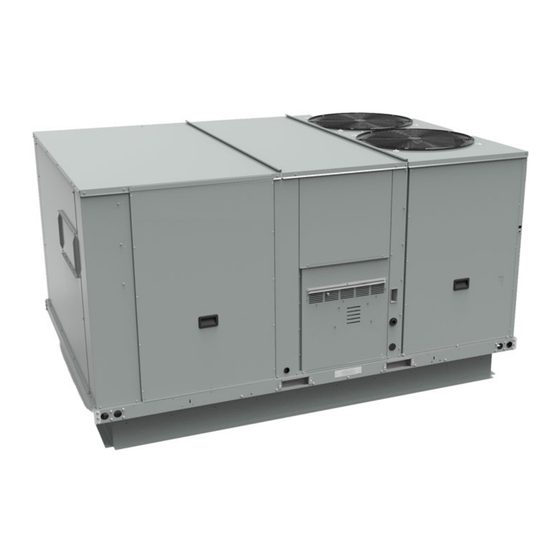
Installation, Operation, and Maintenance
Foundation™ Packaged Rooftop
Units
Cooling and Gas/Electric
15 to 25 Tons, 60 Hz
Model Numbers: GDK180-300
Only qualified personnel should install and service the equipment. The installation, starting up, and servicing of heating, ventilating, and air-conditioning equipment
can be hazardous and requires specific knowledge and training. Improperly installed, adjusted or altered equipment by an unqualified person could result in death or
serious injury. When working on the equipment, observe all precautions in the literature and on the tags, stickers, and labels that are attached to the equipment.
September 2024
SAFETY WARNING
RT-SVX095A-EN
Advertisement

Related Manuals for Trane Foundation GDK180A


Summary of Contents for Trane Foundation GDK180A
- Page 1 Installation, Operation, and Maintenance Foundation™ Packaged Rooftop Units Cooling and Gas/Electric 15 to 25 Tons, 60 Hz Model Numbers: GDK180-300 SAFETY WARNING Only qualified personnel should install and service the equipment. The installation, starting up, and servicing of heating, ventilating, and air-conditioning equipment can be hazardous and requires specific knowledge and training.
- Page 2 (HCFCs). Not all refrigerants containing these compounds bump cap, fall protection, electrical PPE and arc have the same potential impact to the environment. Trane flash clothing). ALWAYS refer to appropriate advocates the responsible handling of all refrigerants.
- Page 3 R-454B Flammable A2L Refrigerant! This document and the information in it are the property of Trane, and may not be used or reproduced in whole or in Failure to use proper equipment or components as part without written permission. Trane reserves the right to...
- Page 4 Table of Contents Model Number Description ....6 General Unit Requirements ....23 Factory Installed Economizer .
- Page 5 Table of Contents Wiring Diagrams......48 Filters ....... 43 Condensate Overflow Switch .
- Page 6 Model Number Description Digit 1 — Unit Function Digit 11— Minor Design Sequence Digit 17 — Condenser Coil Protection G = DX Cooling, Gas Heat A = Rev A 0 = Standard Coil 4 = CompleteCoat™ Condenser Coil Digit 2 — Cooling Efficiency Digit 12,13 —...
- Page 7 General Information WARNING • Inspect the complete exterior for signs of shipping damages to unit or packing material. Fiberglass Wool! • Verify that the nameplate data matches the sales order Exposure to glass wool fibers without all necessary and bill of lading. PPE equipment could result in cancer, respiratory, •...
- Page 8 This sensor features remote zone sensing and timed cleared. The unit returns to normal operation. Auto- override with override cancellation. It is used with a Trane reset clearing occurs twice each time the unit is Integrated Comfort™ building management system.
- Page 9 General Information Thermostat (TCONT402AN32DA) Remote Zone Sensor (BAYSENS077*) This sensor can be used with BAYSENS106*, 108*, 110*, This thermostat is a multi-stage three heat/two cool, auto 800* remote panels. When this sensor is wired to a changeover digital display thermostat. It is a BAYSENS800* remote panel, wiring must be 18 AWG nonprogrammable, wall-mounted thermostat, and it can be Shielded Twisted Pair (Belden 8760 or equivalent).
- Page 10 Dimensional Data Below figure illustrates the minimum operating and service Providing less than the recommended clearances may clearances for either a single or multiple unit installation. result in condenser coil starvation, “short-circuiting” of These clearances are the minimum distances necessary to exhaust and economizer airflows, or recirculation of hot assure adequate serviceability, cataloged unit capacity, and condenser air.
- Page 11 Dimensional Data Figure 2. Cooling with optional electrical heat — overview (gas/electric) CONDENSATE DRAIN CONNECTION REFRIGERANT GAUGE ACCESS GAS CONNECTION (G*C UNIT ONLY) GAS CONNECTION (G*K UNIT-TBU GAS ONLY) DISCONNECT CUSTOMER POWER SWITCH ACCESS CONDUIT CONNECTION (ALTERNATE) Figure 3. Cooling with optional electrical heat — front and side views (gas/electric) 58 5/8”...
- Page 12 Dimensional Data Figure 4. Cooling with optional electrical heat units — plain view (gas/electric) SUPPLY RETURN 64 9/16” 71 15/16” 68 9/16” 14 15/16” 7 7/16” 6 13/16” 6 15/16” 36 1/16” 82 1/4" THROUGH THE BASE ELECTRICAL (THRU-THE-BASE GAS-G*K UNIT ONLY) 7 3/8”...
- Page 13 Dimensional Data Figure 6. Cooling with optional electrical heat — roof curb 116 7/8” 1” 2969 MM 25 MM 1 13/16” 1” 46 MM 25 MM 1 1/2” (38 MM) PERIMETER 22 1/4” CURB FLANGE 565 MM 23 1/4” 1” 591 MM 25 MM 28 9/16”...
- Page 14 Dimensional Data Figure 8. Cooling with optional electric heat — downflow unit clearance CLEARANCE 36” 914 MM UNIT OUTLINE CLEARANCE 68” 1727 MM CLEARANCE FORM TOP OF UNIT 72” MM (1829 MM) ROOF 76 1/2” OPENING 1943 MM CLEARANCE 48” 1219 MM 81”...
- Page 15 Dimensional Data Figure 10. Cooling with optional electric heat — manual damper MANUAL DAMPER HOOD 26 7/8” 12 13/16” 24 7/8” 123 1/8” 18 1/4” 86 15/16” BACK VIEW OF UNIT LEFT VIEW OF UNIT NOTE: VERIFY WEIGHT, CONNECTION, AND ALL DIMENSIONS WITH INSTALLER DOCUMENTS BEFORE INSTALLATION. RT-SVX095A-EN...
- Page 16 Weights Table 1. Maximum unit and corner weights (lb) and center of gravity dimensions (in.) Weights (lb) Corner Weights Center of Gravity (in.) Unit Model Tons Shipping Length Width GDK180A 2380 2054 17.5 GDK210A 2394 2069 GDK240A 2392 2067 GDK300A 2428 2103 Weights are approximate.
- Page 17 Weights Rigging in the unit base rail. Do not use cables, chains, or slings except as shown. WARNING 3. Install a lifting bar, as shown in Figure 12, p. 17, to Heavy Object! protect the unit and to facilitate a uniform lift. The minimum distance between the lifting hook and the top Failure to follow instructions below could result in of the unit should be 7 feet.
- Page 18 • To be repaired only by trained service At all times, Trane’s maintenance and service guidelines shall be followed. If in doubt, contact Trane technical personnel. support for assistance. • Do not puncture refrigerant tubing.
- Page 19 Verify continuity of earth bonding. The recovery equipment shall be in good working order • Replace electrical components with Trane replacement with instructions available. Equipment shall be suitable for parts, or those meeting the same ratings and qualified the recovery of the flammable refrigerant. For specific for flame arrest protection, UL LZGH2 category.
- Page 20 A2L Information • Ensure that the refrigerating system is earthed prior to the equipment are removed from site promptly and all charging the system with refrigerant. isolation valves on the equipment are closed off. • Label the system when charging is complete (if not 11.
- Page 21 A2L Information Minimum Room Area Limits unless the smallest room it serves is larger than the adjusted A threshold. This product contains a leak (Refrigerant charge greater than 3.91 lb detection system if a circuit charge is greater than 3.91 per circuit) lbs.
- Page 22 A2L Information Leak Detection System Rooms connected by drop ceilings only are not considered a single room. (Refrigerant charge greater than 3.91 lb Rooms on the same floor of the building, and connected by per circuit) an open passageway, can be considered part of the same The leak detection system consists of one or more room if the passageway is a permanent opening, extends refrigerant detection sensors.
- Page 23 Installation Unit Foundation For rooftop applications, if anchoring is required, anchor the unit to the roof with hold-down bolts or isolators. WARNING Check with a roofing contractor for proper waterproofing Risk of Roof Collapsing! procedures. Failure to ensure proper structural roof support could Ductwork cause the roof to collapse, which could result in death or serious injury and property damage.
- Page 24 Verify that no power is or other energy storing components provided by present with a voltmeter. Trane or others, refer to the appropriate manufacturer’s literature for allowable waiting periods 1. Remove and discard the cover plate located on the gas for discharge of capacitors.
- Page 25 Installation Figure 13. Discard cover plate Figure 15. Vent hood installation 2. Locate the vent hood behind the panel, on the left side of the burner assembly. Figure 14. Vent hood shipping location TCO1 Instructions If the unit is installed in horizontal configuration, the factory installed limit control TCO1 must be replaced with the TCO1 for horizontal applications shipped in the heater compartment.
- Page 26 Installation Figure 17. Factory installed down flow TCO1 limit Figure 19. Remove screws from manifold assembly location Gas Heater Conversion Instructions Important: Conversion should be made prior to installation of equipment at job site. Note: Only Applicable for GDK210A*E (H, Z) 4.
- Page 27 Installation Figure 21. Remove screws from inducer blower 16. Re-install the gas heat access panel. assembly and air orifice plate Figure 23. TCO1 limit ship-with location Figure 22. Remove screws from inducer blower assembly Figure 24. TCO1 limit factory-installed location 10.
- Page 28 Installation Figure 25. Location for pasting supplemental heating data label Paste supplemental heating data label over the dotted area RT-SVX095A-EN...
- Page 29 Installation Condensate Drain Configuration Verify that the power supply available is compatible with the unit’s nameplate ratings. The available supply power An evaporator condensate drain connection is provided on must be within 10 percent of the rated voltage stamped on each unit.
- Page 30 Installation Protection devices must be sized according to the electrical Figure 26. Through-the-base electrical option data on the nameplate. • If the unit is not equipped with an optional factory installed nonfused disconnect switch, a field supplied disconnect switch must be installed at or near the unit in accordance with the National Electrical Code (NEC latest edition).
- Page 31 Installation Notes: Table 6. Zone sensor module wiring (continued) – Resistance in excess of 2.5 ohms per Distance from Unit to Control Recommended Wire Size conductor can cause deviations in the 14 gauge 611 - 970 feet accuracy of the controls. –...
- Page 32 Installation Figure 27. Examples Note: Wiring pin numbers are for reference only. There are Table 7. Temperature vs. resistance (continued) multiple smoke detector systems that could have Temperature differently numbered pins. For correct wiring details, Nominal Resistance refer to the specific smoke detector, ship-with (kOhms) Degrees °F Degrees °C...
- Page 33 Installation Requirements of Gas Heat • All gas piping joints properly sealed. • Gas piping leak checked with a soap solution. If piping The unit gas train and optional through-the-base gas shut- connections to the unit are complete, do not pressurize off valve are rated at 0.50 PSIG maximum.
- Page 34 Installation Figure 28. Schematic diagram for field gas piping to units 1/8” NPT Test Plug 6” MIN Field supplied ground Union To Gas Train Gas Supply Line Unit Access Hole Gas shuttoff (Field Supplied outside unit cabinet.) Drip Leg Figure 29. Typical unit gas train configuration •...
- Page 35 Installation 2. Connect the phase sequence indicator leads to the disconnect to the “On” position and allow the crankcase terminal block or to the “Line” side of the optional heater to operate a minimum of 8 hours. factory mounted disconnect switch as follows: Before closing the main power disconnect switch, insure •...
- Page 36 Installation Factory-Mounted Unit Options Table 11. Ground wire torque Unit Disconnect (FIYUDC) Ground wire size (AWG) Torque(in-lbs) 10 - 14 WARNING Hazardous Voltage w/Capacitors! 4 - 6 Failure to disconnect power and discharge capacitors 2/0 - 0 before servicing could result in death or serious injury.
- Page 37 Installation Field Installed Connections Important: All phases of this installation must comply with NATIONAL, STATE, and LOCAL CODES. In WARNING absence of local codes, the installation must Hazardous Voltage w/Capacitors! conform with American National Standard- Z223.1a- National Fuel Gas Code Latest Failure to disconnect power and discharge capacitors Revision.
- Page 38 (phones and tablets) via be used to energize the various components of the system, Bluetooth connectivity or via Trane Connect. The intuitive either to support general system start-up tasks or to mobile app feels natural to technicians and operators. They support troubleshooting.
- Page 39 Pre Start Upon powering the unit, the Symbio 700 performs self selecting the unit operating stage desired. The unit can be diagnostic checks to verify all internal controls are left in any test step for up to one hour (adjustable to values functional.
- Page 40 Start-Up Symbio 700 Controls – Table 14. Ignition module diagnostics Sequence of Operation Steady OFF No Power/Failure/ Internal Failure These units are offered with Symbio™ 700 controls. Steady ON Normal Refer to Symbio 700 Controller with Foundation Packaged Normal, call for heat (¾ second on, ¼ Slow Flash Rate Rooftop Units 15 to 25 Tons Application Guide (ACC- second off)
- Page 41 Note: Copeland YA scroll compressors for R-454B When starting the unit for the first time or servicing the units use Trane OIL00094. Compressor types heaters, it is a good practice to start the heater with the and appropriate oil charge is listed in the main gas supply turned OFF.
- Page 42 Maintenance Make sure all personnel are standing clear of the unit deflection value determined in Step before proceeding. The system components will start when 3. Set the small O-ring at zero on the force scale of the the power is applied. gauge plunger.
- Page 43 Maintenance Table 18. Belt tension measurement and deflection ranges (mm/kg) Deflection Force (kg) Small P.D Range Belts Cross Super Gripbelts (mm) Gripnotch (mm) Steel Cable Gripbelts (mm) (mm) Section Min. Max. Min. Max. Min. 13.3–16.0 13.3 20.0 17.2 24.5 14.5 17.8 16.9–21.4 15.6...
- Page 44 Maintenance WARNING – ambient temperature – compressor oil level (each circuit) Hazardous Chemicals! – compressor suction and discharge pressures (each Failure to follow this safety precaution could result in circuit) death or serious injury. Coil cleaning agents can be either acidic or highly alkaline and can burn severely –...
- Page 45 Maintenance Final Process For future reference, record the unit data below in the blanks provided. Table 19. Unit data log Complete Unit Model Number Unit Serial Number Wiring Diagram Numbers (from unit control panel) -schematic(s) -connections Network ID RT-SVX095A-EN...
- Page 46 Maintenance RT-SVX095A-EN...
- Page 47 Troubleshooting Symbio Controls WARNING Hazardous Service Procedures! Refer to the Symbio™ 700 Controller with Foundation™ Packaged Rooftop Units 15 to 25 Tons Application Guide Failure to follow all precautions in this manual and on (ACC-APG004*-EN). the tags, stickers, and labels could result in death or serious injury.
- Page 48 Wiring Diagrams Note: Wiring diagrams can be accessed via e-Library by number search field or by contacting technical entering the diagram number in the literature order support. Table 21. Wiring diagrams Schematic Diagram Voltage Description Controls Type Number Symbio 700 SCHEMATIC, SHEET 1, POWER, 15 to 25 tons 12134903 208-575V...
- Page 49 Products Covered — This warranty is extended by Trane, and which have been returned to the warrantor. and applies to the following products: The warrantor’s warranty is conditional on the Customer...
- Page 50 Notes RT-SVX095A-EN...
- Page 51 Notes RT-SVX095A-EN...
- Page 52 For more information, please visit trane.com or americanstandardair.com. Trane and American Standard have a policy of continuous product and product data improvement and reserve the right to change design and specifications without notice. We are committed to using environmentally conscious print practices.
Need help?
Do you have a question about the Foundation GDK180A and is the answer not in the manual?
Questions and answers