Advertisement
Quick Links
Installation, Operation, and Maintenance
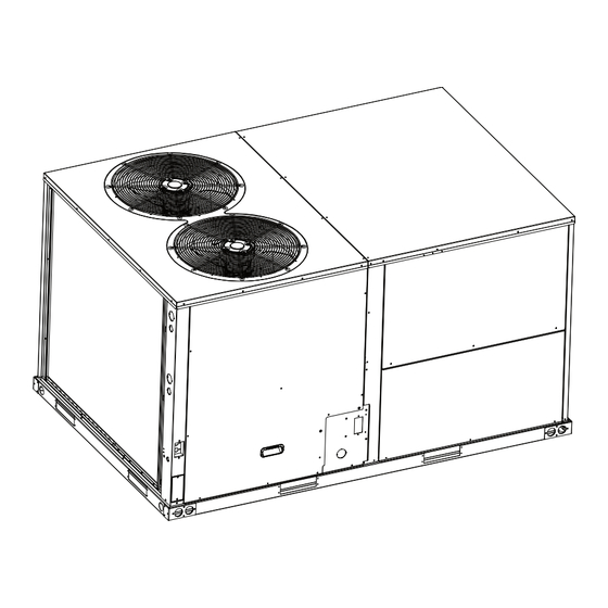
Foundation™ Packaged Rooftop
Units
Cooling and Gas/Electric
7.5 to 12.5 Tons, 60 Hz
Model Numbers: EDK090-150, GDK090-150
Only qualified personnel should install and service the equipment. The installation, starting up, and servicing of heating, ventilating, and air-conditioning equipment
can be hazardous and requires specific knowledge and training. Improperly installed, adjusted or altered equipment by an unqualified person could result in death or
serious injury. When working on the equipment, observe all precautions in the literature and on the tags, stickers, and labels that are attached to the equipment.
October 2024
SAFETY WARNING
RT-SVX096A-EN
Advertisement

Subscribe to Our Youtube Channel
Related Manuals for Trane Foundation EDK090


Summary of Contents for Trane Foundation EDK090
- Page 1 Installation, Operation, and Maintenance Foundation™ Packaged Rooftop Units Cooling and Gas/Electric 7.5 to 12.5 Tons, 60 Hz Model Numbers: EDK090-150, GDK090-150 SAFETY WARNING Only qualified personnel should install and service the equipment. The installation, starting up, and servicing of heating, ventilating, and air-conditioning equipment can be hazardous and requires specific knowledge and training.
- Page 2 (HCFCs). Not all refrigerants containing these compounds bump cap, fall protection, electrical PPE and arc have the same potential impact to the environment. Trane flash clothing). ALWAYS refer to appropriate advocates the responsible handling of all refrigerants.
- Page 3 • Do not use any phone in your building. This document and the information in it are the property of Trane, and may not be used or reproduced in whole or in • Open windows and doors. part without written permission. Trane reserves the right to •...
- Page 4 Factory Training use of the appliance by a person responsible for their Factory training is available through Trane University™ to safety. Children should be supervised to ensure that they help you learn more about the operation and maintenance do not play with the appliance.
- Page 5 Table of Contents Model Number Description ....7 Electrical Phasing (Three Phase Motors) ......29 General Information .
- Page 6 Table of Contents Monthly Maintenance ..... 46 Failures......51 Filters .
- Page 7 Model Number Description Digit 1 — Unit Type Digit 20 to 24 Digit 11— Minor Design Sequence Not Used E = Packaged Cooling, Electric Heat A = Rev A G = Packaged Gas/Electric B = Rev B Digit 12, 13 — Service Sequence Digit 2 —...
- Page 8 General Information Unit Inspection WARNING Fiberglass Wool! To protect against loss due to damage incurred in transit, perform inspection immediately upon receipt of the unit. Exposure to glass wool fibers without all necessary Check carefully for shipping damage. PPE equipment could result in cancer, respiratory, skin or eye irritation, which could result in death or Exterior Inspection serious injury.
- Page 9 General Information Evaporator Frost Control The manufacturer will not assume any responsibility for equipment damage resulting from condensate This input incorporates the Evaporator Frost Control accumulation on the unit electrical and/or mechanical mounted in the indoor coil and can be activated by closing components.
- Page 10 General Information modifications to this system will result in potentially hazardous conditions and improper equipment operation, and void all system warranties and liabilities. RT-SVX096A-EN...
- Page 11 Dimensional Data Below figure illustrates the minimum operating and service WARNING clearances for either a single or multiple unit installation. Airflow Obstruction! These clearances are the minimum distances necessary to Failure to follow instructions below could result in assure adequate serviceability, cataloged unit capacity, and death or serious injury or property damage.
- Page 12 Dimensional Data Figure 1. Typical installation clearance for single and multiple unit applications (in inches) END TO END NOTE 2,3 SIDE BY SIDE NOTE 2 NOTES: 1.FOR HORIZONTAL DISCHARGE UNIT, NOTE 1 THIS MEASURE IS REDUCED TO 1’ 6” TO MINIMIZE DUCT EXTENSIONS. 4’...
- Page 13 Dimensional Data Figure 2. Gas/electric units — overview CONDENSATE GAS CONNECTION DRAIN INSIDE CONNECTION Figure 3. Gas/electric units — overview Power Connection Hole Ø2 Ø1-3/8” Ø2 Ø1-3/8” Ø7/8” 2-5/16” 7-3/4” 23-3/4” 7-3/4” 7-3/4” 23-3/4” 7-3/4” 9-7/8” 37-15/16” 58-7/8” 88-7/16” RT-SVX096A-EN...
- Page 14 Dimensional Data Figure 4. Gas/electric units — bottom view (in inches) 88-7/16” 25-5/8” 29-5/8” 14” 3-7/16” 36-7/16” 3-7/16” NOTES: 1.THROUGH THE BASE GAS AND ELECTRICAL IS NOT STANDARD ON ALL UNITS. 2.VERIFY WEIGHT, CONNECTION, AND ALL DIMENSION WITH INSTALLER DOCUMENTS BEFORE INSTALLATION. Figure 5.
- Page 15 Dimensional Data Figure 6. Roof curb (in inches) 15 1/2” 3.000 84 13/16” 54 9/16” 32 1/4” 19 3/8” SUPPLY 3.000 45 1/8” 15 13/16” 37 15/16” RETURN 3 9/16” 14.000 1 3/4” 54 9/16” 84 13/16” Figure 7. Downflow unit clearance (in inches) CLEARANCE 68”...
- Page 16 Weights Table 1. Maximum unit and corner weights (lb) and center of gravity dimensions (in.) Weights (lb) Corner Weights Center of Gravity (in.) Tons Unit Model No. Shipping Length Width GDK090A 1087 1025 GDK102A 1124 1063 GDK120A 1157 1096 12.5 GDK150A 1237 1175...
- Page 17 Weights Figure 9. Rigging and center of gravity data CENTER OF GRAVITY CENTER OF GRAVITY WIDTH LENGTH RT-SVX096A-EN...
- Page 18 • To be repaired only by trained service At all times, Trane’s maintenance and service guidelines personnel. shall be followed. If in doubt, contact Trane technical support for assistance. • Do not puncture refrigerant tubing. All maintenance staff and others working in the local area •...
- Page 19 Verify continuity of earth bonding. The recovery equipment shall be in good working order • Replace electrical components with Trane replacement with instructions available. Equipment shall be suitable for parts, or those meeting the same ratings and qualified the recovery of the flammable refrigerant. For specific for flame arrest protection, UL LZGH2 category.
- Page 20 A2L Information • Ensure that the refrigerating system is earthed prior to the equipment are removed from site promptly and all charging the system with refrigerant. isolation valves on the equipment are closed off. • Label the system when charging is complete (if not 11.
- Page 21 A2L Information Minimum Room Area Limits unless the smallest room it serves is larger than the adjusted A threshold. This product contains a leak (Refrigerant charge greater than 3.91 lb detection system if a circuit charge is greater than 3.91 per circuit) lbs.
- Page 22 A2L Information Minimum Room Area (A ) Adjustments Multiply the altitude adjustment factor in the table below by listed on the unit nameplate or in the Installation, Use equation below to adjust the minimum room area, as Operation, and Maintenance (IOM) manual. applicable, based on the unit’s installation height, altitude, and occupancy level it serves.
- Page 23 A2L Information actions. Mitigation actions may be verified by disconnecting The refrigerant sensors do not need service. Use only the sensor. manufacturer-approved sensors when replacement is required. RT-SVX096A-EN...
- Page 24 Installation Unit Foundation When attaching the ductwork to the unit, provide a watertight flexible connector at the unit to prevent operating WARNING sounds from transmitting through the ductwork. Risk of Roof Collapsing! All outdoor ductwork between the unit and the structure should be weather proofed after installation is completed.
- Page 25 Installation Important: The first 6 inches of supply air plenum and Figure 10. Vent hood installation ductwork must be constructed of sheet metal as required by NFPA 90B. The supply air plenum or duct must have a solid sheet metal bottom directly under the unit with no openings, registers, or flexible air ducts located in it.
- Page 26 Installation Field Installed Power Wiring Protection devices must be sized according to the electrical data on the nameplate. An overall dimensional layout for the standard field • A field supplied disconnect switch must be installed at installed wiring entrance into the unit is illustrated in or near the unit in accordance with the National “Dimensional Data,”...
- Page 27 Installation Table 4. Electromechanical thermostat 24V AC conductors with electromechanical unit (continued) Distance from Unit to Control Recommended Wire Size 20 gauge 31 - 50 feet 9.5 - 15.2 m 0.50 mm^2 18 gauge 51 - 75 feet 15.5 - 22.9 m 0.75 mm^2 16 gauge 76 - 125 feet...
- Page 28 Installation Gas Heat Data Table 5. Gas heater operating data Heating Input Rate 125,000 180,000 225,000 250,000 —Btu/h Minimum Supply Gas Pressure Natural/LP 4.5/11.0 4.5/11.0 4.5/11.0 4.5/11.0 Manifold Gas Pressure Combustion Blower Suction Pressure (1 Stage) -1.3 to -1.7 -1.3 to -1.7 -1.1 to -1.5 -1.1 to -1.5 Combustion Blower Suction Pressure (2...
- Page 29 Installation Electrical Phasing (Three Phase Motors) Figure 13. Typical unit gas train configuration The compressor motor(s) and the supply fan motor are internally connected for the proper rotation when the incoming power supply is phased as A, B, C. Proper electrical supply phasing can be quickly determined and corrected before starting the unit by using an instrument such as an Associated Research Model 45 Phase Sequence Indicator and following the steps below:...
- Page 30 Installation Checklist Important: All phases of this installation must comply with NATIONAL, STATE, and LOCAL CODES. In Use the following checklist in conjunction with the general addition to local codes, the installation must checklist (“,”) to ensure that the unit is properly installed comply with National Electric Code - ANSI/ and ready for operation.
- Page 31 Installation Through-the-Base Gas Utility Table 8. Through the base gas piping dimension Option Model Dimension GDK090-150 1 3/16–in. Field Installed Connections This section contains the instructions for making field Figure 14. Through the base gas piping installation connections to the through-the-base gas utility option. WARNING Hazardous Voltage w/Capacitors! Failure to disconnect power and discharge capacitors...
- Page 32 Installation Refrigerant Sensor WARNING Leak Detection System Installed! Important: Failure to follow instructions below could result in • When there is a leak, the electric heater death or serious injury or equipment damage. will stop. When the refrigerant sensor detects a refrigerant leak, the device shuts The unit is equipped with electrically powered safety down the compressor, external motor, measures and must be powered at all times after...
- Page 33 Installation Figure 15. Refrigerant sensor installation position (1–inside; 2–outside) RT-SVX096A-EN...
- Page 34 Pre Start Verifying Proper Air Flow (Units Electromechanical Controls – with Belt Drive Indoor Fan) Test Procedure Much of the systems performance and reliability is closely Fan Test and Minimum Ventilation. Connect the short associated with, and dependent upon having the proper circuit between R and G.
- Page 35 Start-Up Electromechanical Controls - When the thermostat fan selection switch is set to the "On" position, the thermostat keeps the indoor fan relay coil (F) Sequence Of Operation energized for continuous fan motor operation. These units are offered with electromechanical controls. Economizer Set-Up - Standard Cooling without an Economizer Economizer...
- Page 36 Start-Up When the W2 contacts close, the second stage electric Table 10. Ignition module diagnostics (continued) heat contactor (BH or BH and DH) is energized, if Flame Rollout Switch open. Six blinks applicable. The thermostat cycles both the first and second stages of heat "On"...
- Page 37 Start-Up High Pressure Cutout and Temperature backwards, it will not pump and a loud rattling sound can be observed. Discharge Limit Figure 16. Compressor terminal box The high pressure controls and temperature discharge limit are wired in series between the compressor outputs on the LTB and the compressor contactors.
- Page 38 Start-Up Table 12. POE Oil recharge amount (fl. oz.) (continued) 208/230V 460V Tonnage Compressor 1 Compressor 2 Compressor 1 Compressor 2 E/GD*120 43.3 53.1 43.3 53.1 E/GD*150 53.1 43.3 53.1 43.3 Final System Setup 2. After the compressor and condenser fan have started and operated for approximately 30 minutes, observe After completing all of the pre-start and start-up procedures the operating pressures.
- Page 39 Start-Up Table 13. Maximum Refrigerant Charge (continued) A/TA Mmax lb-oz 19.5 14-0 20.4 14-10 21.4 15-5 22.3 16-0 23.2 16-10 24.2 17-5 Table 14. Minimum circulation airflow Qmin lb-oz 202.7 4-13 223.0 243.2 5-11 263.5 283.8 304.1 324.3 344.6 7-15 364.9 385.1 8-13...
- Page 40 Start-Up Table 14. Minimum circulation airflow (continued) Qmin lb-oz 16-12 770.3 17-3 790.5 Table 15. Refrigerant charge limit Model (Tons) mc/kg TAmin 1.7(system A) 1.95(system A) 2.3(system A) 3(system A) 12.5 Table 16. Minimum effective dispersal volume Table 16. Minimum effective dispersal volume (continued) lb-oz lb-oz...
- Page 41 Start-Up Important Service Precautions • No live electrical components and wiring must be exposed while charging, recovering, or purging the WARNING system. Hazardous Service Procedures! • There must be continuity of earthing. Failure to follow all precautions in this manual and on the tags, stickers, and labels could result in death or Sealed electrical components and Intrinsically safe components must be replaced.
- Page 42 Start-Up Important: Do Not use compressed air or oxygen for 5. If a vacuum is not possible, make a manifold so that purging refrigerant systems. refrigerant can be removed from various parts of the system. For appliances containing flammable refrigerants, purge refrigerants by breaking the vacuum in the system with 6.
- Page 43 Start-Up If compressors or compressor oils need to be removed, The compressor body must not be heated by an open confirm that they have been evacuated to an acceptable flame or other ignition sources to accelerate this process. level to avoid any flammable refrigerant within the lubricant. Drain oil from a system safely.
- Page 44 Maintenance WARNING WARNING Safety Hazard! Safety Precautions! Failure to follow instructions below could result in Failure to follow the safety precautions could result in death or serious injury and equipment or property serious injury, death, or property damage. damage. • Follow instructions according to the controlled For continued performance, reliability, and safety, use procedures to minimize the risk of the presence of...
- Page 45 Maintenance matched set of belts to ensure equal belt length. 6. Compare the “force” scale reading (Step 5) with the appropriate “force” value listed in the Belt tension table. When removing or installing the new belts, do not stretch If the “force” reading is outside the range, readjust the them over the sheaves.
- Page 46 Maintenance Table 18. Belt tension measurement and deflection ranges (mm/kg) Deflection Force (kg) Small P.D Range Belts Cross Super Gripbelts (mm) Gripnotch (mm) Steel Cable Gripbelts (mm) (mm) Section Min. Max. Min. Max. Min. 13.3–16.0 13.3 20.0 17.2 24.5 14.5 17.8 16.9–21.4 15.6...
- Page 47 Maintenance WARNING – ambient temperature – compressor oil level (each circuit) Hazardous Chemicals! – compressor suction and discharge pressures (each Failure to follow this safety precaution could result in circuit) death or serious injury. Coil cleaning agents can be either acidic or highly alkaline and can burn severely –...
- Page 48 Maintenance Table 19. Unit data log (continued) -schematic(s) -connections Network ID RT-SVX096A-EN...
- Page 49 Maintenance RT-SVX096A-EN...
- Page 50 Variable Frequency Drive (VFD) If installed in an appropriate environment, the VFD requires If there is no power for more than two years, use the very little maintenance. adjustable power supply to gradually increase the voltage from 0V to the rated voltage of the inverter within 2 minutes Important: Do not perform wiring, inspection, or repair to 3 minutes, and then activate the main circuit electrolytic operations while the power is on.
- Page 51 Troubleshooting WARNING verify operation of all outputs, controls, and modes. Refer to the sequence of operations for each mode, to Hazardous Service Procedures! assist in verifying proper operation. Make the Failure to follow all precautions in this manual and on necessary repairs and proceed to Step 6 and Step 7.
- Page 52 Troubleshooting Method 1 Method 2 To reset the system from the space, turn the “Mode” To reset the system at the unit, cycle the unit power by selection switch at the thermostat to the “Off” position. After turning the disconnect switch “Off” and then “On”. approximately 30 seconds, turn the “Mode”...
- Page 53 Troubleshooting Table 22. Troubleshooting chart (continued) SYMPTOM POSSIBLE CAUSE REMEDY Restriction in liquid line, expansion device or filter drier Remove or replace defective component Flow check piston size too small Change to correct size piston High head-low vapor pressure Incorrect capillary tubes Change coil assembly Check the control wiring and valve body;...
- Page 54 Troubleshooting Table 22. Troubleshooting chart (continued) SYMPTOM POSSIBLE CAUSE REMEDY Tighten all screws around burner compartment Cracked heat exchanger. Replace as necessary. Incomplete combustion results in: Aldehyde odors, Unit over-fired. Reduce input (change orifices or adjust gas Poor flame characteristics carbon monoxide, sooting flame, floating flame line or manifold pressure).
- Page 55 Wiring Diagrams Note: Contact technical support for wiring diagrams. Table 23. Wiring diagrams Type of Airflow Schematic Type Voltage Description Multi-Speed Fans Power and Control 208/230 GDK090-150, 60Hz, 2-Stage GasHeat w/VFD Multi-Speed Fans Power and Control GDK090-150, 60Hz, 2-Stage GasHeat w/VFD RT-SVX096A-EN...
- Page 56 Products Covered — This warranty is extended by Trane, and which have been returned to the warrantor. and applies to the following products: The warrantor’s warranty is conditional on the Customer...
- Page 57 Notes RT-SVX096A-EN...
- Page 58 Notes RT-SVX096A-EN...
- Page 59 Notes RT-SVX096A-EN...
- Page 60 For more information, please visit trane.com or americanstandardair.com. Trane and American Standard have a policy of continuous product and product data improvement and reserve the right to change design and specifications without notice. We are committed to using environmentally conscious print practices.
Need help?
Do you have a question about the Foundation EDK090 and is the answer not in the manual?
Questions and answers