Table of Contents
Advertisement
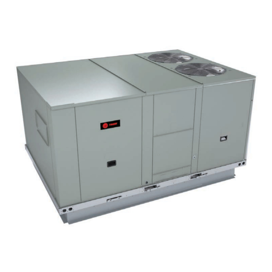
Installation, Operation, and Maintenance
Packaged Rooftop Air
Conditioners Foundation™ ™
Cooling and Gas/Electric
15 to 25 Tons, 60 Hz
Model Numbers: GBC180-300
Only qualified personnel should install and service the equipment. The installation, starting up, and servicing of heating, ventilating, and air-conditioning
equipment can be hazardous and requires specific knowledge and training. Improperly installed, adjusted or altered equipment by an unqualified person
could result in death or serious injury. When working on the equipment, observe all precautions in the literature and on the tags, stickers, and labels that
are attached to the equipment.
November 2020
S S A A F F E E T T Y Y W W A A R R N N I I N N G G
R R T T - - S S V V X X 5 5 1 1 H H - - E E N N
Advertisement
Table of Contents


Need help?
Do you have a question about the Foundation GBC180 and is the answer not in the manual?
Questions and answers