
Related Manuals for Trane Voyager TSD/TSH 060


Summary of Contents for Trane Voyager TSD/TSH 060
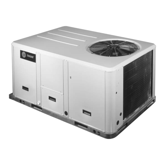
- Page 1 Installation Operation Maintenance Voyager™ I Rooftop Units Cooling-only TSD/TSH 060 072 102 120 Reversible WSD/WSH 060 072 090 Gas-fired YSD/YSH 060 072 090 102 120 RT-SVX20A-E4...
-
Page 2: General Information
Your personal safety maintenance by the user, of Trane and the proper operation of this TSD/TSH, WSKD/WSH and YSD/YSH machine require that you follow units. They do not contain full them carefully. -
Page 3: Reception
A copy of technicians a better knowledge of this letter must be sent to Trane Do not use the unit's heater as the equipment they are using, or Epinal Operations - Claims team. -
Page 4: Table Of Contents
Contents General information Foreword Warnings and Cautions Reception Warranty Refrigerant Maintenance contract Storage Training Installation Reception of units Roof curb installation Dimensions/Weights/Clearances Installing the unit Connection of duct network Condensate drain piping Gas pipework installation Filter installation Supply fan adjustment Component air pressure drops Supply fan performances Electrical connection... - Page 5 Contents Unit Options Hot water coil Electric Heater Soft Starter 0 - 25% fresh air hood Barometric relief Operation Operation with a conventional thermostat Setting the economizer Test procedures Test modes Unit Start-up Cooling without an Economizer Low Ambient Operation Cooling with an Economizer Economizer Set-Up ReliaTel™...
-
Page 6: Installation
Installation Figure 2 - Rigging General information: The Roof curb (accessory) installation must conform to all Roof curbs are available as an local standards and regulations. accessory for downflow units. The curbs can be adjustable and Reception of units supplied pre-assembled on wooden pallets, packed under plastic film. -
Page 7: Dimensions/Weights/Clearances
Installation Figure 3 - Minimum clearances Dimensions/Weights/ Clearances The structure accommodating the unit(s) must be designed to support the equipment in operation, as a minimum. Refer to Table 2 and the space requirement plan. Table 1 - Minimum recommended clearances Unit size Mimum clearances (mm) TSD/TSH 060... - Page 8 Installation Figure 4 Center of gravity length Center of gravity width Center of gravity Table 3 - Factory-installed options and accessories net weights (kg) Motorized Manual Barometric Oversized Electric Hot water Unit size Economizer Outside Air Outside Air Roof Curb Relief Motor Heaters...
-
Page 9: Installing The Unit
Vertical discharge, a panel must be and securing the other side with acquired from Trane. 3 screws. If a unit is to be converted to 4. Slide return duct cover... -
Page 10: Connection Of Duct Network
Installation Installing the unit on the ground Connection of duct • For the design of the duct network, comply with To install the unit on the ground, its network recommendations currently base must be level and supported applicable on the market, in securely. - Page 11 Installation Table 4 - Duct dimensions for downflow units (mm) Unit size Flanges TSD 060 YSD 060 WSD 060 TSD/WSD 072/090 TSD 102/120 YSD 072/090/102/120 Table 5 - Duct dimensions for downflow units (mm) Unit size TSH/WSH 060 YSH 060 TSH/WSH/YSH 072/090 TSH/YSH 102/120 Figure 8 - Duct dimensions for downflow units...
-
Page 12: Condensate Drain Piping
Installation Figure 10 - Condensate drain location Condensate drain piping A 3/4" condensate drain connection with P-trap is provided. Follow local codes and standard piping practices when running the drain line. Install a trap and be sure to fill with water before starting the unit. -
Page 13: Gas Pipework Installation
Table 50. Note: To operate with propane gas, the burner is fitted with a pressure limiter (supplied by Trane) 1 = Evaporator section 2 = Gas burner section 3 = Condenser section 4 = Gas supply connection... -
Page 14: Filter Installation
Installation Filter installation Supply fan adjustment To gain access to filters, remove the Use the following procedure to supply fan access panel on determine the proper adjustment of downflow units and the filter access the supply fan for a specific panel on the end for horizontal application. - Page 15 Installation To increase airflow To adjust belt When removing or installing the new belts, do not stretch them over Loosen variable sheave set screw The fan belts must be inspected the sheaves. Loosen the belts using and turn sheave clockwise. periodically to assure proper unit the belt tension adjustment bolts on operation.
-
Page 16: Component Air Pressure Drops
Installation Component air pressure drops Table 9 - Pressure drop through accessories Economizer Unit Airflow Filter Filter Electric Hot water 100% size EU2/G2 EU4/G4 heater coil outside air 3060 3400 3740 4080 3670 4080 4490 4900 4590 5100 5610 6120 5200 5780 6360... -
Page 17: Supply Fan Performances
Installation Supply fan performances Table 10 - TSD 060 Available static pressure External Static Pressure (Pa) 2720 0.43 0.49 0.54 1023 0.59 1060 0.64 1093 0.69 1126 0.74 3060 0.49 0.54 0.58 1028 0.64 1067 0.70 1104 0.76 1138 0.82 1171 0.87 3400... - Page 18 Installation Table 12 - TSD 072 Available static pressure External Static Pressure (Pa) 3260 0.41 0.47 0.52 0.58 0.65 0.71 0.77 3670 0.43 0.49 0.55 0.61 0.67 0.74 0.81 0.87 4080 0.51 0.58 0.64 0.71 0.77 0.84 0.91 0.99 4490 0.54 0.60 0.68...
- Page 19 Installation Table 14 - TSD 090 Available static pressure External Static Pressure (Pa) 4080 0.54 0.60 0.67 0.73 0.80 0.87 0.95 1013 1.02 4590 0.66 0.74 0.82 0.89 0.96 1.04 1010 1.11 1043 1.19 5100 0.68 0.74 0.82 0.90 0.98 1.06 1.15 1013...
- Page 20 Installation Table 16 - TSD 102 Available static pressure External Static Pressure (Pa) 4620 0.62 0.71 0.81 0.90 1.00 1.11 1.21 5200 0.64 0.73 0.83 0.93 1.03 1.13 1.24 1.35 5780 0.68 0.76 0.86 0.96 1.07 1.18 1.28 1.40 1.51 6350 0.72 0.82...
- Page 21 Installation Table 18 - TSD 120 Available static pressure External Static Pressure (Pa) 5440 0.93 1.03 1.14 1.25 1.36 1.47 6120 0.99 1.10 1.22 1.34 1.46 1.57 1.69 6800 1.01 1.11 1.21 1.32 1.44 1.56 1.69 1.82 1015 1.95 7480 1.14 1.24 1.36...
- Page 22 Installation Table 20 - YSD 060 Available static pressure External Static Pressure (Pa) 2720 1043 0.62 1078 0.67 1113 0.72 1145 0.77 1177 0.82 3060 1066 0.70 1103 0.76 1137 0.82 1169 0.87 1202 0.93 1232 0.98 3400 1052 0.73 1089 0.79 1126...
- Page 23 Installation Table 22 - YSD 072 Available static pressure External Static Pressure (Pa) 3260 0.54 0.60 0.66 0.72 0.78 1000 0.84 3670 0.58 0.64 0.71 0.78 0.84 0.91 1028 0.98 4080 0.64 0.70 0.77 0.84 0.91 0.98 1027 1.05 1058 1.13 4490 0.70...
- Page 24 Installation Table 24 - YSD 090 Available static pressure External Static Pressure (Pa) 4080 0.73 0.80 0.87 0.94 1009 1.01 1042 1.09 1073 1.17 4590 0.85 0.92 0.99 1.07 1024 1.14 1055 1.22 1086 1.30 1117 1.39 5100 0.89 0.98 1.06 1.15 1012...
- Page 25 Installation Table 26 - YSD 102 Available static pressure External Static Pressure (Pa) 4620 0.85 0.96 1.06 1.17 1.27 1.39 5200 0.92 1.02 1.13 1.23 1.34 1.46 1.58 5780 1.00 1.11 1.22 1.33 1.44 1.56 1.68 1011 1.80 6350 1.00 1.10 1.21 1.33...
- Page 26 Installation Table 28 - YSD 120 Available static pressure External Static Pressure (Pa) 5440 1.26 1.37 1.49 1.61 1001 1.73 6120 1.42 1.54 1.66 1.78 1025 1.90 1052 2.03 6800 1.48 1.60 1.73 1.86 1024 1.99 1050 2.12 1076 2.26 1101 2.39 7480...
- Page 27 Installation Table 30 - WSD 060 Available static pressure External Static Pressure (Pa) 2720 0.47 0.53 1014 0.58 1050 0.63 1085 0.68 1118 0.72 3060 0.48 0.52 0.57 1016 0.62 1056 0.68 1093 0.74 1128 0.80 1160 0.86 3400 0.55 0.60 0.65 1023...
- Page 28 Installation Table 32 - WSD 072 Available static pressure External Static Pressure (Pa) 3260 0.38 0.44 0.50 0.56 0.62 0.68 0.75 0.81 3670 0.47 0.53 0.59 0.65 0.72 0.79 0.86 1004 0.93 4080 0.50 0.56 0.63 0.70 0.76 0.83 0.91 0.98 1027 1.06...
- Page 29 Installation Table 34 - WSD 090 Available static pressure External Static Pressure (Pa) 4080 0.56 0.63 0.70 0.76 0.83 0.91 0.98 1027 1.06 4590 0.63 0.70 0.78 0.85 0.93 1.00 1.08 1027 1.15 1059 1.23 5100 0.71 0.78 0.86 0.95 1.03 1.12 1000...
-
Page 30: Electrical Connection
Installation Electrical connection Over current protection Appropriate connectors must be provided. Flexible pipe supports are The branch circuit feeding the unit The electric panel is located in the required to prevent noise must be protected in accordance unit compressor section. Remove transmission in the building's with national or local codes and the compressor access panel. - Page 31 For additional information regarding the safe discharge of capacitors, see Trane Service Bulletin PROD-SVB06A. Table 36 - Unit wiring Standard Supply Fan Motor Oversized Supply Fan Motor...
- Page 32 Installation Table 37 - Compressor and condenser motors Compressor motor Condensor fan motor Main Locked Main Locked Number Number Motor Rated Number Number Motor Rated Unit Model power rotor power rotor amps amps and size supply amps supply amps motors phases (kW) motors...
-
Page 33: Controls
The control circuit is 24 V AC. Unit accessories mounted on site, other includes a 400/24 V transformer. than those proposed by Trane. WARNING! The unit disconnect Unit controlled by thermostat switch must be opened and locked open. - Page 34 TCI-R board. A communication bus (J7 connector). (twisted shielded pair) must link Trane THS03 and THP03 thermostats each TCI-R to the Trane Roof Top are directly connected to RTRM Manager (RTM) or to the board (J6 connector). communication gateway (in the case of an external BAS).
-
Page 35: Co 2 Sensors
Controls sensors The CO sensor is designed to operate with a nominal 24 Vac supply. The power supply should Wall-mounted and duct-mounted maintain the voltage between 20 to sensors 26 Vac. Power supply requirements CAUTION! Make sure that you Table 41 - CO sensor wire size connect the power wire only to the Maximum... - Page 36 Controls Wiring the wall-mounted CO Wiring the duct-mounted CO sensor sensor 1. Connect the common wire from DVC setpoint potentiometer on the controller to the ground economizer module can be adjusted terminal (terminal 0) (Figure 16). as follows: 2. For voltage output, connect the 0% - 500ppm, 50% - 1000 ppm, signal wire to terminal V.
- Page 37 Controls Figure 17 - Wall-mounted CO sensor Mounting the wall-mounted sensor 1. Select a proper location in the room to mount the CO sensor. Look for an interior wall with good air circulation, approximately 1.4 m from the floor. 2. Remove the back plate from the sensor and thread the power wires and output signal wire through the hole in the back...
- Page 38 (42 mm) accurate and traceable calibration in. (22 mm) gases in a laboratory. Consult Trane BAS for further details. (42 mm) Figure 20 - Duct-mounted CO sensor insertion depth in.
-
Page 39: Remote Potentiometer
Controls Remote potentiometer Note: This potentiometer allows to adjust the permanent fresh air To install the remote potentiometer, intake from 0 to 50%. cut the jumper WL on the 0 W corresponds to closed fresh air economizer ECA board, and connect damper. -
Page 40: Fire Thermostat
Controls Figure 24 - Connection of fire thermostat Fire thermostat Note: Do not permit element guard with TCI board to touch internal parts. Do not There are two sensors in the fire locate sensor where the air thermostat Kit: Sensor X13100040- circulation is restricted by baffles. -
Page 41: Clogged Filter Detector
Controls Clogged filter detector Smoke detector This device is mounted in the This device is used to detect smoke indoor fan section. The sensor in the air stream. It includes a measures the difference in pressure factory mounted detector connected before and after the filter section. -
Page 42: Thermostats
Controls Thermostats "THS" are non programmable thermostats, "THP" are 6 thermostats are available: programmable. THS01/THP01, THS02/THP02 and 01 and 02 series are conventional THS03/THP03. thermostat, 03 series are dedicated to the controller. Table 42 - Thermostat features THS01 THP01 THS02 THP02 THS03 THP03... -
Page 43: Communication Interfaces
Tracker or Varitrac systems. mounted in the main control panel, needed to allow communication DTS: Duct temperature sensor to be between a TRANE Integrated used with THS/THP 03. Comfort system (TRACKER or TZS02: Remote room temperature Varitrac CCP2) and the unit. (COM3-... -
Page 44: Unit Options
Unit Options Hot water coil The hot water coil is factory mounted in the discharge section. (Down flow units only) Two holes are provided to connect the hot water coil. They are located In order to prevent water to freeze at the base of the unit. -
Page 45: Electric Heater
Unit Options Electric Heater Soft Starter Electric heaters are fitted on the fan The soft starter is used to achieve a discharge. progressive supply fan start and a reduced starting current as well as Heaters have two heating stages the motor starting torque. This and provided with two types of option is well adapted for textile overheat thermostats:... -
Page 46: 25% Fresh Air Hood
Unit Options 0 - 25% fresh air hood This option includes for the hood itself, a wire mesh and a slidable The 0-25% fresh air hood allows to damper. introduce fresh air into the unit. The slidable damper has to be This is a manual device fitted on the adjusted manually by removing the back of the unit, sized for a... -
Page 47: Barometric Relief
Unit Options Barometric relief This option includes exhaust hoods and gravity dampers located in the The barometric relief allows to return air section. When the minimize overpressure in the pressure of the building increase, building caused by the introduction the gravity dampers open and of fresh air. -
Page 48: Operation
If the • Space Temperature Averaging thermostats. In addition, non-Trane economizer is enabled, a Y2 call for capabilities are not available on Building Controllers typically 2nd stage cooling will start the first most mechanical thermostats. - Page 49 Operation Conventional thermostat signals Logic is also provided to cause Thermostat signals are as follows: represent direct calls for unit appropriate unit functions when R 24VAC power to thermostat functions. In their simplest inappropriate thermostat signals are Y1 Call for compressor 1 or first applications, thermostat contacts provided.
-
Page 50: Setting The Economizer
Operation Unoccupied mode Setting the economizer or If the thermostat being used is 0-50% motorized hood programmable, it will have its own (option) strategy for unoccupied mode and will control the unit directly. If a The ECA board is mounted on the mechanical thermostat is being damper actuator. -
Page 51: Eca Board Led
Operation Table 47 - ECA board LED To check the damper is functioning correctly, the ECA is equipped with OFF: No Power or Failure an indicator light in the middle of the board. This light operates as in Normal, OK to Economize Table 42. -
Page 52: Test Procedures
Operation Test procedures WARNING! If any operating checks Test mode procedure at the must be performed with the unit ReliaTel™ control board operating, it is the technician's Operating checklist before start-up Operating the unit from the roof responsibility to recognize any •... -
Page 53: Test Modes
Operation Table 48 - Service Test Guide for Component Operation on cooling only units Test modes There are 2 methods in which the "Test" mode can be cycled with the test button: 1. Step Test Mode This method initiates the different components of the unit, one at a time, by temporarily shorting across the two test terminals for two to... -
Page 54: Unit Start-Up
Operation Figure 32 - Gas valve Unit start-up Note: Unit to be installed outside only. Verification of gas valve settings - G20 - 7.5mbar G20 - 7.5mbar Note: Expansion valve must be G25 -10.5mbar G25 -10.5mbar (Reserved for the qualified gas adapted to the type of gas used: technician) •... - Page 55 Operation Starting the unit in cooling mode Operating pressures Final installation checklist • Are all power cables tightened? Before start-up, ensure that all After the unit has operated in Check torque of power cables power cables are tightened. cooling mode for a short period of contact ! time, install pressure gauges on the Verify that the unit airflow rate is...
-
Page 56: Cooling Without An Economizer
Operation ReliaTel™ is a microelectronic Cooling without an Evaporator Fan Operation control feature, which provides Economizer When the fan selection switch is set operating functions that are to the "Auto" position, the RTRM significantly different from When the system switch is set to energizes the (K6) relay coil conventional electro-mechanical the "Cool"... -
Page 57: Low Ambient Operation
Operation Low Ambient Operation Cooling with an The ECA continues to modulate the economizer damper open/closed to Economizer During low ambient operation, keep the mixed air temperature that outside air temperature below 13ºC, is calculated by the RTRM. The economizer is utilized to control the RTRM will cycle the compressor the zone temperature providing the If economizing is not possible, the... -
Page 58: Economizer Set-Up
Operation Economizer Set-Up 3. Comparative Enthalpy - By Ignition Module utilizing a humidity sensor and a Adjusting the minimum position Two Stage (IGN) runs self-check temperature sensor in both the potentiometer located on the unit (including verification that the gas return air stream and the economizer Actuator (ECA) sets the valve is de-energized). -
Page 59: Final Installation Checklist
Operation Refer to the ignition control module Final installation checklist diagnostics section for the LED • Is the condenser fan and indoor diagnostic definitions. blower operating correctly, i.e.: correct rotation and without When the fan selection switch is set undue noise? to the "Auto"... -
Page 60: Maintenance
Maintenance To keep the unit operating safely End user routine and efficiently, the manufacturer maintenance recommends that a qualified service technician check the entire system Some of the periodic maintenance at least once each year, or more functions for the unit can be frequently if conditions warrant it. -
Page 61: Service Technician Maintenance
Maintenance Note: Do not attempt to clean Service technician disposable filters. Permanent filters maintenance can be cleaned by washing with a mild detergent and water. Ensure Before the cooling season, your that the filters are thoroughly dry service technician may examine the before reinstalling them in the unit following areas of your unit: (or duct system). -
Page 62: Troubleshooting
Maintenance Troubleshooting 5. If no failures are indicated, use System Status Checkout Procedure one of the TEST mode "System Status" is checked by using The RTRM has the ability to provide procedures described in the unit one of the following two methods: the service personnel with some "Start-Up"... - Page 63 Maintenance Below is the complete listing of Cooling Failure Simultaneous Heat and Cool Failure failure indication causes: 1. Cooling and heating set point 1. Emergency Stop is activated (slide pot) on the zone sensor System failure has failed. Refer to the "Zone Method 2 Sensor Test Procedure"...
- Page 64 Maintenance Service Failure Resetting Cooling and Ignition Zone Temperature Sensor (ZTS) Lockouts Service Indicator Measure the voltage between terminals J6-10 & J6-6. Cooling Failures and Ignition The ZSM SERVICE LED is a generic indicator that will signal the closing Clogged Filter = Approximately Lockouts are reset in an identical of a Normally Open switch at any 32 VDC.
- Page 65 Maintenance Table 55 - Thermistor Resistance / Zone Temperature Sensor (ZTS) Test Temperature Chart Note:These procedures are not for Temperature/resistance coefficient is programmable or digital models negative. and are conducted with the Zone Sensor Temperature Resistance Module electrically removed from (°C) (kOhms) the system.
- Page 66 Maintenance To Test Humidity Sensors Return Air Humidity Sensor RAH/RAE Outdoor Humidity Sensor OAH/OAE To test this circuit, place a DC milliamp meter in series with either of the leads to the humidity sensor. If the reading is 0ma, polarity may be reversed. Reverse + & - and retest. If the reading does not correspond to the table below, check the output voltage from the ECA with the sensor disconnected.
- Page 67 Notes RT-SVX20A-E4...
- Page 68 Literature Stocking Location Europe Trane has a policy of continuous product and product data improvement and reserves the right to change design and specifications without notice. Only qualified technicians should perform the installation and servicing of equipment referred to in this publication.