Advertisement
Quick Links
Specifications
Wiring Input
Rated Input Voltage
Frequency Range
Rated Input Current
Power Consumption
Display Update Rate
Operating / Storage Temperature
Humidity
Protection Degree (IEC/EN60529)
Pulse Output voltage range /
Max Current
Pulse Resolution
Pulse Duration
Modbus (RI-D35-100-C Only)
Interface Standard & Protocol
Communication Address
Transmission Mode
Data Type
Transmission distance
Transmission Speed
Parity
Stop Bits
PRODUCT SAFETY
Safety related notification, symbols and instructions that appear in this
operating manual or on the equipment must be strictly followed to
ensure the safety of personnel as well as the instrument. If the
equipment is not used in a manner specified by the manufacturer it may
impair the protection provided by the equipment
•
Do not use the equipment if there are mechanical damage
•
Do not exceed the stated maximum ratings of the device
•
No repairs, maintenance or adjustments are possible
•
Read the complete instruction manual prior to installation or
operating the unit
•
The equipment in its installed state must not come into close
proximity to any heating sources, oils, steam, caustic vapours or
other unwanted process by-products
•
Do not use in hazardous or classified location where explosion or
other dangers can be triggered by the device
EO&E: Document subject to change
1Ø2W DIRECT
CONNECTION
RTU
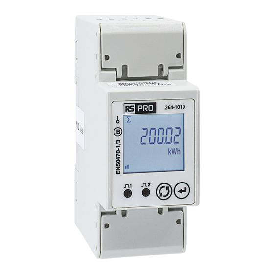
264-1019
1Ø 2 wire
230V AC ±20%
50 or 60Hz (MID approved @ 50Hz)
Ib = 10A, Imin = 0.5A, Imax = 100A
< 8VA
1 sec all parameters
-10...55°C / -20...75°C
0...85% non-condensing
IP54 (front of Housing), IP20 (terminals)
Volt-free - require external 5...24V DC
100mA max
1: 1000 pulses/kWh (Fixed)
2: 1/10/100/1000 pulses/kWh or
pulses/kVArh (configurable)
0.05...2 sec (configurable)
RS485 / Modbus RTU
1...255
Half Duplex
FLOAT & INTEGER
500m max
9600 / 19200 bps
None / Odd / Even
1 / 2
264-1019
Installation must comply
with MID certified
requirements
All terminal covers must be
fitted and secured with
sealing hasp.
Voltage V
L-N
Current
Frequency for L-N > 20V, L-L > 35V
Active, Reactive and Apparent Power
Power Factor
Active Energy
Reactive Energy
Apparent Energy
INSTALLATION PRECAUTIONS
Risk of electric shock!
Only to be installed by a competent person
•
To prevent the risk of electrocution, always isolate and lock-off the
power supply to the equipment prior to undertaking any work
•
Always confirm absence of electricity prior to starting work using
appropriate voltage detection equipment
•
Wiring shall be done strictly according to the terminal layout
•
Confirm that all connections are correct before energizing the
equipment
•
Routing of cables shall be way from any internal EMI source
•
Copper cable should be used
•
All wiring to be in accordance with applicable local standards
Instruction Manual
Accuracy
±0.5% of full scale
±0.5% of full scale
±0.1% of full scale
1% of full scale
±0.01 of Unity
EN50470-3: Cl.B
EN62053-23: Cl.2
Class 1
264-1019-IM-V02
1
Advertisement

Related Manuals for RS PRO 264-1019


Summary of Contents for RS PRO 264-1019
- Page 1 264-1019 Instruction Manual Installation must comply 1Ø2W DIRECT with MID certified CONNECTION requirements 264-1019 All terminal covers must be fitted and secured with sealing hasp. Specifications Accuracy 1Ø 2 wire Voltage V ±0.5% of full scale Wiring Input Rated Input Voltage 230V AC ±20%...
- Page 2 Ø 2mm 12mm Booster required above max distance or devices Daisy Chain Star Network COMM Wiring Terminals Ø 6mm max Ø 2mm max Ferrule for Topology 4 | 5 Stranded Cable ✓ Modbus 0.9 Nm max 0.4 Nm max 264-1019-IM-V02...
- Page 3 MD Active Power Blinks at rate of HOLD Ʃ MD Reactive Power kVAr kVAh 10 Sec Apparent Energy Display Scroll MANUAL < > AUTO Active Power MD Apparent Power HOLD 10 Sec Serial # Idle 1min >> Reactive Power kVAr >> 264-1019-IM-V02...
- Page 4 264-1019-IM-V02 Rayleigh Instruments Limited (Head Office) Rayleigh Instruments Limited SP. Z o.o. (European Office) Raytel House, Cutlers Road, South Woodham Ferrers, Chelmsford, Essex. CM3 5WA Ul. Aleje Jerozolimskie 214, Warsaw, Poland, 02-486 W: www.rayleigh.com E: sales@rayleigh.com W: www.rayleigh.pl E: sales@rayleigh.pl...
Need help?
Do you have a question about the 264-1019 and is the answer not in the manual?
Questions and answers