Advertisement
Quick Links
Installation must comply with MID certified requirements
Once Configuration Mode is entered, 'Configuration Lock' will activate
after 15 minutes or if meter is switched off. No further adjustment is
possible for the lockable settings. Unlock only by returning to supplier.
Specifications
Wiring Input
Rated Input Voltage
Frequency Range
CT Primary
CT Secondary
VT Primary
VT Secondary
Display Update Rate
Operating / Storage Temperature
Humidity
Protection Degree (IEC/EN60529)
Communication
PRODUCT SAFETY
Safety related notification, symbols and instructions that appear in this
operating manual or on the equipment must be strictly followed to
ensure the safety of personnel as well as the instrument. If the
equipment is not used in a manner specified by the manufacturer it may
impair the protection provided by the equipment
•
Do not use the equipment if there are mechanical damage
•
Do not exceed the stated maximum ratings of the device
•
No repairs, maintenance or adjustments are possible
•
Read the complete instruction manual prior to installation or
operating the unit
•
The equipment in its installed state must not come into close
proximity to any heating sources, oils, steam, caustic vapours or
other unwanted process by-products
•
Do not use in hazardous or classified location where explosion or
other dangers can be triggered by the device
EO&E: Document subject to change
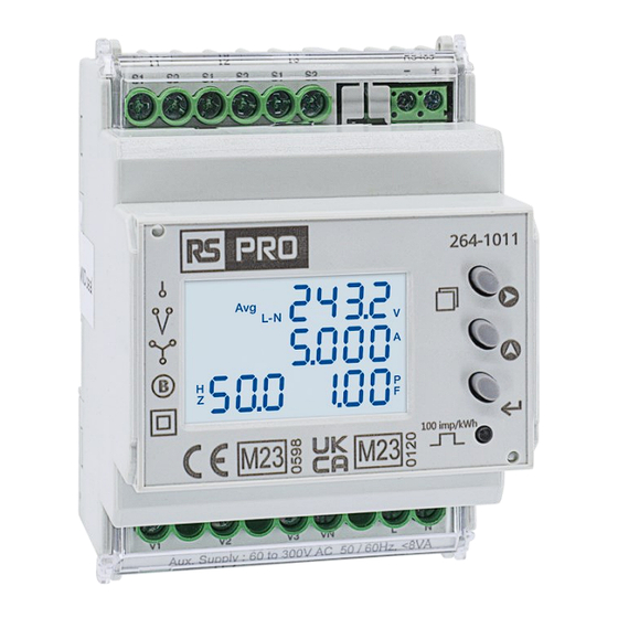
264-1011
Configuration Lock
>> see 'Configuration'
for Lockable Settings
3Ø 4 wire (MID Approved)
3Ø 3 wire, 2Ø 3 wire
1Ø 2 wire (MID Approved)
3x 85...240V AC (L-N), 147...415V AC (L-L)
47...63Hz (MID approved @ 50Hz)
1A/5A...6,000A configurable
1A or 5A (MID Approved @ 5A only)
max rating x1.2
100...600V AC (L-L) configurable
100...500V AC (L-L) configurable
1 sec all parameters
-10...55°C / -20...75°C
0...85% non-condensing
IP54 (front of Housing), IP20 (terminals)
Modbus RTU over RS485
264-1011
RTU
Voltage V L-N and V L-L
Current
Frequency for L-N > 20V, L-L > 35V
Active, Reactive and Apparent Power
Power Factor
Active Energy
Reactive Energy
Apparent Energy
Wh Resolution and Default Pulse Weight
CT Ratio x VT Ratio
<15
Wh / VArh / VAh
0.01k
INT
0.01k
Example
If CT = 100/5A (CT ratio = 20) & VT = 350/350V (VT Ratio = 1)
Wh resolution = 0.1kWh (20 x 1 = <150)
INSTALLATION PRECAUTIONS
Risk of electric shock!
Only to be installed by a competent person
•
To prevent the risk of electrocution, always isolate and lock-off the
power supply to the equipment prior to undertaking any work
•
Always confirm absence of electricity prior to starting work using
appropriate voltage detection equipment
•
Wiring shall be done strictly according to the terminal layout
•
Confirm that all connections are correct before energizing the
equipment
•
Routing of cables shall be way from any internal EMI source
•
Copper cable should be used
•
All wiring to be in accordance with applicable local standards
Instruction Manual
All terminal covers provided
must be fitted. All cable
connections and terminal
covers of the meter and the
CT must be secured with
sealing hasp.
Accuracy
±0.5% of full scale
±0.5% of full scale
±0.1% of full scale
1%
±0.01 of Unity
EN50470-3: Cl.B
EN62053-23: Cl.2
Class 1
<150
<1500
<15000
0.1k
1k
0.01M
0.01k
0.01k
0.01M
264-1011IM-V01
>15000
0.1M
0.01M
1
Advertisement

Subscribe to Our Youtube Channel
Related Manuals for RS PRO 264-1011


Summary of Contents for RS PRO 264-1011
- Page 1 264-1011 Instruction Manual 264-1011 Installation must comply with MID certified requirements Configuration Lock All terminal covers provided must be fitted. All cable >> see ‘Configuration’ connections and terminal for Lockable Settings covers of the meter and the CT must be secured with sealing hasp.
- Page 2 WIRING 1P2W, 1 CT Fuse class CC UL / fast acting 600V Rating 0.5A Voltage and Single Core current must be 0.2 > 4mm from same Ø 2.5mm Max phase Stranded 0.25 > 2.5mm Ø 2.5 mm 0.8 Nm = MID Approved Modbus 500m Max, ≤...
- Page 3 MECHANICAL INSTALLATION DIN rail mounted, this device must be installed within DISMOUNT a suitable IP rated enclosure. Indoor use only. The meter is intended to be installed in Mechanical Environment ‘M1’, with Shock and Vibrations of low significance, as per 2014/32/EC Directive. The meter is intended to be installed in Electromagnetic Environment ‘E2’, as per 2014/32/EC Directive.
- Page 4 OPERATION 1 Display Symbols: Avg Average of 3-phase tOt Total of 3-phase MD Max/Min Demand L-N Line to Neutral RS485 communication in progress 2 Measurement Units (refer to Functions Table below) V, kWh, kVArh, kVAh, A, Hz, kW, kVAr, kVA 3 Navigation Buttons: Change PARAMETER Change PAGE...
Need help?
Do you have a question about the 264-1011 and is the answer not in the manual?
Questions and answers