
Subscribe to Our Youtube Channel
Related Manuals for RS PRO RSST-2000


Summary of Contents for RS PRO RSST-2000
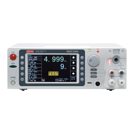
- Page 1 User Manual RSST-2000 Stock number: 2010446 RSST-2001 2010449 RSST-2003 2010448 RSST-2002 2010450 RSST-2004 rspro.com...
-
Page 2: Table Of Contents
Table of Contents Table of Contents SAFETY INSTRUCTIONS ............5 GETTING STARTED ..............9 RSST-2000 Series Overview ......... 10 Front Panel Overview ............ 14 Rear Panel Overview ............. 18 Set Up ................21 OPERATION ................28 Menu Tree ..............30 Test Lead Connection ............ - Page 3 RSST-2000 Series User Manual RSST-2001/2002/2003 Dimensions ......237 RSST-2004 Dimensions ..........238 Certificate Of Compliance ........... 239 INDEX ..................240...
-
Page 4: Safety Instructions
SAFETY INSTRUCTIONS AFETY INSTRUCTIONS This chapter contains important safety instructions that you must follow during operation and storage. Read the following before any operation to ensure your safety and to keep the instrument in the best possible condition. Safety Symbols These safety symbols may appear in this manual or on the instrument. - Page 5 Do not disassemble the RSST-2000 unless you are qualified. Position The rear position of the RSST-2000 should be Guideline placed in an area with easy accessible for power disconnection, that is, unplugging the power cord with ease. WARNING ...
- Page 6 SAFETY INSTRUCTIONS (Measurement categories) EN 61010-1:2010 specifies the measurement categories and their requirements as follows. The RSST-2000 does not fall under category II, III or IV. Measurement category IV is for measurement performed at the source of low-voltage installation.
- Page 7 RSST-2000 Series User Manual equipment is normally protected against exposure to direct sunlight, precipitation, and full wind pressure, but neither temperature nor humidity is controlled. Storage Location: Indoor environment Temperature: -10°C to 70°C Relative Humidity: ≤ 85% (no condensation) ...
-
Page 8: Getting Started
/ rear panel introduction. After going through the overview, please read the safety considerations in the Set Up chapter. RSST-2000 Series Overview ......... 10 Series lineup ..............10 Lineup Overview ............11 Main Features ..............11 Accessories .............. -
Page 9: Rsst-2000 Series Overview
See the following Lineup Overview for more details. The RSST-2000 Series can store up to 100 manual tests, as well as run up to 10 manual tests sequentially as an automatic test, allowing the safety analyzers to accommodate any number of safety standards, including IEC, EN, UL, CSA, GB, JIS and others. -
Page 10: Lineup Overview
GETTING STARTED Lineup Overview Model name CONT RSST-2001 RSST-2002 RSST-2003 RSST-2004 Main Features Performance ACW: 5kVAC DCW: 6kVDC IR: 50V~1200V (50V steps) GB: 3A~32A ... -
Page 11: Accessories
RSST-2000 Series User Manual Interface Remote control start/stop interface terminal RS232/USB interface for programming Optional GPIB interface for programming Signal I/O port for pass/fail/test monitoring and start/stop control/interlock Accessories Standard Part number Description Accessories GHT-115x1 Test lead... -
Page 12: Package Contents
GETTING STARTED Package Contents Check the contents before using the RSST-2000 series. Opening the box Contents RSST-2000 unit GHT-115 test leads x1 (single unit) Quick Start Guide GTL-215 GB test leads x1 (RSST-2004) CTC (Calibration ... -
Page 13: Front Panel Overview
RSST-2000 Series User Manual Front Panel Overview Item Description STOP Button START Button POWER Switch Test Function Keys (Green Zone) Display Mode Keys (AUTO, MANUAL, SYSTEM in Red Zone) Soft Keys (Blue Zone) USB A-Type Host Port PASS/FAIL Indicators REMOTE Terminal... - Page 14 GETTING STARTED The STOP button is used to STOP button stop/cancel tests. The STOP button will also put the safety analyzer in the READY status to begin testing. The START button is used to start START button tests. The START button can be used to start tests when the tester is in the READY status.
- Page 15 RSST-2000 Series User Manual Pass/Fail The PASS and FAIL indicators light up upon a PASS or FAIL test result indicators at the end of a manual test or automatic test. REMOTE The REMOTE terminal is used to terminal connect to a remote controller.
- Page 16 GETTING STARTED OUTPUT and All models The OUTPUT terminal (red) RETURN and RETURN terminal (black) are used for CONT (Continuity) terminals test. SENSE H/L and The SENSE H, SENSE L, RSST-2004 only SOURCE H/L SOURCE H and SOURCE L, terminals are used for GB terminals (Ground Bond) test.
-
Page 17: Rear Panel Overview
RSST-2000 Series User Manual Rear Panel Overview Item Description HIGH VOLTAGE Output Terminal HIGH VOLTAGE Indicator SENSE H & Output Terminal SENSE L & RETURN Terminal SOURCE H (RSST-2004 only) SOURCE L (RSST-2004 only) RS-232 Port USB B-Type Interface Port... - Page 18 GETTING STARTED The SIGNAL I/O port is used to SIGNAL I/O port monitor the tester status (PASS, FAIL, TEST) and input (START/ STOP signals). It is also used with the Interlock key. USB B-Type port The USB B-Type port is used for remote control.
- Page 19 RSST-2000 Series User Manual HIGH VOLTAGE The HIGH VOLTAGE terminal output is used for outputting output terminal the testing voltage in ACW, DCW and IR tests. The terminal is recessed for safety and used in conjunction with the RETURN terminal.
-
Page 20: Set Up
GETTING STARTED Set Up Tilting the Stand Horizontal Place the unit on a flat surface horizontally. position Tilt stand Gently pull the 2 stands out from the bottom and the unit will be placed in the tilt stand position. position... -
Page 21: Line Voltage Connection And Power Up
RSST-2000 Series User Manual Line Voltage Connection and Power Up Background The RSST-2000 accepts line voltages of 100 - 240V at 50Hz or 60Hz. Connect the power cord to the Steps AC Mains Input socket on the rear panel. If the power cord does not... -
Page 22: Installing The Optional Gpib Card
Follow the instructions below to install the GPIB card. Before installing optional GPIB card ensure the WARNING RSST-2000 is turned off and disconnected from power. Steps Remove screws from the rear panel cover plate. Insert the GPIB card into the opening of rear panel. -
Page 23: Workplace Precautions
RSST-2000 Series User Manual Workplace Precautions Background The RSST-2000 is a high voltage instrument that outputs dangerous voltages. The following section describes precautions and procedures that must be followed to ensure a safe work environment. The RSST-2000 generates voltages in excess of WARNING 5kVAC or 6kVDC. -
Page 24: Operating Precautions
GETTING STARTED Operating Precautions Background The RSST-2000 is a high voltage instrument that outputs dangerous voltages. The following section describes precautions and procedures that must be followed to ensure that the tester is operated in a safe manner. The RSST-2000 generates voltages of up to WARNING 5kVAC or 6kVDC. - Page 25 When DCW or IR tests are performed, the DUT, test leads and probes become highly charged. The RSST-2000 has discharge circuitry to discharge the DUT after each test. The time required for a DUT to discharge depends on the DUT and test voltage.
-
Page 26: Basic Safety Checks
GETTING STARTED Basic Safety Checks Background The RSST-2000 is a high voltage device and as such, daily safety checks should be made to ensure safe operation. Ensure all test leads are not broken and are free from defects such as cracks or splitting. - Page 27 RSST-2000 Series User Manual PERATION Menu Tree ..............30 Menu Tree Overview ............. 31 Test Lead Connection ........... 35 ACW, DCW, IR Connection ........... 35 GB Connection............... 36 CONT Connection ............37 Manual Tests ..............38 Setting the Test Function ..........39 Choose/Recall a Manual Test Number ......
-
Page 28: Operation
OPERATION Choose/Recall an AUTO Test ........94 Creating an AUTO Test File Name........ 95 Adding a Step to the AUTO Test ........96 Continuous AUTO Tests ..........97 AUTO Test Page Editing ..........100 Running an Automatic Test ......... 104 Automatic Test Results .......... -
Page 29: Menu Tree
RSST-2000 Series User Manual Menu Tree This section describes the overall structure of the operation statuses and modes for the RSST-2000 safety analyzers. The testers have two main testing modes (MANU, AUTO), one system mode (SYSTEM) and 5 main operation statuses (READY, TEST,... -
Page 30: Menu Tree Overview
OPERATION Menu Tree Overview MANU mode is used to create and/or execute a MANU Mode single test. Only under MANU mode can parameters be edited for each manual test. MANU mode AUTO Mode AUTO mode indicates that the tester is automatic, which consists of a sequential AUTO test of up to 10 MANU steps. - Page 31 RSST-2000 Series User Manual READY Status When the tester is in READY status of MANU or AUTO test, it is ready to begin testing. Pressing the (Yellow Color) START button will begin testing and put the tester into TEST status. Pressing the AUTO key will change from MANU –...
- Page 32 OPERATION PASS status in MANU test PASS status in AUTO test FAIL Status When a MANU test result is beyond the range of (RED Color) HI and LOW sets, the FAIL status is shown on display. For AUTO test, the FAIL status is shown when any of the test steps fails, even only one of them.
- Page 33 RSST-2000 Series User Manual STOP status in AUTO test...
-
Page 34: Test Lead Connection
OPERATION Test Lead Connection This section describes how to connect the RSST-2000 to a DUT for withstanding, insulation resistance, ground bond as well as continuity testing. ACW, DCW, IR Connection Background ACW, DCW and IR tests use the HIGH VOLTAGE terminal and RETURN terminal with the GHT-115 test leads. -
Page 35: Gb Connection
RSST-2000 Series User Manual GB Connection Background GB tests use the SENSE H/L and SOURCE H/L terminals with the GTL-215 test leads. GB Connection RSST-2000 Source H Sense H Source L Sense L Steps Turn the power off on the safety analyzer. -
Page 36: Cont Connection
OPERATION CONT Connection Background CONT tests use the OUTPUT and RETURN terminals with the GTL-115 test leads. CONT RSST-2000 Connection Output Return terminal Steps Turn the power off on the safety analyzer. Connect the OUTPUT test lead (white) to the OUTPUT terminal. -
Page 37: Manual Tests
RSST-2000 Series User Manual Manual Tests This section describes how to create, edit and run a single ACW, DCW, IR, GB and CONT manual tests. Each Manual setting described in this chapter only applies to the selected manual test –... -
Page 38: Setting The Test Function
OPERATION Setting the Test Function Background There are five test functions, AC Withstand, DC Withstand, Insulation Resistance, Ground Bond and Continuity tests. Steps If the tester is in AUTO or SYSTEM mode, press the MANUAL key to put the tester into MANU mode. To choose the test function, press the ACW, DCW, IR, GB or CONT key on the front panel. -
Page 39: Choose/Recall A Manual Test Number
RSST-2000 Series User Manual Choose/Recall a Manual Test Number Background ACW, DCW, IR, GB and CONT tests can only be created and edited in the MANU mode. MANU number 001 to 100 can be saved and thus be loaded when editing/creating a MANU test or AUTO test. -
Page 40: Creating A Manu Test File Name
OPERATION Creating a MANU Test File Name Background Each manual test can have a user-defined name (default: MANU_NAME) up to 10 characters long. See the available list of characters below. Character List 0 1 2 3 4 5 6 7 8 9 A B C D E F G H I J K W X Y Z a b c d e f g h i j k... -
Page 41: Setting The Upper And Lower Limits
RSST-2000 Series User Manual Setting the Upper and Lower Limits Background There is both a LOW and HI judgment setting. When the measured value is below the LOW SET setting, the test will be judged as FAIL. When the value exceeds the HI SET setting the test will be judged as FAIL. - Page 42 OPERATION LOW SET cursor Use the scroll wheel to set the LOW SET limit. ACW (LOW) 000µA~41.99mA DCW (LOW) 000µA~10.99mA 000.1MΩ~49.99GΩ IR (LOW) 000.0mΩ~649.9mΩ GB (LOW) 00.00Ω~79.99Ω CONT (LOW) *Please note that the resolution of the measured Note value depends on the resolution of HI SET setting. The LOW SET setting is limited by the HI SET Note setting.
-
Page 43: Setting The Test Time
RSST-2000 Series User Manual Setting the Test Time Background This setting is used to set the test time for a test. The test time determines how long the test voltage or current is applied to the DUT. This test time... - Page 44 OPERATION Use the scroll wheel to set the TEST TIMER value. OFF, 000.3s~999.9s OFF, 000.3s~999.9s 000.3s~999.9s 000.3s~999.9s CONT 000.3s~999.9s With the ACW test function, when the test current Note is beyond 30mA, the Ramp Up Time + Test Time cannot exceed 240 seconds. At this current level, the tester also needs to pause after a test for a time equal to or greater than the output time.
-
Page 45: Setting The Ramp Up Time
RSST-2000 Series User Manual Setting the Ramp Up Time Background The Ramp Up time is the total time taken for the tester to reach the test voltage level. The Ramp Up time can be set from 000.1 to 999.9 seconds. The Ramp Up time is only applicable for ACW, DCW and IR tests. - Page 46 OPERATION Ramp Time After pressing START to begin a test with set Duration RAMP TIME, a section at the lower right corner of display shows the counting duration of RAMP Indicator TIME, which will run to the set value followed by the test time.
-
Page 47: Setting The Ramp Down Time
RSST-2000 Series User Manual Setting the Ramp Down Time Background The Ramp Down time is the time taken for tester to gradually lower down ouput test voltage from the set highest level to zero volt. The Ramp Down time can be set from 000.0 to 999.9 seconds. The Ramp DOWN time is only applicable for ACW, DCW and IR tests. - Page 48 OPERATION 000.0s~999.9s 000.0s~999.9s 000.0s~999.9s Ramp Down After the set TEST TIME is fully completed, a Duration section at the lower right corner of display shows Indicator the counting duration of RAMP DOWN, which will run to the set value by user. See the screenshot shown below.
-
Page 49: Setting The Test Voltage Or Test Current
RSST-2000 Series User Manual Setting the Test Voltage or Test Current Background The test voltage can be set from 0.050kV to 5.1kV for ACW, 0.050kV to 6.1kV-12.1kV for DCW and 0.050 to 1.2kV for IR (50V steps*). For GB tests the test current can be set from 3A to 33A. - Page 50 OPERATION At least 0.3 seconds is needed to reach a set voltage of 50V/10mA. At least 0.3 seconds is needed to reach a set voltage of 50V/2mA. Test current for CONT is fixed at 100mA When setting the current, be aware that a Note maximum of 200VA can be set for ACW and 50W for DCW respectively.
-
Page 51: Setting The Test Frequency
RSST-2000 Series User Manual Setting the Test Frequency Background A test frequency of 60Hz or 50Hz can be set, regardless of the input line voltage. The test frequency setting only applies to ACW and GB tests. The test frequency can only be set for ACW or GB Note tests. -
Page 52: Setting A Reference Value
OPERATION Setting a Reference Value Background The REF VALUE acts as an offset. The REF VALUE is subtracted from the measured current (ACW, DCW) or measured resistance (IR, GB, CONT). Steps 1. Press the PAGE soft-key to move to the 3/3 page where REF VALUE setting appears for ACW and DCW. -
Page 53: Setting An Initial Voltage
RSST-2000 Series User Manual 000uA~ HI SET current-0.1mA *HI SET + REF value ≤ 42.00mA 000uA~ HI SET current-0.1mA *HI SET + REF value ≤ 11.00mA 000.0MΩ~50.00GΩ 000.0mΩ~650.0mΩ *ISET x (HI SET + REF value) is no greater than 7.2V CONT 00.00Ω~80.00Ω... - Page 54 OPERATION INIT VOLTAGE setting is only applicable to both Note ACW and DCW tests. Steps 1. Press the PAGE soft-key to move to the 3/3 page where the INIT VOLTAGE setting appears for ACW and DCW. 2. Press the UP / DOWN arrow soft- keys to bring the cursor to the INIT VOLTAGE setting.
-
Page 55: Setting The Wait Time
RSST-2000 Series User Manual Setting the Wait Time Background The Wait Time refers to the pending time before FAIL judgment appears. By default, FAIL judgment appears when test has reached 0.3 second at the earliest manner. However, when user sets 1.0 second for Wait Time on the tester with 0.5 second... - Page 56 OPERATION 3. Use the scroll wheel to set the WAIT TIME value. 000.0s~999.9s 000.0s~999.9s 000.0s~999.9s Wait Time While the WAIT TIME is set, the indicator of WAIT TIME will be shown on the display in the set Indicator duration during a test progress for clear identification for user.
-
Page 57: Setting The Arc Function
RSST-2000 Series User Manual Setting the ARC Function Background ARC detection, otherwise known as flashover detection, detects fast voltage or current transients that are not normally detected. Arcing is usually an indicator of poor withstanding insulation, electrode gaps or other insulating problems that cause temporary spikes in current or voltage during ACW and DCW testing. - Page 58 OPERATION OFF, ON & CONT, ON & STOP MODES: 3. If the ARC MODE was set to either ON & CONT, or ON & STOP, the ARC current level can be edited. Press the DOWN arrow soft-key to bring the cursor to the ARC SET setting field.
- Page 59 RSST-2000 Series User Manual ARC SPEED cursor 7. Use the scroll wheel to select the ARC SPEED modes. ARC SPEED FAST Threshold for the narrowest width of detected arc, which is the most sensitive manner. NORMAL Threshold for the general width of detected arc.
-
Page 60: Setting Max Hold
OPERATION Setting MAX HOLD Background The MAX HOLD setting will hold the maximum current measured in the ACW and DCW tests or the maximum resistance measured in the IR and GB tests. For instance, when running an IR test with 120 seconds of test time and MAX HOLD enabled, the highest resistance measured in the 30 seconds of the test time will be retained on display until the... -
Page 61: Setting Pass Hold
RSST-2000 Series User Manual 3. Use the scroll wheel to set MAX HOLD. MAX HOLD OFF, ON Setting PASS HOLD The PASS HOLD setting refers to the holding Background duration after PASS judgment is shown on the display. When the PASS HOLD setting is set, a PASS judgment is held until the set duration is fully reached. -
Page 62: Setting Ir Mode
OPERATION PASS HOLD cursor 3. Use the scroll wheel to set PASS HOLD duration. PASS HOLD 000.0s ~ 999.9s, ON The STOP key can be pressed at any time in Note the set duration of PASS HOLD to promptly halt the set PASS HOLD duration. - Page 63 RSST-2000 Series User Manual of test time at the earliest manner, regardless of the set test time. The TIMER mode will run a test in a full course completely in accordance with the set test time, whether the final judgment is PASS or FAIL.
-
Page 64: Setting Gnd Offset
OPERATION Setting GND OFFSET Background The GND OFFSET is used to determine the offset resistance of the tester. When a GND OFFSET is performed, the reference is automatically set to the measured resistance. GND OFFSET setting is only applicable to IR test. Note Steps 1. - Page 65 RSST-2000 Series User Manual Resistance of the tester...
-
Page 66: Setting Gb Contact
OPERATION Setting GB Contact Background Basically, GB test has no ramp up time and thus starts from the set test time by user directly. However, due to some cases where a buffer time before test time is in fact required for GB test, e.g., in conveyor where DUTs are tested for GB by batches and certain buffer duration needed for test leads or jigs connecting with DUTs, the GB... - Page 67 RSST-2000 Series User Manual GB CONTACT After every parameter including GB CONTACT is Duration well set, press START to begin the GB test. A section at the lower right corner of display shows Indicator the counting duration of GB CONTACT, which will run to the set value followed by the test time.
-
Page 68: Zero Check For The Test Leads
OPERATION Zero Check for the Test Leads Background The Zeroing function is used to determine the resistance of the test leads for GB and CONT tests. When a ZERO CHECK is performed, the reference is automatically set to the measured resistance of the test leads. - Page 69 RSST-2000 Series User Manual ZERO CHECK cursor ZERO CHECK indicator 4. Press the START button to perform the zero check. The resistance of the test leads, after the ZERO CHECK has finished, will be added into the REF VALUE field as the display shown below.
- Page 70 OPERATION FAIL – GBI LOW If SOURCE H/L terminals are open or poorly connected, the FAIL – GBI LOW status will appear on the screen. Please re-check the connection of SOURCE H/L terminals again. FAIL – GBI LOW status REF VALUE = 0 Press STOP button to exit and the resistance of test leads were not properly added into the REF VALUE, which shows 000.0 mΩ...
-
Page 71: Setting The Grounding Mode
RSST-2000 Series User Manual Setting the Grounding Mode Background When GROUND MODE is set to ON, the RSST- 2000 grounds the return terminal to the ground. This mode is best for DUTs that are grounded to an earth ground by their chassis, fixtures or operation environment. - Page 72 OPERATION IR, GROUND MODE ON, DUT floating IR, GROUND MODE OFF, DUT floating GB, GROUND MODE ON, DUT grounded...
- Page 73 RSST-2000 Series User Manual GB, GROUND MODE ON, DUT floating When GROUND MODE is set to OFF, the DUT, Warning fixtures or connected instrumentation cannot be grounded. This will short circuit the internal circuitry during a test. For ACW and DCW tests, if it is not known whether the DUT test setup is grounded or not, always set GROUND MODE to ON.
- Page 74 OPERATION GROUND MODE cursor 3. Use the scroll wheel to set the GROUND MODE. GROUND MODE OFF, ON 4. The GROUND MODE icon on the display changes accordingly. GROUND MODE ON GROUND MODE OFF Under the IR test mode, when GROUND MODE is Note ON but test time is se t <...
-
Page 75: Setting Contact Check
RSST-2000 Series User Manual 0.3 s Test Time GROUND MODE ON Error Message Prompts Setting Contact Check Background The CONTACT CHK function is used to determine if open circuit or short circuit occurs between the test leads and DUT under the ACW, DCW and IR tests. - Page 76 OPERATION CONTACT CHK ON 3. After pressing the START button, the RSST-2000 unit will perform the CONTACT CHK before running a MANU test. If the measured current is lower than the reference value by user-defined percentage, the “OPEN” status appears on the screen.
-
Page 77: Running A Manu Test
RSST-2000 Series User Manual SHORT Status SHORT Status detected Running a MANU Test Background A test can be run when the tester is in READY status. The tester cannot start to run a test under the Note following conditions: ... - Page 78 OPERATION Steps 1. Ensure the tester is in READY Page 32 status for the test to come. READY status 2. Press the START button when the tester is in the READY status. The manual test starts accordingly and the tester goes into the TEST status.
- Page 79 RSST-2000 Series User Manual RAMP UP TIME Ongoing RAMP UP TIME TEST TIME Ongoing TEST TIME RAMP DOWN TIME Ongoing RAMP DOWN TIME RAMP DOWN time only appears when user has Note activated it. See page 48 for details.
- Page 80 OPERATION Measured Current Test Voltage ACW Example Test Voltage Measured Current DCW Example Measured Resistance Test Voltage IR Example...
- Page 81 RSST-2000 Series User Manual Measured Resistance Test Current GB Example Test Current Measured Resistance CONT Example Stop the Test 1. To stop the test at any time when it is running, press the STOP button. The test will stop immediately.
-
Page 82: Pass / Fail Manu Test
OPERATION PASS / FAIL MANU Test Background If the test is allowed to run to completion (the test is not stopped or a protection setting is not tripped) then the tester will judge the test as either PASS or FAIL. The test will be judged PASS when: Note ... - Page 83 RSST-2000 Series User Manual 2. The tester will immediately restore back to the READY status after PASS judgment. However, if the PASS HOLD is activated, PASS judgment will persist until the set duration of PASS HOLD is fully met. Refer to page 62 for details.
- Page 84 OPERATION IR PASS Timing START TEST PASS Output V time RAMP TEST TIME RAMP DOWN & DISCHARGE GB PASS Timing START TEST PASS Output I time Contact RAMP Test Time 0.1s 0.1s Time CONT PASS Timing START TEST PASS Output I time Test Time FAIL Judgment...
- Page 85 RSST-2000 Series User Manual FAIL Judgment 2. The FAIL judgment will be held on the display until the STOP button is pressed. Pressing the STOP button will return the tester back to the READY status. FAIL Timing The timing diagrams below show the ACW, DCW,...
- Page 86 OPERATION DCW FAIL Timing START TEST FAIL Output V time RAMP TEST TIME DISCHARGE IR FAIL Timing START TEST FAIL Output V time RAMP TEST TIME DISCHARGE GB FAIL Timing START TEST FAIL Output I time Contact RAMP Test Time 0.1s 0.1s Time CONT FAIL...
-
Page 87: Special Manu Test Mode (000)
RSST-2000 Series User Manual Special MANU Test Mode (000) Special Test When MANU number 000 is selected, the special test mode is activated. Under the special test Mode Overview mode, the voltage can be changed during a test in real time (ACW, DCW only). The test function can also be changed when in READY status, unlike under normal operation. - Page 88 OPERATION Special MANU Number 000 Running the Test 1. In special test mode (000), tests are started and stopped in the same way as for the normal manual test mode. See page 76 for details. 2. If required, the scroll wheel can be used to set the voltage level in real-time as the test is running under either ACW or DCW mode.
-
Page 89: Sweep Function
RSST-2000 Series User Manual Sweep Function Sweep Function The RSST-2000 Series has access to the sweep mode function, which creates a graph of one of the Overview ACW, DCW, IR, GB or CONT tests in either Manual test or the special MANU mode. The graph will plot the output voltage, current or resistance versus time. - Page 90 OPERATION Steps of View 1. When a test has finished, Sweep Graph press the corresponding button, e.g., DCW button for DCW test, to view the result of the sweep in an intuitive graph. Graph Test Items: TEST GREEN BLUE Measured voltage Measured current Measured voltage Measured current Measured voltage Measured resistance...
- Page 91 RSST-2000 Series User Manual 2. Use the scroll wheel to move the cursor on the time axis (red highlight in x-axis). The measured values on the green and blue lines at that particular point in time are shown within the table below (orange highlight).
-
Page 92: Automatic Tests
AUTO Test Page Editing → from page 100 Running an Automatic Test → from page 104 Automatic Test Results → from page 110 Before operating the RSST-2000 please read the safety precautions as outlined in the Set Up chapter on page 21. -
Page 93: Choose/Recall An Auto Test
RSST-2000 Series User Manual Choose/Recall an AUTO Test Background The tester must first be put into AUTO mode to create or run automatic tests. Up to 100 automatic tests can be saved or recalled. Steps 1. If the tester is in MANU or SYSTEM mode, press the AUTO key on the front panel. -
Page 94: Creating An Auto Test File Name
OPERATION Creating an AUTO Test File Name Background Each automatic test can have a user-defined test file name (Default: AUTO_NAME) up to 10 characters long. See the character list below for the allowed characters. Character List 0 1 2 3 4 5 6 7 8 9 A B C D E F G H I J K W X Y Z a b c d e f g h i j k... -
Page 95: Adding A Step To The Auto Test
RSST-2000 Series User Manual 4. The AUTO test file name is set when the current AUTO test is saved or when the cursor is moved to another setting. Adding a Step to the AUTO Test Background Up to 10 MANU tests (steps) can be added to an automatic (AUTO) test. -
Page 96: Continuous Auto Tests
OPERATION 3. Further press the DOWN arrow key followed by using the scroll wheel to choose another MANU STEP number to add to the automatic test. MANU STEP number cursor (2nd) 4. Repeat the previous steps for any other MANU tests that you wish to add to the automatic test. - Page 97 RSST-2000 Series User Manual 2. Press the DOWN arrow key to bring the cursor to the next MANU STEP field followed by using the scroll wheel to choose CON from the MANU STEP options. CON is chosen from MENU STEP 3.
- Page 98 OPERATION 4. After the previous steps, return to the AUTO-001 test page followed by pressing START button for automatic test. The AUTO-002 test will ensue from the end of AUTO- 001 test. The continuous AUTO tests are thus established perfectly. ...
-
Page 99: Auto Test Page Editing
RSST-2000 Series User Manual AUTO Test Page Editing Background The AUTO test page contains each added MANU step (up to 10 steps) in order on the list along with the corresponding settings including Test Mode, Test V/I Setting, HI & LOW Settings as well as Step Hold action, respectively. - Page 100 OPERATION The gray-out MANU STEP When the AUTO test is run next time, the grayed- Note out steps will be simply skipped. Delete a MANU 1. Press the UP / DOWN arrow soft- keys to bring the cursor to the STEP target MANU STEP on list.
- Page 101 RSST-2000 Series User Manual The designated MENU STEP is removed Step Hold 1. Press the UP / DOWN arrow soft- Editing keys to bring the cursor to the target MANU STEP on list. Target MANU STEP cursor 2. Press the STEP HOLD soft-key to bring the cursor to the STEP HOLD setting field.
- Page 102 OPERATION STEP HOLD cursor 3. Use the scroll wheel to choose the options from STEP HOLD setting as listed below. Step which is judged PASS will P.H/F.H be held until START button pressed by user for next step. Step which is judged FAIL will be held until START button pressed by user for next step.
-
Page 103: Running An Automatic Test
RSST-2000 Series User Manual P.C/F.H The AUTO test will automatically continue when the step is judged PASS. Step which is judged FAIL will be held until START button pressed by user for next step. The AUTO test will automatically P.C/F.S continue when the step is judged PASS. - Page 104 OPERATION If Double Action is ON, ensure the START button is pressed immediately after the STOP button (<0.5s). Do not touch any terminals, test leads or the DUT Warning when a test is running. 1. Ensure the tester is in READY Steps Page 94 status for the AUTO test to come.
- Page 105 RSST-2000 Series User Manual PASS & FAIL 1. If P.H (Pass Hold) or F.H (Fail Hold) is set for a MANU STEP, then the tester will “hold” the HOLD testing when a PASS or FAIL judgment for that particular MANU STEP occurs. See page 103 for more details.
- Page 106 OPERATION When in HOLD status, only the START and STOP Note buttons can be pressed, all other keys are disabled. 1. If F.S (Fail Stop) is set for a MANU STEP, then FAIL STOP the tester will “Stop” the whole AUTO test immediately when a FAIL judgment for that particular MANU STEP occurs.
- Page 107 RSST-2000 Series User Manual Restore to READY status Return to READY status When in FAIL status, only the STOP button can be Note pressed, all other keys are disabled. Stop a 1. To stop the AUTO test at any time...
- Page 108 OPERATION AUTO test stops The exact stopped MANU STEP 2. To put the tester back into READY status, press the STOP button again. Restore to READY status 3. Or press the START button to restart the AUTO TEST again directly. When in STOP status, only the START and STOP Note buttons can be pressed, all other keys are...
-
Page 109: Automatic Test Results
RSST-2000 Series User Manual Automatic Test Results Background If all the test steps are allowed to run to completion (the AUTO test is not stopped or a protection setting is not tripped) then the tester will judge each step as either PASS or FAIL. This is shown as a table after the automatic test has finished running. - Page 110 OPERATION PASS Judgment Each MANU STEP must be passed to present a PASS judgment on an AUTO TEST. (Excluding skipped MANU STEPs in gray color). When all the tests have been judged as PASS, the PASS indicator will be lit green and the buzzer will sound accordingly.
- Page 111 RSST-2000 Series User Manual STOP Result Once a MANU STEP is stopped, the AUTO TEST will be presented STOP in its result. In other words, if a MANU STEP is stopped, the entire AUTO TEST is in STOP result, neither PASS nor FAIL judgment.
- Page 112 OPERATION 2. Turn the scroll wheel right to flip page for checking parameter settings of each MANU STEP in table. Turn left to return back to previous page. Refer to page 100 for more details on parameters including Step Hold, Test Mode, Test V/I Setting and HI &...
- Page 113 RSST-2000 Series User Manual READY status indicator Check Multiple The tester is able to interconnect up to 5 groups of Pages of AUTO TESTs and present a result of multiple Results pages. In this case, it is available to toggle between pages for checking.
- Page 114 OPERATION 2. The test results in multiple pages of continuous AUTO TEST are almost identical with that of single AUTO TEST. Refer to page 110 to 112 for details on checking test results. PASS Timing Diagram START TEST PASS Output V time step 1 ~ step 10 FAIL Timing...
-
Page 115: System Settings
RSST-2000 Series User Manual System Settings The System settings are system-wide settings that apply to both MANU tests and AUTO tests. The System menu includes the following settings: Display Set settings → from page 117. Buzzer Settings → from page119. -
Page 116: Display Set Setting
OPERATION Display Set Setting Description The Display Set page includes both brightness level and language settings. Steps 1. Press the SYSTEM button on the front panel when the tester is under READY status in either MANU or AUTO test. 2. The SYSTEM page will be shown where DISPLAY SET is on top of the left-side list. - Page 117 RSST-2000 Series User Manual 4. Press the UP/DOWN arrow soft- keys to move the cursor to the Language setting followed by using the scroll wheel to set the options of Language setting. Language English options 繁體中文 (Traditional Chinese) 简体中文 (Simplified Chinese) 5.
-
Page 118: Buzzer Settings
OPERATION Buzzer Settings Description The Buzzer settings allow you to set the volume of buzzer sound for PASS/FAIL judgments. Also, it is available to set Key Sound for buttons being pressed. Steps 1. Press the SYSTEM button on the front panel when the tester is under READY status in either MANU or AUTO test. - Page 119 RSST-2000 Series User Manual Buzzer Volume 1 bar (low) ~ 3 bars (high) 4. Press the UP/DOWN arrow soft- keys to move the cursor to the Key Sound setting followed by using the scroll wheel to set the Key Sound setting.
-
Page 120: Interface Settings
OPERATION Interface Settings Description The interface settings allows user to choose the remote interface configuration. USB, RS232, and GPIB (optional) can be selected. 1. Press the SYSTEM button on the Steps front panel when the tester is under READY status in either MANU or AUTO test. - Page 121 RSST-2000 Series User Manual 4. When RS-232 is selected, press the UP/DOWN arrow soft-keys to move the cursor to the Baud Rate setting followed by using the scroll wheel to set the Baud Rate setting. Baud Rate Setting 9600, 19200, 38400,...
-
Page 122: Control Settings
OPERATION Control Settings Description The Control settings include 7 options: Control By, Double Action, Key Lock, Interlock, Start Click For 1 Second, Power GND Check and Barcode Function Setting. Control By is used to determine how a test is started. - Page 123 Barcode Function Setting is a feature which facilitates fast yet convenient MANU and AUTO tests for, in particular, assembly line application. It enables RSST-2000 series, with additional barcode scanner plugged in, to scan barcodes and edit into a list for prompt utilization in diversified tests.
- Page 124 OPERATION Control By Front Panel settings Remote SIGNAL IO When SIGNAL IO is selected, press the PIN SET soft-key to enter the specific setting page. The setting page is divided into 2 sections; the upper is for output pins settings, whilst the lower part indicates the methods of Signal IO selections under AUTO test mode.
- Page 125 RSST-2000 Series User Manual Press the UP/DOWN arrow soft-keys to move the cursor to target PINs (1~5) followed by using the scroll wheel to select the following 6 options for each pin. PINs READY, TEST, PASS, FAIL, Settings FAIL_H, FAIL_L...
- Page 126 OPERATION Further press the UP/DOWN arrow soft-keys to move the cursor to the PASS & FAIL PIN STATUS followed by using the scroll wheel to select the following 2 options for PASS & FAIL PINs under AUTO test mode. Pass & Fail Regardless of judgments of each judgment in final step in an AUTO test, a PASS or...
- Page 127 RSST-2000 Series User Manual Double Action settings ON, OFF 2. Press the UP/DOWN arrow soft- keys to move the cursor to the Key Lock setting followed by using the scroll wheel to set the Key Lock setting. Key Lock settings ON, OFF 3.
- Page 128 OPERATION Interlock settings ON, OFF 4. Press the UP/DOWN arrow soft- keys to move the cursor to the Start Click For 1 Second setting followed by using the scroll wheel to set the Start Click For 1 Second setting. Start Click For 1 Second settings ON, OFF 5.
- Page 129 RSST-2000 Series User Manual Power GND Check settings ON, OFF When Power GND Check setting is ON but the instrument doesn’t connect to earth ground, the prompt message will appear in either MANU or AUTO mode as the figures below shown.
- Page 130 OPERATION The barcode setting page is composed of a table with several columns and rows. First use the scroll wheel to choose PAGE number. PAGE # 001~010 BAR setting indicator BAR PAGE number cursor Press the DOWN arrow key to bring the cursor to the PAGE table.
- Page 131 Use an USB virtual com port-compatible Note barcode scanner, which plugs into the USB Host Port on the front panel of RSST-2000 series, for ideal function result. The length limit of barcode to be scanned is within 15 characters, which means up to 15 characters is displayed in BARCODE column for each barcode.
- Page 132 OPERATION Use the LEFT/RIGHT arrow soft-keys to move the cursor to the TEST NUM followed by using the scroll wheel to determine the number of selected test mode. Refer to page 40 & 94 for test number creation. TEST NUM 001 - 100 Further use the LEFT/RIGHT arrow soft-keys to move the cursor to the...
- Page 133 RSST-2000 Series User Manual 3 scanned barcodes with varied Example of settings in PAGE-001 table multiple scanned barcodes with complete settings Delete scanned If you want to delete a scanned barcode from list barcode, use the UP/DOWN arrow soft-keys to move the cursor to the...
- Page 134 OPERATION Barcode Repeat message Barcode data When registered barcodes number reach the maximum 100, a warning message “DATA FULL” full appears on the top bar with a warning sound composed of a short beep followed by a long beep indicating no available space for new barcode to be imported.
- Page 135 The changes in CONTROL setting are saved Note instantly. The Double Action setting is ignored when the Note RSST-2000 is being controlled remotely via the USB, RS232 or GPIB interface. A beeper sounds twice when an unregistered Note barcode is scanned. Confirm if target barcode has been registered before barcode test operation.
-
Page 136: Time Setting
OPERATION Time Setting Description The date and time for tester system can be edited under this section. The button cell battery used for system date & time has the lifecycle of approximate 2 years in general. Hence, it is suggested to replace with new battery of the type of CR-2032 every 2 years. - Page 137 RSST-2000 Series User Manual Year setting 2000 ~ 2099 Month setting 01 ~ 12 Date setting 01 ~ 31 Hours setting 00 ~ 23 Minutes setting 00 ~ 59 Seconds setting 00 ~ 59 4. Press the UP/DOWN arrow soft-...
- Page 138 OPERATION When Cal Alert is turned on and the system time is beyond either Cal Date or Cal Due setting, the display will be shown as follows. MANU Display AUTO Display 5. Press the UP/DOWN arrow soft- keys to move the cursor to the Cal Date setting followed by using the scroll wheel to set the Cal Date setting, which indicates the date for...
- Page 139 RSST-2000 Series User Manual 6. Press the UP/DOWN arrow soft- keys to move the cursor to the Cal Due setting followed by using the scroll wheel to set the Cal Due setting, which indicates next due date for calibration. Cal Due...
- Page 140 OPERATION 8. Press the UP/DOWN arrow soft- keys to move the cursor to the Cal Protection setting followed by using the scroll wheel to set the Cal Protection setting, which indicates if the output protection setting is turned on of off when due date of calibration expires.
-
Page 141: Data Initialize Settings
RSST-2000 Series User Manual Data Initialize Settings Description The settings of AUTO test, MANU test and SYSTEM saved by user can be initialized within this section. 1. Press the SYSTEM button on the Steps front panel when the tester is under READY status in either MANU or AUTO test. - Page 142 OPERATION Right arrow soft-key The status bar of Manu Data Init consists of 3 bars, Note which indicate the initializing action will not be implemented until 3 bars are fully achieved. After the initializing, the “OK” message appears. 4. Press the UP/DOWN arrow soft- keys to move the cursor to the Auto Data Init setting followed by pressing the right arrow soft-key for...
-
Page 143: Information Section
RSST-2000 Series User Manual 5. Press the UP/DOWN arrow soft- keys to move the cursor to the System Data Init setting followed by pressing the right arrow soft-key for consecutive 3 times to initialize the System Data settings. Right arrow soft-key 6. -
Page 144: Statistics Settings
OPERATION 2. The SYSTEM page will be shown. Press the UP/DOWN arrow soft- keys to move the cursor to the INFORMATION section. 3. The basic information of the tester will be clearly exposed on the screen. Statistics Settings Description This section allows user to have a comprehensive overview of not only total test counts including PASS and FAIL amounts, individually, but also the respective counts of each test mode. - Page 145 RSST-2000 Series User Manual 2. The SYSTEM page will be shown. Press the UP/DOWN arrow soft- keys to move the cursor to the STATISTICS setting where PASS and FAIL amounts and TOTAL amounts to date are shown in the green highlight below. Also, the...
- Page 146 OPERATION After pressing the DATA INIT soft-key, all the Note statistics shown on this page will be initialized to 0 and the future tests will be re-accumulated from zero. 4. Press the UP/DOWN arrow soft- keys to move the cursor to the table below.
-
Page 147: Usb Disk Settings
RSST-2000 Series User Manual 6. Press the EXIT soft-key to exit from the STATISTICS page. USB Disk Settings The measurements data can be stored in the Description connected USB disk. In this section user can determine a user-defined name for data to be saved into the inserted USB disk. - Page 148 OPERATION 3. Press the ENTER soft-key to enter the USB Disk Auto Data Save setting followed by using the scroll wheel to turn on or off the setting, which automatically saves the test data into the inserted USB disk when enabled. USB Disk Auto Data Save setting ON, OFF 4.
- Page 149 RSST-2000 Series User Manual 7. Press the UP/DOWN arrow soft- keys to move the cursor to the Internal Memory SAVE setting followed by using the scroll wheel to turn on or off the setting, which automatically saves the test data into the internal memory of RSST- 2000 series when enabled.
- Page 150 OPERATION NO USB DISK Warning If USB disk is Not properly inserted into RSST- 2000 series, prompt message “NO USB DISK” pops up. NO TEST DATA Warning If there is no test data available in internal memory (Amount: 00000), even though USB disk is inserted, prompt message “NO TEST DATA”...
- Page 151 RSST-2000 Series User Manual If there is no test data available (Amount: 00000), prompt message “NO TEST DATA” pops up. Due to the 30,000 counts capacity limitation on Note internal memory amount, the warning message is shown on either MANU or AUTO mode when the maximum limitation is reached.
-
Page 152: Contact Check Settings
OPERATION The changes in USB DISK setting are saved Note instantly. Make sure an USB disk is plugged into GTP-10000 unit before saving measurement data into the disk. Once an USB disk is well inserted, the USB icon, in either MANU or AUTO mode, appears accordingly. - Page 153 RSST-2000 Series User Manual 2. The SYSTEM page will be shown. Press the UP/DOWN arrow soft- keys to move the cursor to the CONTACT CHK setting. 3. Press the ENTER soft-key to enter the Hi Limit setting followed by using scroll wheel to determine an...
- Page 154 Prior to RUN the Learning process, be sure to Note well set up test leads connection between the RSST-2000 unit and the DUT. When reference value, for example, is defined as 40uA, and Hi and Low limits are set 400%...
- Page 155 RSST-2000 Series User Manual The changes in CONTACT CHK setting are saved Note instantly.
-
Page 156: External Control
EXTERNAL CONTROL XTERNAL CONTROL The External Control chapter covers the REMOTE terminal and the SIGNAL I/O port. External Control Overview ........... 158 Remote Terminal Overview ......... 158 Remote Controller Operation ........159 SIGNAL I/O Overview ..........160 Using the SIGNAL I/O to Start/Stop Tests ....162 Using the Interlock Key .......... -
Page 157: External Control Overview
RSST-2000 Series User Manual External Control Overview The External Control section describes the front panel REMOTE terminal connection and the rear panel SIGNAL I/O port. Remote Terminal Overview Overview The REMOTE terminal connector is a standard 5- pin DIN terminal suitable for a remote controller. -
Page 158: Remote Controller Operation
3. The tester will now only be able to start a test using a remote controller. Even if the RSST-2000 is configured to use the NOTE REMOTE option, the STOP button on the front panel can still be used to stop a test. -
Page 159: Signal I/O Overview
RSST-2000 Series User Manual SIGNAL I/O Overview Overview The SIGNAL I/O port can be used to remotely start/stop tests and monitor the test status of the instrument. The SIGNAL I/O port is also used for the interlock function. Refer to page 163 for details. - Page 160 EXTERNAL CONTROL Input PIN 5 INPUT_COM Connection PIN 3 INPUT_START PIN 4 INPUT_STOP Output PIN 7 OUTPUT 1 Connection PIN 8 OUTPUT 2 PIN 9 OUTPUT 3 PIN 10 OUTPUT 4 PIN 11 OUTPUT 5 PIN 15 OUTPUT COM Input Signals Signal High level input voltage 5V ~ 32V...
-
Page 161: Using The Signal I/O To Start/Stop Tests
5. To stop the testing, temporarily short the INPUT_STOP and INPUT_COM line again. Even if the RSST-2000 is configured to use the NOTE SIGNAL I/O interface, the STOP button on the front panel can still be used to stop a test. -
Page 162: Using The Interlock Key
EXTERNAL CONTROL Using the Interlock Key Background When the INTERLOCK function is set to ON, tests are only allowed to start when both Interlock pins on the signal I/O port are shorted. Using the Interlock key will short the INTERLOCK1 and INTERLOCK2 pins on the signal I/O port. -
Page 163: Remote Control
RSST-2000 Series User Manual EMOTE CONTROL This chapter describes basic configuration of IEEE488.2 based remote control. The remote interface supports USB, RS232 and GPIB. Interface Configuration ..........165 USB Remote Interface ..........165 RS232 Remote Interface ..........165 GPIB Remote Interface ..........166 USB/RS232/GPIB Remote Control Function Check ... -
Page 164: Interface Configuration
REMOTE CONTROL Interface Configuration USB Remote Interface PC side Type A, host Configuration connector RSST-2000 side Rear panel Type B connector CDC (communications device USB Class class) (VCP, Virtual Com Port) Panel operation 1. Connect the USB cable to the rear panel USB B-Type port. -
Page 165: Gpib Remote Interface
RSST-2000 Series User Manual Stop bit Flow control None Pin Assignment 1: No connection 1 2 3 4 5 2: RxD (Receive Data) 3: TxD (Transmit Data) 6 7 8 9 4: No connection 5: GND 6-9: No connection Connection... -
Page 166: Usb/Rs232/Gpib Remote Control Function Check
REMOTE CONTROL USB/RS232/GPIB Remote Control Function Check Functionality Invoke a terminal application such as RealTerm. check To check COM port number and other settings, see the Device Manager in PC. For WinXP; Control panel → System → Hardware tab. Run this query command via the terminal after the instrument has been configured for USB, RS-232 or GPIB remote control. -
Page 167: Return To Panel Control
RSST-2000 Series User Manual Err Display When an incorrect command is sent to the tester, the Err indicator will be displayed on the screen indicating there is an error in command. Err indicator Return to Panel Control When the instrument is remotely controlled all Background panel keys except the STOP button are disabled. -
Page 168: Command Syntax
REMOTE CONTROL Command Syntax Compatible IEEE488.2 Partial compatibility Standard SCPI, 1999 Partial compatibility Command SCPI commands follow a tree-like structure, organized into nodes. Each level of the command Structure tree is a node. Each keyword in an SCPI command represents each node in the command tree. Each keyword (node) of an SCPI command is separated by a colon (:). - Page 169 RSST-2000 Series User Manual Command Commands and queries have two different forms, Forms long and short. The command syntax is written with the short form of the command in capitals and the remainder (long form) in lower case. The commands can be written in capitals or lower- case, just so long as the short or long forms are complete.
-
Page 170: Command List
REMOTE CONTROL Command List SYSTem:LCD:BRIGhtness ........ 174 System SYSTem:BUZZer:VOLume ........ 174 Commands SYSTem:BUZZer:KEYSound ......175 SYSTem:TIMe ............ 175 SYSTem:STATistics ........... 175 SYSTem:ANALysis ..........176 SYSTem:USBDisk:AUTosave ......176 SYSTem:USBDisk:AMOunt ....... 177 SYSTem:USBDisk:FILename ......177 SYSTem:INTernal:SAVe ........178 SYSTem:CONTact:HILimit ......... 178 SYSTem:CONTact:LOWLimit ......178 SYSTem:CONTact:LEARning ...... - Page 171 RSST-2000 Series User Manual MANU:ACW:PASShold ........194 MANU:ACW:REF ..........195 MANU:ACW:INITvoltage ........195 MANU:ACW:CONTact ........196 MANU:DCW:VOLTage ........196 MANU:DCW:CHISet .......... 197 MANU:DCW:CLOSet ......... 197 MANU:DCW:TTIMe ........... 198 MANU:DCW:ARCFunction ........ 198 MANU:DCW:ARCCurrent ........199 MANU:DCW:ARCSpeed ........199 MANU:DCW:WAITtime ........199 MANU:DCW:RAMPdown ........
- Page 172 REMOTE CONTROL MANU:CONTinuity:RLOSet ....... 212 MANU:CONTinuity:TTIMe ........213 MANU:CONTinuity:PASShold ......213 MANU:CONTinuity:REF ........214 MANU:CONTinuity:ZEROCHECK ..... 214 Auto Commands AUTO:STEP ............216 AUTO:NAME ............216 AUTO:EDIT:ADD ..........217 AUTO<x>:EDIT:HOLD ........217 AUTO<x>:EDIT:SKIP ......... 218 AUTO:EDIT:DEL ..........218 AUTO:TEST:RETurn .......... 218 AUTO:EDIT:SHOW ..........
-
Page 173: System Commands
RSST-2000 Series User Manual System Commands SYSTem:LCD:BRIGhtness ....... 174 System SYSTem:BUZZer:VOLume ....... 174 Commands SYSTem:BUZZer:KEYSound ......175 SYSTem:TIMe ........... 175 SYSTem:STATistics .......... 175 SYSTem:ANALysis ..........176 SYSTem:USBDisk:AUTosave ......176 SYSTem:USBDisk:AMOunt ......177 SYSTem:USBDisk:FILename ......177 SYSTem:INTernal:SAVe ........178 SYSTem:CONTact:HILimit ........ 178 SYSTem:CONTact:LOWLimit ...... -
Page 174: System:buzzer:keysound
REMOTE CONTROL Parameter/ <NR1> 1 (low) ~ 3 (high) Return parameter Example SYST:BUZZ:VOLUME 3 Sets the buzzer volume to the highest 3. SYSTem:BUZZer:KEYSound Query Description Turns the buzzer on or off for key sound. Syntax SYSTem:BUZZer:KEYSound {ON|OFF} Query Syntax SYSTem:BUZZer:KEYSound? Parameter/ Buzzer Key Sound on. -
Page 175: System:analysis
RSST-2000 Series User Manual Return <string> Returns the latest statistics of all the parameter function tests with counts of PASS and FAIL judgments respectively. Query Example SYST:STAT? >TOTAL AMOUNT=00071 >PASS AMOUNT=00059 >FAIL AMOUNT=00012 >FUNC,PASS ,FAIL , >ACW ,00026,00009, >DCW ,00000,00000, >IR ,00017,00003,... -
Page 176: System:usbdisk:amount
REMOTE CONTROL Turns the USB disk auto save off. Return USB disk auto save on. parameter USB disk auto save off. Example SYST:USBD:AUTOSAVE ON Turns USB disk auto save on. SYSTem:USBDisk:AMOunt Query Description Saves, clears or returns the amount of tests. When saving, there are 2 results as follows. -
Page 177: System:internal:save
RSST-2000 Series User Manual SYSTem:INTernal:SAVe Query Description Sets or returns the internal data save on or off. Syntax SYSTem:INTernal:SAVe {ON |OFF} Query Syntax SYSTem:INTernal:SAVe? Parameter Turns the internal data save on. Turns the internal data save off. Return Internal data save on. -
Page 178: System:contact:learning
REMOTE CONTROL Return <value> 10% ~ 90% parameter Example SYST:CONT:LOWLIMIT 80% Sets the threshold of Low Limit scale as 80% to the reference value. SYSTem:CONTact:LEARning Query Description Sets or returns the current reference value for contact check function. Syntax SYSTem:CONTact:LEARning RUN Query Syntax SYSTem:CONTact:LEARning? Parameter... - Page 179 RSST-2000 Series User Manual 27,GBV > 7.2V 28,ARC <= HI Set 29,HI Set => ARC 30,Voltage Setting Error 31,Current Setting Error 32,Current HI SET Error 33,Current LO SET Error 34,Resistance HI SET Error 35,Resistance LO SET Error 36,REF Setting Error...
-
Page 180: Function Commands
REMOTE CONTROL Function Commands FUNCtion:TEST ..........181 Function MEASure<x> ............181 Commands MAIN:FUNCtion ..........185 TESTok:RETurn ..........185 FUNCtion:TEST Query Description Turns the currently selected test (output) on or off. When HOLD is displayed on the screen during AUTO tests, use the FUNCtion:TEST command to move on to the next step. - Page 181 RSST-2000 Series User Manual test. Return parameters: Function, Status, Test Value1, Test Value2, Test Time. Query Syntax MEASure<x>? Parameter No parameter needed for MANU (MANU mode) mode. Parameter <x> <NR1>1~50. MANU Step (AUTO mode) number. Return <string> Returns the test status of the...
- Page 182 REMOTE CONTROL Applied ACW, DCW, IR, GB, CON Function: Description: Read Data < LOW SET Status - VOVER Applied ACW, DCW, IR, GB, CON Function: Description: ACW, DCW, IR: Read V > V set 110% GB: GBV > 7.2V CON: Read CONT V > 8V Status - V LOW Applied ACW, DCW, IR...
- Page 183 RSST-2000 Series User Manual Applied ACW, DCW, IR Function: Description: GFCI ERROR Status - OPEN Applied ACW, DCW, IR Function: Description: Contact Check LOW Error Status - HOLDP Applied ACW, DCW, IR, GB, CON Function: Description: When the PASS HOLD is set...
-
Page 184: Main:function
REMOTE CONTROL Example MEAS21? (in AUTO mode) > DCW,FAIL ,0.004kV, 000.0 uA ,T=000.3s Returns the step 21 of the current AUTO test result. MAIN:FUNCtion Query Description Changes the mode between AUTO and MANU. Syntax MAIN:FUNCtion {MANU|AUTO} Query Syntax MAIN:FUNCtion ? Parameter/ MANU Puts the tester mode to MANU. -
Page 185: Manual Commands
RSST-2000 Series User Manual Manual Commands MANU:STEP ............187 Manual MANU:INITial ............. 188 Commands MANU:NAME ............. 188 MANU:RTIMe ............ 189 MANU:EDIT:MODE ........... 189 MANU:ACW:VOLTage ........190 MANU:ACW:CHISet .......... 190 MANU:ACW:TTIMe ........... 191 MANU:ACW:ARCFunction ........ 191 MANU:ACW:ARCCurrent ........192 MANU:ACW:ARCSpeed........192 MANU:ACW:FREQuency ........ -
Page 186: Manual Manu:step
REMOTE CONTROL MANU:IR:TTIMe ..........204 MANU:IR:WAITtime ........... 204 MANU:IR:RAMPdown ........205 MANU:IR:GROundmode ........205 MANU:IR:MAXHold ..........205 MANU:IR:PASShold ........... 206 MANU:IR:REF ............ 206 MANU:IR:MODE ..........207 MANU:IR:CONTact ..........207 MANU:GB:CURRent .......... 207 MANU:GB:RHISet ..........208 MANU:GB:RLOSet ..........208 MANU:GB:TTIMe ..........209 MANU:GB:FREQuency ........ -
Page 187: Commands Manu:initial
RSST-2000 Series User Manual MANU:INITial Query Description Loads the initial (default) settings for the selected MANU test number. The initial settings that are loaded depend on the test function (ACW, DCW, IR, GB or CONT). Syntax MANU:INITial Function Initial Settings... -
Page 188: Manu:rtime
REMOTE CONTROL MANU:NAME “test1” Example Sets the manual test name to “test1”. MANU:RTIMe Query Description Sets or returns the Ramp Up time for ACW, DCW and IR tests in seconds. An “Err” message will be shown on display if the Note Ramp Time + Test Time is >... -
Page 189: Manu:acw:voltage
RSST-2000 Series User Manual Example MANU:EDIT:MODE ACW Sets the mode to ACW. MANU:ACW:VOLTage Query Description Sets or returns the ACW voltage in kV. The test must first be in ACW mode before this command can be used. Syntax MANU:ACW:VOLTage <NR2>... -
Page 190: Manu:acw:ttime
REMOTE CONTROL MANU:ACW:TTIMe Query Description Sets or returns the ACW test time in seconds. The test must first be in ACW mode before this command can be used. An “Err” message will be shown on display if the Note Ramp Time + Test Time is > 240 seconds when the HI SET limit + REF is ≥... -
Page 191: Manu:acw:arccurrent
RSST-2000 Series User Manual MANU:ACW:ARCCurrent Query Description Sets or returns the ACW ARC current value in mA. ARC must be enabled before the ARC current can be set. The test must first be in ACW mode before this command can be used. -
Page 192: Manu:acw:waittime
REMOTE CONTROL Parameter/ 50 Hz Return 60 Hz parameter Example MANU:ACW:FREQ 50 Sets the ACW test frequency to 50Hz. MANU:ACW:WAITtime Query Description Sets or returns the ACW wait time in seconds. The test must first be in ACW mode before this command can be used. -
Page 193: Manu:acw:groundmode
RSST-2000 Series User Manual MANU:ACW:GROundmode Query Description Sets or returns the ACW Ground Mode. The test must first be in ACW mode before this command can be used. Syntax MANU:ACW:GROundmode {ON|OFF} Query Syntax MANU:ACW:GROundmode? Parameter/ ACW Ground Mode ON Return... -
Page 194: Manu:acw:ref
REMOTE CONTROL Parameter/ <NR2> 0 ~ 999.9 seconds Return Indefinite duration parameter Example MANU:ACW:PASS 999.9 Sets the ACW PASS Hold time to 999.9 seconds. MANU:ACW:REF Query Description Sets or returns the ACW reference value in uA or mA. The test must first be in ACW mode before this command can be used. -
Page 195: Manu:acw:contact
RSST-2000 Series User Manual MANU:ACW:CONTact Query Description Sets or returns the CONTACT CHK function on or off. Syntax MANU:ACW:CONTact {ON|OFF} Query Syntax MANU:ACW:CONTact? Parameter/ CONTACT CHK in ACW test ON Return CONTACT CHK in ACW test OFF parameter Example MANU:ACW:CONT OFF Sets the CONTACT CHK off in ACW test. -
Page 196: Manu:dcw:chiset
REMOTE CONTROL MANU:DCW:CHISet Query Description Sets or returns the DCW HI SET current value in milliamps. The test must first be in DCW mode before this command can be used. An “Err” message will be shown on display if the Note DCW Voltage X (HI SET value + REF) is >... -
Page 197: Manu:dcw:ttime
RSST-2000 Series User Manual Parameter/ <NR2> 0.000 ~ 10.99 (mA) Return parameter Example MANU:DCW:CLOS 2.00 Sets the DCW LO SET current to 2mA. MANU:DCW:TTIMe Query Description Sets or returns the DCW test time in seconds. The test must first be in DCW mode before this command can be used. -
Page 198: Manu:dcw:arccurrent
REMOTE CONTROL MANU:DCW:ARCCurrent Query Description Sets or returns the DCW ARC current value in mA. ARC must be enabled to set the ARC current. The test must first be in DCW mode before this command can be used. Syntax MANU:DCW:ARCCurrent <NR2> Query Syntax MANU:DCW:ARCCurrent? Parameter/... -
Page 199: Manu:dcw:rampdown
RSST-2000 Series User Manual Parameter/ <NR2> 0 ~ 999.9 seconds Return parameter Example MANU:DCW:WAIT 10.1 Sets the DCW wait time to 10.1 s. MANU:DCW:RAMPdown Query Description Sets or returns the DCW Ramp Down Time in seconds. The test must first be in DCW mode before this command can be used. -
Page 200: Manu:dcw:maxhold
REMOTE CONTROL MANU:DCW:MAXHold Query Description Sets or returns the DCW MAX Hold. The test must first be in DCW mode before this command can be used. Syntax MANU:DCW:MAXHold {ON|OFF} Query Syntax MANU:DCW:MAXHold? Parameter/ DCW MAX Hold ON Return DCW MAX Hold OFF parameter Example MANU:DCW:MAXH OFF... -
Page 201: Manu:dcw:initvoltage
RSST-2000 Series User Manual Syntax MANU:DCW:REF <NR2> Query Syntax MANU:DCW:REF? Parameter/ <NR2> 0.000 ~ 10.99 (mA) Return parameter Example MANU:DCW:REF 10 Sets the DCW reference to 10 mA. MANU:DCW:INITvoltage Query Description Sets or returns the DCW percentage of initial voltage. The test must first be in DCW mode before this command can be used. -
Page 202: Manu:ir:voltage
REMOTE CONTROL MANU:IR:VOLTage Query Description Sets or returns the IR voltage in kV. The test must first be in IR mode before this command can be used. Syntax MANU:IR:VOLTage <NR2> Query Syntax MANU:IR:VOLTage? Parameter/ <NR2> 0.05 ~ 1.2 (0.05kV to 5kV: steps of .05) Return parameter Example... -
Page 203: Manu:ir:ttime
RSST-2000 Series User Manual <NR1> 000.1M ~ 999.9M (Ω) Parameter/ 1.000G ~ 9.999G (Ω) Return 10.00G ~ 50.00G (Ω) parameter Example MANU:IR:RLOS 10M Sets the IR LO SET resistance to 10MΩ. MANU:IR:TTIMe Query Description Sets or returns the IR test time in seconds. The test must first be in IR mode before this command can be used. -
Page 204: Manu:ir:rampdown
REMOTE CONTROL MANU:IR:RAMPdown Query Description Sets or returns the IR Ramp Down Time in seconds. The test must first be in IR mode before this command can be used. Syntax MANU:IR:RAMPdown <NR2> Query Syntax MANU:IR:RAMPdown? Parameter/ <NR2> 0 ~ 999.9 seconds Return parameter Example... -
Page 205: Manu:ir:passhold
RSST-2000 Series User Manual Parameter/ IR MAX Hold ON Return IR MAX Hold OFF parameter Example MANU:IR:MAXH OFF Sets the IR MAX Hold off. MANU:IR:PASShold Query Description Sets or returns the duration of IR PASS Hold. The test must first be in IR mode before this command can be used. -
Page 206: Manu:ir:mode
REMOTE CONTROL MANU:IR:MODE Query Description Sets or returns the IR Mode in IR. The test must first be in IR mode before this command can be used. Syntax MANU:IR:MODE {STOP_ON_FAIL|STOP_ON_PASS|TIMER} Query Syntax MANU:IR:MODE? Parameter/ STOP_ON_FAIL IR Mode in Stop On FAIL Return STOP_ON_PAS IR Mode in Stop On PASS... -
Page 207: Manu:gb:rhiset
RSST-2000 Series User Manual Parameter/ <NR2> 3.00~33.00 Return parameter Example MANU:GB:CURR 3.00 Sets the GB current to 3.00A. MANU:GB:RHISet Query Description Sets or returns the GB HI SET resistance value in mΩ. The test must first be in GB mode before this command can be used. -
Page 208: Manu:gb:ttime
REMOTE CONTROL Example MANU:GB:RLOS 50 Sets the GB LO SET resistance to 50mΩ. MANU:GB:TTIMe Query Description Sets or returns the GB test time in seconds. The test must first be in GB mode before this command can be used. Syntax MANU:GB:TTIMe <NR2>... -
Page 209: Manu:gb:groundmode
RSST-2000 Series User Manual Syntax MANU:GB:CONTact <NR2> Query Syntax MANU:GB:CONTact? Parameter/ <NR2> 0 ~ 999.9 seconds Return parameter Example MANU:GB:CONTact 999.9 Sets the GB Contact time to 999.9 seconds. MANU:GB:GROundmode Query Description Sets or returns the GB Ground Mode. The test must first be in GB mode before this command can be used. -
Page 210: Manu:gb:passhold
REMOTE CONTROL MANU:GB:PASShold Query Description Sets or returns the duration of GB PASS Hold. The test must first be in GB mode before this command can be used. Syntax MANU:GB:PASShold {<NR2>|ON} Query Syntax MANU:GB:PASShold? Parameter/ <NR2> 0 ~ 999.9 seconds Return Indefinite duration parameter... -
Page 211: Manu:gb:zerocheck
RSST-2000 Series User Manual MANU:GB:ZERocheck Query Description Performs the zero check function. The test must first be in GB mode and in the Ready Status before this command can be used. See page 69 for details on the ZERO function. -
Page 212: Manu:continuity:ttime
REMOTE CONTROL If all the digits in the LOW SET range are outside the HI SET range, an Err message will be produced. All digits outside the HI SET range are ignored and will not be used. For example: HI SET value: 10.00 LOW SET value: 10.01 ... -
Page 213: Manu:continuity:ref
RSST-2000 Series User Manual Parameter/ <NR2> 0 ~ 999.9 seconds Return Indefinite duration parameter Example MANU:CONT:PASS 999.9 Sets the CONT PASS Hold time to 999.9 seconds. MANU:CONTinuity:REF Query Sets or returns the CONT reference value in Ω. Description The test must first be in CONT mode before this command can be used. - Page 214 REMOTE CONTROL Example MANU:CONT:ZEROCHECK OFF Deactivates the CONT ZERO function.
-
Page 215: Auto Commands
RSST-2000 Series User Manual Auto Commands Auto Commands AUTO:STEP ............216 AUTO:NAME ............. 216 AUTO:EDIT:ADD ..........217 AUTO<x>:EDIT:HOLD ........217 AUTO<x>:EDIT:SKIP ........218 AUTO:EDIT:DEL ..........218 AUTO:TEST:RETurn ......... 218 AUTO:EDIT:SHOW ........... 219 AUTO:STEP Query Description Sets or queries the AUTO number (automatic test number). -
Page 216: Auto:edit:add
REMOTE CONTROL Parameter/ <”string”> 10 character string. Return parameter AUTO:NAME “program1” Example Sets the AUTO name to “program1”. AUTO:EDIT:ADD Query Description Add the selected MANU test to the current AUTO number. Syntax AUTO:EDIT:ADD {<NR1>|CON} Parameter/ <NR1> 1~100 Continuous step Example AUTO:EDIT:ADD 7 Adds MANU STEP 007 to the current AUTO number. -
Page 217: Auto
RSST-2000 Series User Manual AUTO<x>:EDIT:SKIP Query Description Sets or returns the SKIP action for each MANU STEP in AUTO test. Syntax AUTO<x>:EDIT:SKIP {ON|OFF} Query Syntax AUTO<x>:EDIT:SKIP? Sets MANU STEP from 1 – 10 for skip Parameter/ <x> Return Turns SKIP action for the designated...:Edit:skip -
Page 218: Auto:edit:show
REMOTE CONTROL Example AUTO:TEST:RET? AUTO-004,STEP-03 The MANU STEP-03 of AUTO-004 is being tested. AUTO:EDIT:SHOW Query Description Returns all the information of the current AUTO test page. Query Syntax AUTO:EDIT:SHOW? Return String The returned strings will be shown in the parameter way almost identical to the contents displayed on an AUTO test page. -
Page 219: Sweep Commands
RSST-2000 Series User Manual Sweep Commands SWEEP:DATA:STATus ........220 Sweep SWEEP:DATA:SHOW ........220 Commands SWEEP:GRAPh:SHOW ........221 SWEEP:DATA:STATus Query Description Returns the basic status of get data. Query Syntax SWEEP:DATA:STA? Return <String> The returned string will be in the format... -
Page 220: Sweep:graph:show
REMOTE CONTROL SWEEP:GRAPh:SHOW Query Description Displays or turns off Sweep graph on LCD screen. Also Returns if Sweep graph is shown on LCD. Syntax SWEEP:GRAPh:SHOW {ON|OFF} Query Syntax SWEEP:GRAPh:SHOW? Parameter/ To enable Sweep graph on LCD Return To disable Sweep graph on LCD parameter Returns if Sweep graph is shown on Example... -
Page 221: Common Commands
RSST-2000 Series User Manual Common Commands *CLS ..............222 Common *IDN ..............222 Commands *SRE ..............223 *CLS Description The *CLS command clears the internal registers and error message, if any. Syntax *CLS *IDN Query Description Queries the model number, serial number, and firmware version of the tester. -
Page 222: Sre
REMOTE CONTROL *SRE Query Description AUTO MODE only. Use this command to get measurement step number at the current point in time during AUTO MODE testing. Query Syntax *SRE? Return <NR1> 00~50 parameter Example *SRE? >5 The current test step is number 5. This indicates that steps 1~4 have already been completed and the results for those steps can now be retrieved. -
Page 223: Remote Commands
RSST-2000 Series User Manual Remote Commands Remote *RMToff ............. 224 Commands *RMToff Description This command can be used to terminate a remote session. When this command is used “RMT” will no longer be displayed on the front panel, indicating that remote mode has been terminated. -
Page 224: Error Messages
REMOTE CONTROL Error Messages The possible error messages returned from Background SYST:ERR? query are well listed below. Error Error Code No Error Command Error Value Setting Error String Setting Error Query Error MODE Error TIME Error DC Over 50W GBV > 7.2V ARC <= HI Set HI Set =>... - Page 225 RSST-2000 Series User Manual GB Contact Setting Error Setting Over 200W CONT Setting Over 8V Auto Step Add Full This Is The Last Step Auto Connect Set Error...
-
Page 226: Faq
• The tester will not turn on. • The panel keys are not working. • The measured value of IR, GB or Continuity test does not match the specification. • When I press the START button the tester will not start testing? The tester will not turn on? Ensure the power cord is connected. - Page 227 RSST-2000 Series User Manual tester to match the specification. After warm-up, please proceed to Zero Check procedure. Refer to page 69 for details. The measured value of Continuity test does not match the specification? Make sure the tester is powered on for warm-up of at least 30 minutes, within +15°C~+35°C.
-
Page 228: Appendix
APPENDIX PPENDIX Fuse Replacement 1. Turn the instrument Steps off. 2. Remove the power cord. 3. Remove the fuse socket using a flat screwdriver. 4. Replace the fuse in the fuse holder. Fuse Rating T 4A, 250V... -
Page 229: Tester Errors
ARC ERR ARC abnormality detected GFCI ERR Ground current abnormality detected The following setup error messages highlighted in red may appear on the RSST-2000 display when abnormality occurs in the settings of MANU steps. Setup Error Description TEST MODE ERROR... - Page 230 APPENDIX LOW SET ERROR Setting error in LOW SET TEST TIME ERROR Setting error in TEST TIME RAMP TIME ERROR Setting error in RAMP TIME ARC FUNC ERROR Setting error in ARC FUNC ARC SET ERROR Setting error in ARC SET ARC SPEED ERROR Setting error in ARC SPEED FREQ SET ERROR...
-
Page 231: Rsst-2000 Specifications
RSST-2000 Series User Manual RSST-2000 Specifications The specifications apply when the RSST-2000 is powered on for at least 30 minutes at 15˚C~35˚C. Specifications General 7” color LCD DISPLAY MEMORY AUTO/MANU mode 100 memory blocks total POWER SOURCE AC 100V~240V ± 10%, 50Hz/60Hz... - Page 232 APPENDIX 1µA Current Best Resolution 1µA (1µA~9.999mA) 10µA(10.00mA~40.00mA) Current Measurement ± (1.5% of reading+30µA) Accuracy Current Offset 60µA Maximum Judgment Accuracy ± (3% of setting+30µA) Window Comparator Method Yes ARC DETECT Rise-time Control Function RAMP TIME (Rise Time) 0.1~999.9s Fall-time Control Function RAMP DOWN Time 0.0~999.9s TIMER (Test Time)²...
- Page 233 RSST-2000 Series User Manual TIMER Accuracy +/-(100ppm+20ms) ON/OFF WAIT TIME 0.0~999.9s Maximum Capacitive Load 1µF DC Mode ¹ At least ramp 0.3 seconds is needed to reach a set voltage of 50V/2mA. Insulation Resistance Test Output Voltage 50V-5000V Output Voltage Resolution Output Voltage Accuracy ±(1% of setting +5V) with no load...
- Page 234 APPENDIX Output Impedance 2kΩ Window Comparator Method Yes Rise-time Control Function RAMP TIME (Rise Time) 0.1~999.9s Fall-time Control Function RAMP DOWN Time 0.0~999.9s WAIT TIME 0.0~999.9s TIMER (Test Time) 0.3s~999.9s TIMER Accuracy +/-(100ppm+20ms) ON/OFF NOTE: It is required to implement GND OFFSET action when IR Ground Mode is On.
- Page 235 At least as long as the 15A<I≤32A 999.9 seconds output time 3A≤I≤15A Not necessary 999.9 seconds NOTE: Output Time = Ramp Time + Test Time. Table 2: RSST-2000 capacitive load table Test Condition Maximum Test Voltage HI-SET RAMP Time Capacitive Load ↗...
-
Page 236: Rsst-2001/2002/2003 Dimensions
APPENDIX RSST-2001/2002/2003 Dimensions... -
Page 237: Rsst-2004 Dimensions
RSST-2000 Series User Manual RSST-2004 Dimensions... -
Page 238: Certificate Of Compliance
APPENDIX Certificate Of Compliance declare that the CE marking mentioned product satisfies all the technical relations application to the product within the scope of council: Directive: EMC; LVD; WEEE; RoHS The product is in conformity with the following standards or other normative documents: ◎... - Page 239 RSST-2000 Series User Manual NDEX Accessories ........ 12 pass hold ........62 ramp up time ......46, 48, 56 Automatic test results ..........83 add test .......... 96 running a test ........ 78 load ..........94 special mode ......88, 90 page view ......
-
Page 240: Index
INDEX RS232 .......... 121 Workplace precautions ....24 start control123, 137, 142, 144, 145, 148 Zeroing ....65, 67, 69, 76, 153 USB ..........121 Warning symbol ......5...
Need help?
Do you have a question about the RSST-2000 and is the answer not in the manual?
Questions and answers