Table of Contents
Advertisement
Quick Links
Instructions
EVR
Electric Variable Ratio Proportioner
For use with two-component sealant and adhesive materials. For professional use only.
Not approved for use in explosive atmospheres or hazardous (classified) locations.
2000 psi (13.8 MPa, 138 bar) Maximum Fluid Inlet Pressure
3500 psi (24.1 MPa, 241 bar) Maximum Fluid Outlet Pressure
Important Safety Instructions
Read all warnings and instructions in
this manual and in related manuals
before using the equipment. Save these
instructions.
3A8565E
EN
Advertisement
Table of Contents

Subscribe to Our Youtube Channel
Related Manuals for Graco EVR


Summary of Contents for Graco EVR
- Page 1 Instructions 3A8565E Electric Variable Ratio Proportioner For use with two-component sealant and adhesive materials. For professional use only. Not approved for use in explosive atmospheres or hazardous (classified) locations. 2000 psi (13.8 MPa, 138 bar) Maximum Fluid Inlet Pressure 3500 psi (24.1 MPa, 241 bar) Maximum Fluid Outlet Pressure Important Safety Instructions Read all warnings and instructions in this manual and in related manuals...
-
Page 2: Table Of Contents
Schematics ......121 EVR Error Codes ......25 Dimensions . -
Page 3: Related Manuals
Related Manuals Manual Description Z-Series Chemical Pumps 3A0019 Instructions-Parts APD20 Advanced Precision Driver 3A6482 Instructions 312185 MD2 Valve Instructions-Parts Communications Gateway Module 3A6338 Installation Kit Instructions-Parts Z-Series Chemical Pumps High Wear 3A6394 Instructions-Parts ADM Token In-System Programming 3A6321 Instructions Stainless Steel Tank Stands 3A0395 Instructions-Parts 3A8565E... -
Page 4: Warnings
Warnings Warnings The following warnings are for the setup, use, grounding, maintenance, and repair of this equipment. The exclama- tion point symbol alerts you to a general warning and the hazard symbols refer to procedure-specific risks. When these symbols appear in the body of this manual or on warning labels, refer back to these Warnings. Product-spe- cific hazard symbols and warnings not covered in this section may appear throughout the body of this manual where applicable. - Page 5 Warnings WARNING TOXIC FLUID OR FUMES HAZARD Toxic fluids or fumes can cause serious injury or death if splashed in the eyes or on skin, inhaled, or swallowed. • Read Safety Data Sheets (SDSs) to know the specific hazards of the fluids you are using. •...
-
Page 6: Keep Components A (Red) And B (Blue) Separate
Warnings Keep Components A (Red) and A (Red) and B (Blue) B (Blue) Separate Components NOTE: Material suppliers can vary in how they refer to plural component materials. For all machines: Cross-contamination can result in cured material in fluid lines which could cause serious injury or •... -
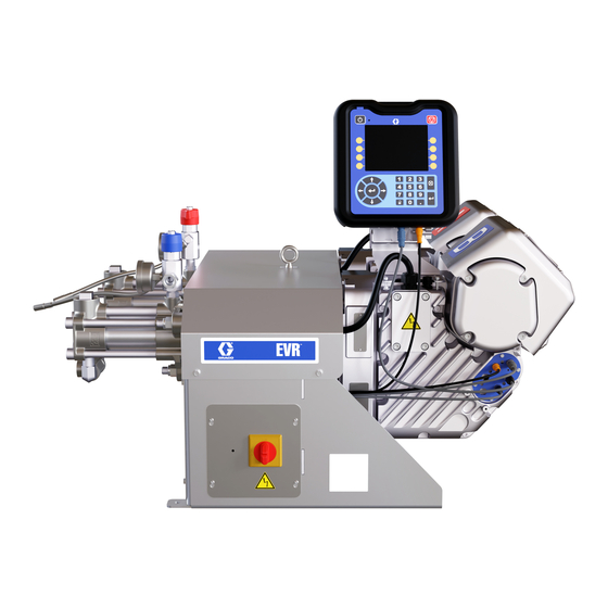
Page 7: Component Identification
AB CAN Distribution Block Electric Driver Required components supplied with the system. Incoming Power Connection EVR systems configured without pumps are pro- Pump Inlets vided with drain/relief valves, which must be Pump Outlets installed after the pumps are assembled, but before Driver Communication and I/O Connectors placing the system into service. -
Page 8: Interior Components
Component Identification Interior Components . 2: Interior Components Key: Power Electronics Cover Ground Lug Communications Gateway Module (CGM) Disconnect Block Terminal Block Connections Circuit Breakers CB-1 (Unit B) CB-2 (Unit A) 3A8565E... -
Page 9: Advanced Display Module (Adm)
Component Identification Advanced Display Module (ADM) User Interface TI12362a1 . 3: ADM Component Identification - Front Buttons Callout Button Function Callout Button Function Soft Defined by application using ADM. System Enables/disables system. When Keys enable/ system is disabled, temperature disable control and dispense operation are Cancel Cancel a selection or number entry... - Page 10 Component Identification ti12363a1 . 4: ADM Component Identification - Rear Key: ADM Module Status LEDs (AN) Conditions AJ Flat Panel Mount AK Model Number AL USB Module Interface Module Status LED AM CAN Cable Connections Signal Description AN Module Status LEDs AP Accessory Cable Connections Green on System is powered up.
-
Page 11: Installation
. 5: Power Cord EVR: grounded through the power cord (customer sup- 2. Remove the four screws to separate the EVR Frame plied). Cover (T) and Power Disconnect Switch (C) from the EVR Frame (S) on the electrical driver. - Page 12 6. Place the power wires into the open area on either side of the Power Disconnect Switch (C) as space permits. 7. Reinstall the EVR Frame Cover (T) and Power Dis- connect Switch (C) using the four screws removed in step 2.
-
Page 13: Install Vented Oil Cap Before Using Equipment
Installation Install Vented Oil Cap Before Using Equipment The driver gear-box is shipped from the factory pre-filled with oil. The temporary unvented cap (PX) prevents oil leaks during shipment. This temporary cap must be replaced with the vented oil cap (PY), supplied with the equipment, before use. -
Page 14: Setup
Setup Setup After placing the EVR in the desired area of operation: NOTE: Make sure the EVR is placed on a level surface. See Dimensions on page 127 for space requirements. Port #6 1. Anchor the EVR to a fixed mounting location. See Dimensions on page 127. -
Page 15: Flushing
Setup Flushing d. Assemble, connect and tighten the component A (Red) inlet hose to the A Pump Inlet (J). 4. Attach the fluid outlet hoses to the Pump Outlets (K). To avoid fire and explosion, always ground equip- ment and waste container. To avoid static sparking and injury from splashing, always flush at the lowest possible pressure. -
Page 16: Operation
NOTE: The EVR is tested with oil at the factory. Flush eyes. To prevent cross-contamination of the equip- out the oil with a compatible solvent before dispensing. -
Page 17: Shutdown
Check your materials for compatibility with zinc plating and sulfur before reusing any material that passed through them, as it may inhibit curing. 1. Press the enable/disable key on the ADM disable the EVR, and verify it is inactive. 3A8565E... -
Page 18: Adjust Material Inlet Pressure
4. Adjust both inlet regulators (if used) so that there is times. Use only enough feed pressure to adequately no air pressure on them and that the regulator pres- feed the EVR pumps. The minimum feed pressure is 70 sure gauge reads zero. psi (0.48 MPa, 4.83 bar). -
Page 19: Maintenance
If oil is low, open ber ports regularly, see dispense valve manual fill cap (FB) and add Graco Part No. 16W645 ISO 220 valve manual silicone-free synthetic EP gear oil. See F . 15. -
Page 20: Change The Oil
2. Turn the Power Disconnect Switch (C) to the OFF ft-lb (25-30 N•m). position. 4. Open the fill cap (FB) and add Graco Part 16W645 3. Perform the Pressure Relief Procedure on page ISO 220 silicone-free synthetic EP gear oil. Check the oil level in the sight glass (FC). -
Page 21: Adm - Battery Replacement And Screen Cleaning
Maintenance ADM - Battery Replacement and 6. Turn the Power Disconnect Switch (C) to the ON position. Screen Cleaning 7. Navigate to Maintenance Screen 1 on the ADM (see page 58). Press to enter Calibration mode. Battery Replacement 8. Press the icon to begin calibration. -
Page 22: Grease Cup Maintenance
Maintenance Grease Cup Maintenance Frequency of greasing intervals is dependent on material being pumped. As a basic schedule, lubricate pump with grease after 250 gallons of product ( five drums of 55 gallon pails) has been passed through the pump. If the grease has become hardened, remove the hardened materials or grease. -
Page 23: Troubleshooting
3. Turn the Power Disconnect Switch (C) OFF. Try the recommended solutions in the order given for NOTE: For Online help, visit http://help.graco.com for each problem, to avoid unnecessary repairs. Also, causes and solutions to each error code. determine that all circuit breakers, switches, and con- trols are properly set and wiring is correct before assuming there is a problem. - Page 24 Troubleshooting Problem Cause Solution Proportioning System 1. Observe gauge to determine which pump is losing pressure. 2. Determine in which direction the Proportioning pump does not hold pump has stalled by observing Pump piston or intake valve leaking pressure when stalled which directional valve indicator light is on.
-
Page 25: Evr Error Codes
Troubleshooting EVR Error Codes Error Code Type Code Description Cause Solution Check heater resistance and A1A_ Alarm Low Current Z_ Fault heat element resistance to ground. Replace fault heater. Check heater resistance and A2A_ Advisory Low Current Z_ Fault heater element resistance to ground. - Page 26 Troubleshooting Error Code Type Code Description Cause Solution A7A_ Fault heater element. Check heater resistance and resistance Unexpected current flow to to ground. Replace heater ele- Alarm Unexpected Current Z_ the heat element ment. Faulty AMZ, Replace AMZ. A8A_ Check fuse on the AMZ that the error element is connected to.
- Page 27 Troubleshooting Error Code Type Code Description Cause Solution Verify CAN cable is plugged in. System unable to Comm. Error _____ Remove and reconnect CAN CAT_ Advisory communicate with tank Tank Stand cable, taking care not to cross stand thread the connector nut. Verify CAN cable is plugged in.
- Page 28 Troubleshooting Error Code Type Code Description Cause Solution Verify CAN cable is plugged into the network. Carefully check for The Gateway lost cross-threaded CAN connections CBGX Alarm Gateway Comm. Error communication with the on the Gateway and AMZ. Yellow Heat Controller DB LED on the Gateway and AMZ board should be flashing.
- Page 29 Troubleshooting Error Code Type Code Description Cause Solution The flow rate requested by Reduce the flow rate so that the Purge Flow Exceeds the purge exceeded the max F4PX Alarm purge flow rate is below the max Max Flow flow rate (26 cycle per flow rate.
- Page 30 Troubleshooting Error Code Type Code Description Cause Solution Inspect for leaks in fluid path. Increase operating pressure by Pressure exceeds increasing flow rate and/or P1D_ Alarm Low Pressure Outlet _ user-defined limit restriction in the hose and valve. Decrease user-defined pressure limit.
- Page 31 Troubleshooting Error Code Type Code Description Cause Solution Inspect for hardened material or obstructions to flow. Attempt to purge material at a reduced flow rate. Pressure exceeds P3F_ Deviation High Pressure Inlet _ Reduce operating pressure by user-defined limit reducing flow rate and/or restric- tion in the hose and valve.
- Page 32 Troubleshooting Error Code Type Code Description Cause Solution First try purging fresh material through the system. Then relieve Dispense line is clogged pressure and check for cured material or obstructions in the dis- pense valve. Adjust orifice restrictions to bal- Orifice restrictions sized Pressure Imbalance ance pressure of A and B materi-...
- Page 33 Troubleshooting Error Code Type Code Description Cause Solution Element continues to raise Defective RTD. Replace. above the setpoint RTD not in correct location See manual to find correct loca- T4A_ Alarm High Temperature Z_ on element tion of RTD on element. Temperature reading has Adjust the temp Offset Error in the risen too high...
- Page 34 Troubleshooting Error Code Type Code Description Cause Solution Verify incoming power is correct Incoming line to line voltage gauge for current draw and verify V2H_ Alarm Low Voltage D_ has dropped below 175V incoming power lines are securely attached to disconnect. For 3 phases with neutral have Incoming line to line voltage V4H_...
-
Page 35: Advanced Display Module (Adm) Operation
Advanced Display Module (ADM) Operation Advanced Display Module (ADM) Operation When main power is turned on by turning the Power Disconnect Switch (C) to the ON position, the splash screen will be displayed until communication and initial- ization is complete. To begin using the ADM, the machine must be on and enabled. -
Page 36: Adm Screen Overview
ADM Screen Overview ADM Screen Overview Home Run Screen System Active Recipe Error and Events Status of State Selected Display Dispense Valve To select a recipe, use the navigation keys to highlight the active recipe bar. Then press the Enter button to open a drop down menu where the desired recipe can be selected. - Page 37 ADM Screen Overview NOTE: When recirculation is installed, the recirculation To initiate a recipe dispense, press the icon to feature is activated, and the recirculation icon enter edit mode on the Home Run Screen, then press will appear on the Home Run Screen. See System Setup Screen 4, page 47, for information on installing icon to start the recipe dispense.
- Page 38 ADM Screen Overview De-Pressurize: Press the de-pressurize icon Purge: Press the purge icon to initiate the purge initiate the de-pressurization feature. When the feature and purge material from the pumps. When the de-pressureize icon is pressed, the icon will turn gray purge icon is pressed, the icon will turn gray , and the system will open the dispense valve, and the system will open the dispense valve and run...
- Page 39 ADM Screen Overview Base Purge: Press the base purge icon to initi- NOTE: The letter in the middle of the icon indi- ate the base purge feature. When the base purge icon cates which pump will be recirculating when the recir- culation icon is pressed.
- Page 40 Tank Stand Status Information 46, the gel timer will display the remaining time before NOTE: The tank stand information and icons will only be shown when the tank stand is connected to the EVR network. the next gel shot under the icon.
-
Page 41: Heat Run Screens
NOTE: The Heat run screens are only visible when the Screens, page 49, for more information on setting up heat box is connected to the EVR network. If an expan- the Heat Idle Timer and Heatsoak Time remaining. sion AMZ is on the network, the Heat Expansion screen will be visible. -
Page 42: Votex Dynamic Mix Valve Run Screen
Voltex run screen. cally initiate heating. If heat does not automatically initi- NOTE: This screen will only be displayed if the Voltex dynamic mix valve is connected to the EVR Network. ate, manually press the icon to turn on the heat. - Page 43 ECAA error will be 3. Motor Ramp Up Time: This changes the amount placed into the events. See EVR Error Codes start- of time in milliseconds the motor takes to get to the ing on page 25 for more information.
-
Page 44: Index Menu
Use the arrow on If the user selects volume (cc) for the shot size, the EVR the ADM directional keypad (AH) to navigate to the rec- will start the dispense when an external trigger or foot switch is pulsed, or the ADM triggers a dispense. -
Page 45: System Setup Screens
ADM Screen Overview System Setup Screens Recipe Definition Screen 2 This screen allows the user to copy , delete On the Index screen, press the icon to navigate , and name selected recipes. Use the to the recipe definition screen. Use the arrow on arrow keys to select a recipe from the list. - Page 46 Enable: Turns on/off the gel timer feature. This screen allows the user to monitor inlet and outlet pressures of the EVR during a dispense. The user can Idle Period: This the amount of time the unit will remain specify a minimum and maximum allowable values for idle before beginning a gel shot dispense.
- Page 47 EVR will begin recirculating the pumps and count down the recirculation on timer. Once the timer has expired, the EVR will count down the recirculation off timer before repeating the process. NOTE: If the recirculation off timer is counting down when a dispense is requested, or when another feature is enabled, the recirculation timer will be stopped.
- Page 48 There are three options available: • Red (A): The EVR will only recirculate with pump A. • Blue (B): The EVR will only recirculate with pump B. • Both: The EVR will recirculate with both pumps.
-
Page 49: Heat Setup Screens
NOTE: The Heat Setup screens will only be visible when the heat box is connected to the EVR network. If an expansion heat module is connected to the network, Heat Setup screens 3, 5, 7, and 9 will be visible. - Page 50 Heat Setup Screen 2 relates to the main heat, and Heat Setup Screen 3 relates to the expansion heat. Heat Setup Screen 3 will only be shown if the expan- sion heat module is connected to the EVR network. NOTE: The icons can be used to request changes to the heat state from the setup screen.
- Page 51 Heat Setup Screen 5 relates to the expansion heat. Heat Setup Screen 5 will only be shown if the expansion heat module is connected to the EVR network. NOTE: The icons can be used to request changes to the heat state from the setup screen.
- Page 52 Heat Setup Screen 6 relates to the main heat, and Heat Setup Screen 7 relates to the expansion heat. Heat Setup Screen 7 will only be shown if the expansion heat module is connected to the EVR net- work. NOTE: The...
- Page 53 Heat Setup Screen 9 relates to the expansion heat. Heat Setup Screen 9 will only be shown if the expansion heat module is connected to the EVR network. NOTE: The icons can be used to request changes to the heat state from the setup screen.
-
Page 54: Voltex Setup Screens
Example: 500ms = half a second to get to the RPM setpoint of 4400RPM. EVR Dispense Wait: This will cause the EVR to wait until the Voltex motor is up to speed before dispensing. 3A8565E... -
Page 55: Tank Stand Setup Screens
NOTE: The Tank Stand Setup Screens are only visible mode. when either the red tank or blue tank is connected to the EVR network. Tank Stand Setup Screen 1 This screen allows the user to define the operating parameters for off-board, integrated tanks. For informa- tion on installing level sensors, refer to the Stainless Steel Tank Stands Instructions-Parts manual. - Page 56 ADM Screen Overview Disabled: Refill Timeout: The refill timeout setting helps protect against over filling the tank when there is a sensor • The tank operation is disabled. failure. The value entered is the time the tank has to fill Monitor: up before timing out.
-
Page 57: Advanced Setup Screens
ADM directional keypad (AH) to navigate to the Click the icon to open a new screen that shows what software is currently installed on the EVR network. Advanced chapter, then use the arrows to scroll through the screens. -
Page 58: Maintenance Setup Screens
If a non-zero number is entered in that field, and the corresponding pump or valve cycles exceeds that value, the EVR will To edit a screen, press the icon. When finished generate and log an advisory informing the user of the condition. -
Page 59: Diagnostics Setup Screens
On the Index screen, press the icon to navigate ules that are connected to the EVR network. As a result, the information displayed on this screen may vary to the Diagnostics screens. Use the arrow on the slightly. - Page 60 ADM Screen Overview The numbers inside the circle in the first column corre- • icon represents the transformer temperature. spond to the connector and zone. The fill color of the See Heat Setup Screen 1, page 49, for instructions circle corresponds to the current heat state of the zone. on how to change the temperature units.
-
Page 61: Shot Log Setup Screens
ADM Screen Overview Shot Log Setup Screens Errors Setup Screens On the Index screen, press the icon to navigate On the Index screen, press the icon to navigate to the Shot Log screens. Use the arrow on the to the Errors/Events screens. Use the arrow on the ADM directional keypad (AH) to navigate to the Shot ADM directional keypad (AH) to navigate to the Errors... -
Page 62: Events Setup Screens
If a box is left unchecked, the EVR will disregard that discrete auto- mation output. For detailed explanations of each inte- gration pin, see I/O Integration on page 68. -
Page 63: Fieldbus Setup Screens
NOTE: The Fieldbus Setup screens are only visible when the Communication Gateway Module (CGM) is connected to the EVR network. Depending on the CGM protocol on the network (Devi- ceNet, EtherNet/IP, ProfiBus, or ProfiNet), the corre-... -
Page 64: Plc Inputs Setup Screens
Inputs chapter, then use the arrows to scroll through the screens. This screen displays the status of the PLC input signals that can be used to troubleshoot when integrating the EVR. PLC Inputs Setup Screen 1 ProfiNet Fieldbus Setup Screen 2 3A8565E... -
Page 65: Plc Outputs Setup Screens
NOTE: The PLC Inputs Setup screens will only be dis- played under the following conditions: • A CGM is present on the EVR network. • The CGM has the corresponding map installed. The PLC Inputs Setup screen displayed is determined by the map installed on the CGM. -
Page 66: Usb Plug-In Screen
Data available for download onto a USB device include shot log data, errors data, and events data. If a heat box is connected to the EVR network, heat data will also be available to download. Press the cancel icon to abort the USB down- load. -
Page 67: Software Update
See the following Icon table. Icon Description Update successful. 4. Insert and press EVR software upgrade token (TK, part no. 19C237) firmly into slot. Update unsuccessful. NOTE: There is no preferred orientation of token. Update complete, no changes necessary. -
Page 68: I/O Integration
24 VDC Digital Output Valve A • 24V is ON • 0V is OFF 24VDC Output 24V for dry contact closure Trigger Trigger Trigger a dispense on the EVR Output System Ready Output Alarm Present Ground/Return Ground Input Recipe Select Integration... -
Page 69: Communications Gateway Module (Cgm)
EVR Heated Map 2006194 2005522 EVR Ambient Map NOTE: If the EVR has a heat box on the network, and control over the heat is desired from the external PLC automation system, it is recommended to use the EVR heated map. -
Page 70: Available Internal Data
NOTE: Print the following tables in color. NOTE: The ambient map is only made up of the EVR signals highlighted in green. The heated map is made up of both the EVR signals highlighted in green, and the heat signals highlighted in yellow. - Page 71 Blue Tank Stand Is Filling Blue Tank Stand Level (0 - Unknown, 1 - Low, 2 - Middle, 3 - High) Voltex Motor Is Running EVR Dispense Waiting for Voltex Motor to Reach Speed Voltex Motor is at Target Speed 3A8565E...
- Page 72 Communications Gateway Module (CGM) EVR Fieldbus Map 2006192 and 2006194 Automation Inputs (signal from EVR to PLC) Minimum Maximum Data Type Byte Description Value Value Additional Info Voltex Air Injection Valve Open ADM Setup Value(s) Changed ADM Counter Value(s) Reset...
- Page 73 Communications Gateway Module (CGM) EVR Fieldbus Map 2006192 and 2006194 Automation Inputs (signal from EVR to PLC) Minimum Maximum Data Type Byte Description Value Value Additional Info 0-15 Red Pump Outlet Pressure 0.00 300.00 XXX.XX bar 32-3 DINT 16-31 Blue Pump Outlet Pressure 0.00...
- Page 74 Communications Gateway Module (CGM) EVR Fieldbus Map 2006192 and 2006194 Automation Inputs (signal from EVR to PLC) Minimum Maximum Data Type Byte Description Value Value Additional Info See Data Exchange DINT 96-9 0-31 Heat - Selected Data Exchange Element Value on page 87 for Min and Max Values.
- Page 75 Communications Gateway Module (CGM) EVR Fieldbus Map 2006192 and 2006194 Automation Inputs (signal from EVR to PLC) Minimum Maximum Data Type Byte Description Value Value Additional Info Heat - Zone 1 Installed Heat - Zone 2 Installed Heat - Zone 3 Installed...
- Page 76 Communications Gateway Module (CGM) EVR Fieldbus Map 2006192 and 2006194 Automation Inputs (signal from EVR to PLC) Minimum Maximum Data Type Byte Description Value Value Additional Info Heat - Zone 1 - Alarm Present Heat - Zone 2 - Alarm Present...
- Page 77 Communications Gateway Module (CGM) EVR Fieldbus Map 2006192 and 2006194 Automation Inputs (signal from EVR to PLC) Minimum Maximum Data Type Byte Description Value Value Additional Info 0-15 Heat - Longest Soak Time Remaining 7200 XXXXX seconds 144- DINT 16-31...
- Page 78 Communications Gateway Module (CGM) EVR Fieldbus Map 2006192 and 2006194 Automation Inputs (signal from EVR to PLC) Minimum Maximum Data Type Byte Description Value Value Additional Info Heat - System Deviation - Reserved Bool 0 Heat - System Deviation - Main AMZ Line Voltage...
- Page 79 Communications Gateway Module (CGM) EVR Fieldbus Map 2006192 and 2006194 Automation Inputs (signal from EVR to PLC) Minimum Maximum Data Type Byte Description Value Value Additional Info 0-15 Heat Zone Multiplexer: * - Setpoint Temperature (XXX deg C) 172- DINT...
- Page 80 Communications Gateway Module (CGM) EVR Fieldbus Map 2006192 and 2006194 Automation Inputs (signal from EVR to PLC) Minimum Maximum Data Type Byte Description Value Value Additional Info 0-15 Heat Zone Multiplexer: * - Deviation - Reserved Bool 0-15 Heat Zone Multiplexer: * - Advisory - Temperature...
-
Page 81: Plc Automation Outputs
NOTE: Print the following tables in color. NOTE: The ambient map is only made up of the EVR signals highlighted in green. The heated map is made up of both the EVR signals highlighted in green, and the heat signals highlighted in yellow. - Page 82 Communications Gateway Module (CGM) EVR Fieldbus Map 2006192 and 2006194 Automation Outputs (signal from PLC to EVR) Data Minimum Maximum Additional Type Byte Description Value Value Information Active Module Errors to Look Up 1 = Red MCM 2 = Blue MCM...
- Page 83 Communications Gateway Module (CGM) EVR Fieldbus Map 2006192 and 2006194 Automation Outputs (signal from PLC to EVR) Data Minimum Maximum Additional Type Byte Description Value Value Information Reserved Bool 0 Reserved Bool 1 System Heat On Request System Heat Off Request...
- Page 84 Communications Gateway Module (CGM) EVR Fieldbus Map 2006192 and 2006194 Automation Outputs (signal from PLC to EVR) Data Minimum Maximum Additional Type Byte Description Value Value Information Update Setpoint Temperature Zone 1 Update Setpoint Temperature Zone 1 Update Setpoint Temperature Zone 3...
- Page 85 Communications Gateway Module (CGM) EVR Fieldbus Map 2006192 and 2006194 Automation Outputs (signal from PLC to EVR) Data Minimum Maximum Additional Type Byte Description Value Value Information Update Setback Temperature Zone 1 Update Setback Temperature Zone 2 Update Setback Temperature Zone 3...
- Page 86 The red box contains data that is required to create a recipe. If set, control of the EVR from the ADM will be completely disabled. ❖ When in operator mode for recipe, the bit must be held high. If the bit is dropped low, the operator mode will be complete, dispensing will stop, and the dispense will be recorded in the shot log.
-
Page 87: Data Exchange
Communications Gateway Module (CGM) Data Exchange NOTE: For EVR Data Exchange timing diagrams, see F . 29 page 108. EVR Fieldbus Map 2006192 and 2006194 Data Exchange Command Value Format and Minimum Maximum Name Read/Write (base 10 decimal) Units Value... - Page 88 Communications Gateway Module (CGM) EVR Fieldbus Map 2006192 and 2006194 Data Exchange Command Value Format and Minimum Maximum Name Read/Write (base 10 decimal) Units Value Value XXXX.XX Recipe Look Up Flowrate Read Only 0.00 200.00 cc/sec Recipe Look Up Calibration X.XX...
- Page 89 Communications Gateway Module (CGM) EVR Fieldbus Map 2006192 and 2006194 Data Exchange Command Value Format and Minimum Maximum Name Read/Write (base 10 decimal) Units Value Value 1 - Low and High Sensor Installed 2 - Low and Mid Sensor Installed...
- Page 90 Communications Gateway Module (CGM) EVR Fieldbus Map 2006192 and 2006194 Data Exchange Command Value Format and Minimum Maximum Name Read/Write (base 10 decimal) Units Value Value Park After Recirculation is Com- 0 - Disable Read/Write pleted Enable 1 - Enabled...
- Page 91 Communications Gateway Module (CGM) EVR Fieldbus Map 2006192 and 2006194 Data Exchange Command Value Format and Minimum Maximum Name Read/Write (base 10 decimal) Units Value Value Dispense Pressure Alerts - Mini- XXX.XX bar Read/Write 0.00 300.00 mum Inlet Red Pump Dispense Pressure Alerts - Mini- XXX.XX bar...
-
Page 92: Heat Data Exchange
Communications Gateway Module (CGM) Heat Data Exchange NOTE: For Heat Data Exchange timing diagrams, see F . 35 page 111. EVR Fieldbus Map 2006192 Heat Data Exchange Command Value Minimum Maximum Name Format and Units Read/Write (base 10 decimal) Value... - Page 93 Communications Gateway Module (CGM) EVR Fieldbus Map 2006192 Heat Data Exchange Command Value Minimum Maximum Name Format and Units Read/Write (base 10 decimal) Value Value System Heat Zone 4 High Tem- XX - Whole Deg C Read/Write perature Deviation Offset...
- Page 94 Communications Gateway Module (CGM) EVR Fieldbus Map 2006192 Heat Data Exchange Command Value Minimum Maximum Name Format and Units Read/Write (base 10 decimal) Value Value System Heat Zone 8 High Tem- XX - Whole Deg C Read/Write perature Alarm Offset...
- Page 95 Communications Gateway Module (CGM) EVR Fieldbus Map 2006192 Heat Data Exchange Command Value Minimum Maximum Name Format and Units Read/Write (base 10 decimal) Value Value 0 = Normal System Heat Zone 12 Heat Rate 1 = Slow Read/Write 2 = Fast...
- Page 96 Communications Gateway Module (CGM) EVR Fieldbus Map 2006192 Heat Data Exchange Command Value Minimum Maximum Name Format and Units Read/Write (base 10 decimal) Value Value System Heat Zone 15 Low Tem- XX - Whole Deg C Read/Write perature Alarm Offset...
-
Page 97: Time And Date
Communications Gateway Module (CGM) Time and Date The following diagram shows the data locations for sending and receiving the date and time across the fieldbus. SYS - Current Date / SYS - Date Request Date Bits 31 30 29 28 27 26 25 24 23 22 21 20 19 18 17 16 15 14 13 12 11 10 Not Used Note 1 Year... -
Page 98: Active Module Error Look-Up Table
MCM Errors To utilize the Active Module Error Look-Up table, the PLC must perform a look-up operation to the EVR. Once the EVR obtains the look-up index, the EVR sys- Alarms Bitfield tem will populate error data into Active Alarm, Devia-... - Page 99 Communications Gateway Module (CGM) NOTE: *_ in the error code will be shown as “A” for the Red Side, or “B” for the Blue Side. Deviation Bitfield Tank Stand Errors Alarm Number Code Alarm Name Inlet Pressure Transducer Dis- P6F_ Deviation Bitfield connected Bit Number Alarm Code...
-
Page 100: Cgm General Timing Diagrams
See I/O Integration on page 68 for location hookup details. Active Module Errors Look Up Automation Inputs (EVR Outputs) Heartbeat To PLC (1Hz) Active Module Errors - Look Up... - Page 101 Communications Gateway Module (CGM) System Parking Request Automation Inputs (EVR Outputs) Heartbeat To PLC (1Hz) System On PLC Lockout is Active System Ready No System Level Alarms are Present No System Level Deviations are Present No System Level Advisories are Present...
- Page 102 Communications Gateway Module (CGM) System Base Purge Request Automation Inputs (EVR Outputs) Heartbeat To PLC (1Hz) System On PLC Lockout is Active System Ready No System Level Alarms are Present No System Level Deviations are Present No System Level Advisories are Present...
- Page 103 Communications Gateway Module (CGM) System Recirculation Request Automation Inputs (EVR Outputs) Heartbeat To PLC (1Hz) System On PLC Lockout is Active System Ready No System Level Alarms are Present No System Level Deviations are Present No System Level Advisories are Present...
- Page 104 Communications Gateway Module (CGM) Operator Recipe Dispense Automation Inputs (EVR Outputs) Heartbeat To PLC (1Hz) System On PLC Lockout is Active System Ready No System Level Alarms are Present No System Level Deviations are Present No System Level Advisories are Present...
- Page 105 Communications Gateway Module (CGM) Start Shot Recipe Dispense Automation Inputs (EVR Outputs) Heartbeat To PLC (1Hz) System On PLC Lockout is Active System Ready No System Level Alarms are Present No System Level Deviations are Present No System Level Advisories are Present...
- Page 106 Communications Gateway Module (CGM) Stop Shot Recipe Dispense Automation Inputs (EVR Outputs) Heartbeat To PLC (1Hz) System On PLC Lockout is Active System Ready No System Level Alarms are Present No System Level Deviations are Present No System Level Advisories are Present...
- Page 107 Communications Gateway Module (CGM) Voltex Operator Recipe Dispense Automation Inputs (EVR Outputs) Heartbeat To PLC (1Hz) System On PLC Lockout is Active System Ready No System Level Alarms are Present No System Level Deviations are Present No System Level Advisories are Present...
- Page 108 Communications Gateway Module (CGM) Voltex Shot Recipe Dispense Automation Inputs (EVR Outputs) Heartbeat To PLC (1Hz) System On PLC Lockout is Active System Ready No System Level Alarms are Present No System Level Deviations are Present No System Level Advisories are Present...
- Page 109 Communications Gateway Module (CGM) Heat Overall CGM Timing Automation Inputs (Heat Outputs) Heat - Heartbeat To PLC (1Hz) PLC Lockout is Active Automation Outputs (Heat Inputs) PLC Lockout Request Other Heat Automation Outputs Data Notes: Automation Outputs Data needs to have the " PLC Lockout Request"...
- Page 110 Communications Gateway Module (CGM) . 33: Heat System Ack-Clear Errors Automation Inputs (Heat Outputs) Heat - Heartbeat To PLC (1Hz) Once System Heat Acknowledge / Heat - System Alarms (integer/bitfield) Clear Errors Bit has been sent, the system automatically tries Heat - No System Level Alarms Present to clear the active Errors.
- Page 111 Process needs to be repeated for deviations and advisories before sending the System Heat Acknowledge / Clear Errors Bit . 35: Heat Data Exchange Timing Automation Inputs (EVR Outputs) Heat - Heartbeat To PLC (1Hz) Desired Data PLC Lockout is Active...
-
Page 112: Connection Details
Communications Gateway Module (CGM) Connection Details Module Status (MS) State Description Comments Fieldbus Not initialized No power or module in Connect cables to the fieldbus per fieldbus standards. “SETUP” or “NW_INIT” state PROFINET Green Normal Diagnostic event(s) operation present Flashing Initialized, Used by engineering Green... - Page 113 Communications Gateway Module (CGM) EtherNet/IP DeviceNet Link 3 4 5 TI11814A TI11815A The EtherNet interface operates at 100Mbit, full duplex, as required by PROFINET. The EtherNet interface is Network Status (NS) auto-polarity sensing and auto-crossover capable. State Description Network Status (NS) Not online / No power State Description...
- Page 114 Communications Gateway Module (CGM) PROFIBUS 9 8 7 6 TI11816A Operation Mode (OP) State Description Not online / No power Green On-line, data exchange Flashing On-line, clear Green Flashing Red Parameterization error (1 flash) Flashing Red PROFIBUS Configuration error (2 flashes) Status Mode (ST) State Description...
-
Page 115: Appendix A - Obsoleted Evr Maps
Appendix A - Obsoleted EVR Maps Appendix A - Obsoleted EVR Maps With the addition of heat to the EVR, the 19C930 map is Gateway Map: EVR Fieldbus Map 19C930 now obsolete and will no longer be shipped with EVR systems. - Page 116 Appendix A - Obsoleted EVR Maps EVR Fieldbus Map 19C930 Automation Inputs (signal from EVR to PLC) Minimum Maximum Tag ID Description Data Type Value Value Byte Gel Shot is Dispensing Boolean Gel Shot Countdown Timer is Alarming Boolean Red Tank is Filling...
- Page 117 Appendix A - Obsoleted EVR Maps EVR Fieldbus Map 19C930 Automation Inputs (signal from EVR to PLC) Minimum Maximum Tag ID Description Data Type Value Value Byte System Ratio Offset (-/+ X.XX) sint16 0.00 0.25 0-14 22-23 Active Recipe Flowrate (XXXX.XX uint16 69.33...
-
Page 118: Plc Outputs
Appendix A - Obsoleted EVR Maps PLC Outputs EVR Fieldbus Map 19C930 Automation Outputs (signal from PLC to EVR) Minimum Maximum Tag ID Description Data Type Value Value Byte System Enable Request Boolean PLC Lockout Request * Boolean Operator Dispense/ Shot... - Page 119 Min and Max Values NOTES: If set, control of the EVR from the ADM will be disabled. When in operator mode for recipe, the bit must be held high, if dropped low the operator mode will be completed, dispensing will stop and the dispense will be recorded into the shot log.
-
Page 120: Recycling And Disposal
Recycling and Disposal Recycling and Disposal End of Product Life At the end of a product’s useful life, recycle it in a responsible manner. At the end of the product’s useful life, dismantle and recycle it in a responsible manner. •... -
Page 121: Schematics
Schematics Schematics 3A8565E... - Page 122 Schematics BROWN BLUE BROWN BLUE 3A8565E...
- Page 123 Schematics 3A8565E...
- Page 124 Schematics 3A8565E...
- Page 125 Schematics 3A8565E...
- Page 126 Schematics 3A8565E...
-
Page 127: Dimensions
Dimensions Dimensions 240VAC Single Phase Dimensions A Machine Mounting Holes 20.1 in. (51 cm) For 3/8 in. (10mm) Mounting Fasteners B Machine Mounting Holes 26.7 in. (68 cm) C Total Machine Height 31 in. (79 cm) D Total Machine Length 40.3 in. - Page 128 Dimensions 480VAC Three Phase Dimensions A Machine Mounting Holes 20.1 in. (51 cm) For 3/8 in. (10mm) Mounting Fasteners B Machine Mounting Holes 26.7 in. (68 cm) C Total Machine Height 41 in. (79 cm) D Total Machine Length 40.3 in. (102 cm) E Total Machine Width 30.5 in.
-
Page 129: Technical Specifications
Technical Specifications Technical Specifications Metric Maximum fluid working pressure ‡ 3500 psi 24 MPa, 241 bar Maximum fluid temperature 120°F 50°C Fluid circulation ports 1/4 NPS(m) 200-240V, 1ph, 41A, 50/60 Hz Line voltage rating 480V, 3ph, 18A, 50/60Hz Stainless steel, zinc-plated carbon steel, brass, tungsten Wetted parts carbide, chrome, fluoroelastomer, PTFE, ultra-high molec- ular weight polyethylene, silicon nitride... -
Page 130: Graco Standard Warranty
With the exception of any special, extended, or limited warranty published by Graco, Graco will, for a period of twelve months from the date of sale, repair or replace any part of the equipment determined by Graco to be defective.
Need help?
Do you have a question about the EVR and is the answer not in the manual?
Questions and answers