Table of Contents
Advertisement
Operation, Repair, and Parts
EcoQuip
EcoQuip Vapor
EcoQuip
Blast System
System
Blast
Blast
System
Vapor abrasive
abrasive blast
blast system.
Vapor
Vapor
abrasive
blast
or or or hazardous
hazardous locations.
locations.
hazardous
locations.
Important Safety
Safety Instructions
Important
Important
Safety
Read all warnings and instructions in this manual. Save these
instructions.
125 psi
125
125
psi (8.6
psi
(8.6 bar,
(8.6
bar, 0.86
bar,
0.86 MPa)
0.86
Working Pressure
Working
Working
Pressure
Pressure
See page
page 2 2 2 for
for Model
Model information.
See
See
page
for
Model
Vapor Abrasive
Vapor
system. For
For professional
professional use
system.
For
professional
Instructions
Instructions
MPa) Maximum
MPa)
Maximum
Maximum
information.
information.
PROVEN QUALITY. LEADING TECHNOLOGY.
Abrasive
Abrasive
use only.
only. Not
Not approved
approved for
use
only.
Not
approved
334666C
for use
use in in in explosive
explosive atmospheres
atmospheres
for
use
explosive
EN
atmospheres
Advertisement
Table of Contents
Troubleshooting

Related Manuals for Graco EcoQuip EQ200T


Summary of Contents for Graco EcoQuip EQ200T
- Page 1 Operation, Repair, and Parts EcoQuip EcoQuip Vapor EcoQuip Vapor Vapor Abrasive Abrasive Abrasive Blast System System Blast Blast System 334666C Vapor abrasive abrasive blast blast system. system. For For professional professional use use only. only. Not Not approved approved for for use use in in in explosive explosive atmospheres...
-
Page 2: Table Of Contents
Troubleshooting..........22 Dimensions ............48 Troubleshooting Examples ......25 Technical Specifications........50 Repair..............27 Repairing the Main Air Regulator ....27 Graco Extended Warranty for EcoQuip™ Flushing the Diaphragm Valve ...... 28 Components ......... 52 Models Related Manuals Manuals Models... -
Page 3: Warnings
Warnings Warnings Warnings Warnings The following warnings are for the setup, use, grounding, maintenance, and repair of this equipment. The exclamation point symbol alerts you to a general warning and the hazard symbols refer to procedure-specific risks. When these symbols appear in the body of this manual or on warning labels, refer back to these Warnings. - Page 4 Warnings WARNING WARNING WARNING BURN BURN BURN HAZARD HAZARD HAZARD Equipment surfaces and fluid that is heated can become very hot during operation. To avoid severe burns: • Do not touch hot fluid or equipment. FIRE FIRE FIRE AND AND EXPLOSION EXPLOSION HAZARD EXPLOSION HAZARD...
-
Page 5: Notes
Notes Notes Notes Notes 334666C... -
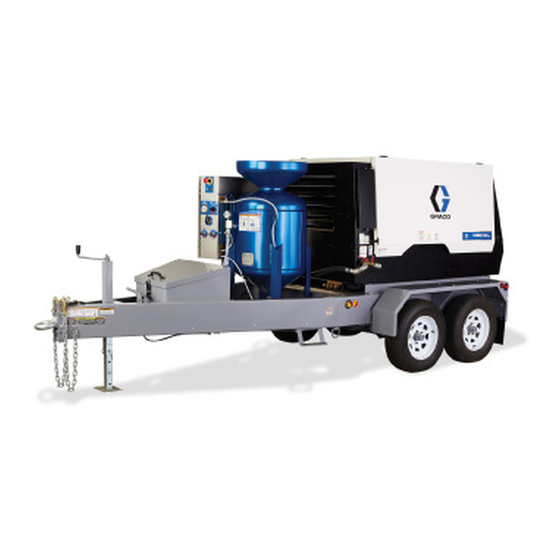
Page 6: System Component Identification
System Component Identification System Component Component Identification Identification System System Component Identification EQ200T and and EQ400T EQ400T EQ200T EQ200T EQ400T 334666C... -
Page 7: Datatrak Controls
System Component Identification Key: Key: Key: Key: Key: Key: Blast Control Switch Blast Air Pressure Gauge Blast Nozzle Selector Valve Blast Hose Rinse Ball Valve Air Supply Connection Pop-Up Pin Blast Connection Pot Dump Valve Pneumatic Control Connection Auto Vent Valve Electric Control Connection Blast Check Valve Supply Air Pressure Gauge... -
Page 8: Pressure Relief Procedure
Pressure Relief Procedure Pressure Relief Relief Procedure Procedure Pressure Pressure Relief Procedure 2. Close the abrasive ball valve. 3. Turn the compressor off. Close the compressor Follow the Pressure Relief Procedure supply air valve. whenever you see this symbol. 4. Engage the blast control switch to relieve pressure in the system. -
Page 9: Operation
Operation Operation Operation Operation Checklist Before Before Starting Starting Checklist Checklist Before Starting be used with hose lengths less than 150 ft (45 m). Blasting with 150 ft (45 m) or more of blast hose requires the use of an electric blast control switch. •... -
Page 10: Hose
Operation Connecting the the Blast Blast Hose Hose and and Air Connecting Connecting Blast Hose 3. Connect the blast hose, hose restraints, control Hose hoses, and coupler pins. Hose Hose 1. Make sure the inlet hose connections are tight, and that hose restraints are properly installed and secure. -
Page 11: Setting Up The Equipment
Operation Setting Up Up the the Equipment Equipment Setting Setting Equipment 2. Flush water through the pot and out of the disconnected abrasive ball valve before filling the pot with water and abrasive. 1. Disconnect the abrasive hose at the cam and groove with the abrasive ball valve closed. - Page 12 Operation 8. Disengage the Emergency Stop. 10. Add 10 gallons (30 liters) of fresh water to the pot. Wear appropriate personal protective equipment, including an appropriately fit-tested government approved respirator suitable for the dust conditions. Add abrasive material (minimum four bags, maximum ten 50 lb (23 kg) bags of high-mass abrasive, or eight 50 lb (23 kg) bags of low mass abrasive).
- Page 13 Operation NOTE: It 13. Turn the selector valve to FILL. 14. Wait for pot pressure to increase. NOTE: NOTE: can take up to several minutes for the pot to pressurize. NOTE: NOTE: NOTE: The water pump should begin cycling. If ti24824a not, open the pot pressure regulator enough to NOTE: The pop-up cannot be pushed down...
- Page 14 Operation 19. Open the abrasive ball valve. 21. Slowly adjust the abrasive metering valve while the abrasive is blasting from the nozzle. Typical adjustment ranges from 1/8 to 1/4 turn open. NOTE: The DataTrak can be used to assist in NOTE: NOTE: setting the pump cycle rate.
-
Page 15: Blasting Tips
Operation Blasting Tips Tips Blasting Blasting Tips Blasting Blasting on Blasting on Higher Higher Surfaces Higher Surfaces Surfaces When blasting on a surface higher than the When first learning the effects of the blaster, get a equipment, make sure that there is a length of blast better understanding of the results by starting at a hose on the ground equal to 10-20% of the height. - Page 16 Operation Abrasive Abrasive Abrasive Metering Metering Metering Valve Valve Settings Valve Settings Settings There is no fixed formula for what works best in each application. The information below works best for the majority of the time. From this initial setting, adjustments can be made up or down to get the fastest removal rates without damage to the surface.
-
Page 17: Using The Wash Feature
Operation Using the the Wash Wash Feature Feature Using Using Wash Feature 2. Turn the selector valve to WASH. The wash feature causes air-driven water (without abrasive) to rinse areas that have already been blasted with abrasive. It is also a convenient feature for flushing abrasive from the blast hose. -
Page 18: Refilling The Pot With Abrasive
Operation Refilling the the Pot Pot with with Abrasive Abrasive Refilling Refilling with Abrasive 4. After all of the pressure in the pot has been relieved, engage the pop-up pin by compressing the spring and turning the handle 90° to hold the pop-up in the open position. -
Page 19: Shutting Down
Operation Shutting Down Down Shutting Shutting Down 5. Hold a bucket under the cam-lock coupler, then turn the selector valve to WASH. This will clean debris from the cam-lock coupler and gasket. NOTE: NOTE: NOTE: Make sure the gasket is clean and in place after the procedure. - Page 20 Operation 8. Engage the pop-up pin to hold the pop-up open 10. Close the pop-up and connect the abrasive hose. and allow air to enter. 9. Open the abrasive ball valve and flush the pot of any remaining abrasive material. NOTE: The system must be winterized if it will be NOTE: NOTE:...
-
Page 21: Winterizing The Equipment
Operation Winterizing the the Equipment Equipment Winterizing Winterizing Equipment 5. Turn the selector valve to RINSE and open the rinse ball-valve. While holding the rinse hose over the pot, run the pump until windshield wash Vapor-Abrasive Blasters must be winterized comes out of the rinse hose. -
Page 22: Troubleshooting
Troubleshooting Troubleshooting Troubleshooting Troubleshooting Problem Cause Solution Problem Problem Cause Cause Solution Solution The pot will not properly The air supply is inadequate. Make sure the air inlet pressure gauge reads pressurize. 100-125 psi (6.8–8.6 bar, 0.68–0.86 MPa). If the gauge does not read 100–125 psi, check the air compressor for proper setup. - Page 23 Troubleshooting Problem Cause Solution Problem Problem Cause Cause Solution Solution No abrasive flows from The pot does not have a Refilling the Pot with Abrasive, page the nozzle during blast sufficient amount of abrasive. mode. The system is not properly set Setting Up the Equipment, page Make sure the pot pressure is properly set.
- Page 24 Troubleshooting Problem Cause Solution Problem Problem Cause Cause Solution Solution The blast control is not The main air regulator is stuck Repairing the Main Air Regulator, page engaged but blasting still open. occurs. The blast control tubing is not Ensure air tubing is routed and connected connected properly.
-
Page 25: Troubleshooting Examples
Troubleshooting Troubleshooting Examples Examples Troubleshooting Troubleshooting Examples 3. Make sure the pop-up is engaged with its gasket. Turn the selector valve to WASH, then open the abrasive ball valve to pressurize the pot. Set the Checking Checking Checking for for Leaks Leaks Leaks pot pressure to 145 psi (9.9 Bar, 0.99 MPa). - Page 26 Troubleshooting Pneumatic Pneumatic Pneumatic Blast Blast Blast Control Control Control Circuit Circuit Circuit 4. If the previous steps do not fix the issue, replace the air relay. 1. At the Air-Relay, disconnect the push-to-connect tubing and check the trigger circuit (from the blast control handle).
-
Page 27: Repair
Repair Repair Repair Repair Repairing the the Main Main Air Air Regulator Regulator Repairing Repairing Main Regulator 4. Remove the diaphragm cover for access to the diaphragm and to the end of the piston shaft. EQ200 Common Spare Parts, page 47 for repair kits. -
Page 28: Flushing The Diaphragm Valve
Repair Flushing the the Diaphragm Diaphragm Valve Valve Flushing Flushing Diaphragm Valve 3. Disconnect the quick coupling at the abrasive ball valve (not at the bottom of the pot). This procedure can be performed with the component still mounted in the panel. If large-grit abrasive or other foreign matter becomes lodged in the diaphragm valve, it will become necessary to flush the valve. -
Page 29: Repairing The Diaphragm Valve
Repair Repairing the the Diaphragm Diaphragm Valve Valve Repairing Repairing Diaphragm Valve 4. Replace the diaphragm (natural rubber compound) and hand-tighten it (only as far as necessary) to establish the alignment with the canister. NOTE: NOTE: NOTE: There are one or two shims between the diaphragm and the actuator. -
Page 30: Cleaning The Auto-Vent Valve
Repair Cleaning the the Auto Auto - - - Vent Vent Valve Valve Cleaning Cleaning Auto Vent Valve 4. Use the rinse hose to force water backwards into the valve stem. After the pop-up has been closed while filling the pot, the auto-vent valve should release air (you should be able to hear the air venting). -
Page 31: Replacing The Datatrak Battery
HAZARD To reduce the risk of fire and explosion, the battery must be replaced in a non-hazardous location. Use only an approved replacement battery (see table). Use of an unapproved battery will void Graco’s warranty. Replace Battery Battery Replace Replace Battery 1. -
Page 32: Replacing The Datatrak Fuse
EXPLOSION HAZARD To reduce the risk of fire and explosion, the fuse must be replaced in a non-hazardous location. Use only an approved replacement fuse (see table). Use of an unapproved fuse will void Graco’s warranty. Replace Fuse Fuse Replace... -
Page 33: Notes
Notes Notes Notes Notes 334666C... -
Page 34: Parts
Parts Parts Parts Parts EQ200T and and EQ400T EQ400T EQ200T EQ200T EQ400T Apply anti-seize to studs. Torque to 25–30 ft-lb (34–40 N•m). 334666C... - Page 35 Parts EQ200T EQ200T EQ200T and and EQ400T EQ400T EQ400T Parts Parts Parts List List List Ref. Ref. Ref. Part Part Part Description Description Description Qty. Qty. Qty. Ref. Ref. Ref. Part Part Part Description Description Description Qty. Qty. Qty. – – – – – PRESSURE POT, 6.5 EQ1840 HOSE, braided, clear,...
-
Page 36: Enclosure
Parts Enclosure Enclosure Enclosure Torque fitting to 35 – 40 ft-lb (47 – 54 N•m). 334666C... - Page 37 Parts Enclosure Enclosure Enclosure Parts Parts Parts List List List Ref. Ref. Ref. Part Part Part Description Description Description Qty. Qty. Qty. Ref. Ref. Part Ref. Part Part Description Description Description Qty. Qty. Qty. – – – – – ENCLOSURE, ss, el, 30 in. x 24 111831 SCREW, cap, skt, button hd in.
-
Page 38: Trailers
Parts Trailers Trailers Trailers EQ200 Trailers Trailers EQ200 EQ200 Trailers EQ200 EQ200 EQ200 Parts Parts Parts List List List Ref. Ref. Part Ref. Part Part Description Description Description Qty. Qty. Qty. Ref. Ref. Ref. Part Part Part Description Description Description Qty. - Page 39 Parts EQ4E03 Trailer Trailer EQ4E03 EQ4E03 Trailer EQ4E03 EQ4E03 Parts EQ4E03 Parts List Parts List List Ref. Part Part Description Qty. Ref. Part Part Description Qty. Ref. Ref. Part Description Description Qty. Qty. Ref. Ref. Part Description Description Qty. Qty. –...
- Page 40 Parts EQ4E04 Trailer Trailer EQ4E04 EQ4E04 Trailer EQ4E04 EQ4E04 EQ4E04 Parts Parts Parts List List List Ref. Ref. Part Ref. Part Part Description Description Description Qty. Qty. Qty. Ref. Ref. Ref. Part Part Part Description Description Description Qty. Qty. Qty. –...
-
Page 41: Pressure Pot
Parts Pressure Pot Pressure Pressure Pressure Pot Pot Parts Parts List List Pressure Pressure Parts List Ref. Ref. Ref. Part Part Part Description Description Description Qty. Qty. Qty. Ref. Ref. Ref. Part Part Part Description Description Description Qty. Qty. Qty. 25A057 PRESSURE POT, 17D790... -
Page 42: Hose Schematic
Hose Schematic Hose Schematic Schematic Hose Hose Schematic Part Part Ref. Ref. Part Ref. Part Color, Color, Color, Tube Tube Tube Size Size Size Ref. Ref. Ref. Part Part Color, Color, Tube Color, Tube Size Tube Size Size Length Length Length Length Length... -
Page 43: Vapor Abrasive Blast Systems And Accessories
Vapor Abrasive Blast Systems and Accessories Vapor Abrasive Abrasive Blast Blast Vapor Vapor Abrasive Blast Systems Systems Systems and and Accessories Accessories Accessories EcoQuip EcoQuip EcoQuip System System Configurator System Configurator Configurator Model Model Model Series Series Series Trailer Trailer Option Trailer Option Option... -
Page 44: Model Series
Vapor Abrasive Blast Systems and Accessories Model Series Series Model Model Series Part Description Part Part Description Description 100 Series Series Series Bare package, mobile unit EQ100M EQ10EM Complete package, electric blast control, mobile unit EQ10PM Complete package, pneumatic blast control, mobile unit EQ10XM Complete package, pneumatic blast control, ATEX approved, mobile unit 300 Series... -
Page 45: Hoses
Vapor Abrasive Blast Systems and Accessories Hoses Hoses Hoses Part Part Part ID ID ID Blast Blast Blast Coupler 1 1 1 Coupler 2 2 2 Length Length Length Models Models Models Notes Notes Notes Coupler Coupler Coupler Coupler Control Control Control EQ5237 1.0 in. -
Page 46: Blast Control Hoses/Cables
Vapor Abrasive Blast Systems and Accessories Blast Control Control Hoses/Cables Hoses/Cables Blast Blast Control Hoses/Cables Part Description Part Part Description Description 17F501 Blast control hose, pneumatic twinline, 55 ft 24X746 Blast control hose, pneumatic twinline, 55 ft, ATEX approved 17F502 Blast control hose, pneumatic twinline, 55 ft, extension 24X744 Blast control hose, pneumatic twinline, 55 ft. -
Page 47: Common Spare Parts
Vapor Abrasive Blast Systems and Accessories Common Spare Spare Parts Parts Common Common Spare Parts Part Description Part Part Description Description 17B186 Pump repair kit Blast hose coupler gasket, nylon couplers 17C459 17C124 Blast hose coupler gasket, brass couplers 17C125 Gasket, abrasive ball valve cam-lock —... -
Page 48: Dimensions
Dimensions Dimensions Dimensions Dimensions EQ200 Trailers Trailers EQ200 EQ200 Trailers Electronic Brakes Hydraulic Brakes EQ4E03 EQ4E03 EQ4E03 334666C... - Page 49 Dimensions EQ4E04 EQ4E04 EQ4E04 334666C...
-
Page 50: Technical Specifications
Technical Specifications Technical Specifications Specifications Technical Technical Specifications EQ200T U.S. Metric EQ200T EQ200T U.S. U.S. Metric Metric Maximum Working Pressure 125 psi 8.6 bar, 0.86 MPa Operating Temperature 35° – 110° F 1.6° – 43.3° C Blast Hose Size 1 in. ID 25.4 mm ID Abrasive Capacity 400 –... - Page 51 Technical Specifications EQ400T EQ400T EQ400T U.S. U.S. U.S. Metric Metric Metric Maximum Working Pressure 125 psi 8.6 bar, 0.86 MPa Operating Temperature 35° – 110° F 1.6° – 43.3° C Blast Hose Size 1.25 in. ID 31.75 mm ID Abrasive Capacity 400 –...
-
Page 52: Components
EcoQuip name to be free from defects in material and workmanship on the date of sale to the original purchaser for use. Graco will, for three (3) years from the date of sale, repair or replace any part of the equipment determined by Graco to be defective.
Need help?
Do you have a question about the EcoQuip EQ200T and is the answer not in the manual?
Questions and answers