Table of Contents
Advertisement
Quick Links
Advertisement
Table of Contents

Subscribe to Our Youtube Channel
Related Manuals for HIKVISION DS-B30 Series


Summary of Contents for HIKVISION DS-B30 Series
- Page 1 Multi-Functional Video Center Quick Start Guide...
- Page 2 Document, which may include licenses obtained from third parties. ● Any part of the Document, including text, pictures, graphics, etc., belongs to Hikvision. No part of this Document may be excerpted, copied, translated, or modified in whole or in part by any means without written permission.
- Page 3 Multi-Functional Video Center • Quick Start Guide HIKVISION SHALL NOT TAKE ANY RESPONSIBILITIES FOR ABNORMAL OPERATION, PRIVACY LEAKAGE OR OTHER DAMAGES RESULTING FROM CYBER-ATTACK, HACKER ATTACK, VIRUS INFECTION, OR OTHER INTERNET SECURITY RISKS; HOWEVER, HIKVISION WILL PROVIDE TIMELY TECHNICAL SUPPORT IF REQUIRED.
- Page 4 Multi-Functional Video Center • Quick Start Guide Preface Applicable Models This manual is applicable to the DS-B30 series multi-functional video center. Default Parameters Type Default Parameter Device Login user name: admin IP address: 192.0.0.64 SSH connection To improve system security, it is highly recommended to change password regularly. In order to protect your privacy and corporate data and avoid network security issues, it is recommended to set strong password that meets security requirements.
- Page 5 Multi-Functional Video Center • Quick Start Guide Safety Instructions The device must be connected to an earthed mains socket-outlet. The socket-outlet shall be installed near the device and shall be easily accessible. Do not touch the bare components (such as the metal contacts of the inlets) and wait for at least 5 minutes, since electricity may still exist after the device is powered off.
- Page 6 Multi-Functional Video Center • Quick Start Guide Make sure that the power has been disconnected before you wire, install, or disassemble the device. If smoke, odor, or noise arises from the device, immediately turn off the power, unplug the power cable, and contact the service center.
-
Page 7: Table Of Contents
Multi-Functional Video Center • Quick Start Guide TABLE OF CONTENTS Chapter 1 Introduction ....................... 1 Overview ................................1 Packing List................................1 Appearance ................................2 1.3.1 Host System ............................... 2 1.3.2 Service Board ............................. 6 Chapter 2 Installation ....................... 12 Safety Precautions .............................. 12 Install a Board .............................. -
Page 8: Chapter 1 Introduction
Multi-Functional Video Center • Quick Start Guide Chapter 1 Introduction Overview Designed with reference to the Advanced Telecommunications Computing Architecture (ATCA), the Multi-Functional Video Center (hereinafter referred to as the MVC or the device) supports matrix switching of analog and digital videos, video encoding and decoding, and network real-time preview. -
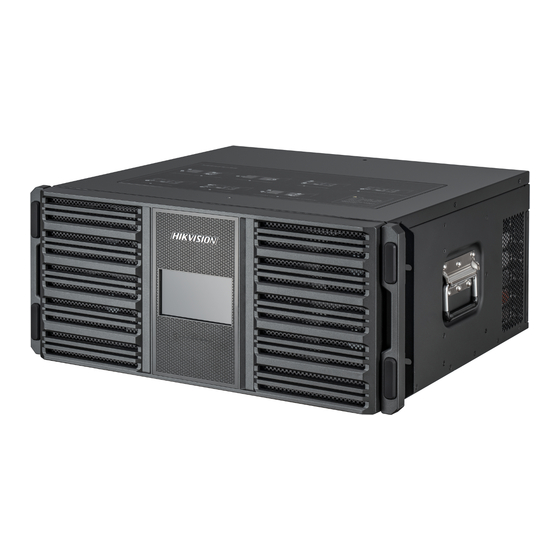
Page 9: Appearance
Multi-Functional Video Center • Quick Start Guide Item Quantity Packed Item Quantity Packed DB-9 to RJ-45 cable Appearance The front view of the chassis. Front View of 8 U MVC Chassis... - Page 10 Multi-Functional Video Center • Quick Start Guide Front View of 4.5 U MVC Chassis The back view of the chassis. Back View of 8 U MVC Chassis...
- Page 11 Multi-Functional Video Center • Quick Start Guide Name Description Power supply slot (POWER 1) Supports the power supply. Power supply slot (POWER 2) Supports the power supply. Main control board slot (M1) Supports the main control board. Main control board slot (M2) Supports the main control board.
- Page 12 Multi-Functional Video Center • Quick Start Guide For an MVC with only one main control board, install the main control board in slot M1. For an MVC with two main control boards, install them in slots M1 and M2. Main Control Board Front View of Main Control Board Name Description...
-
Page 13: Service Board
Multi-Functional Video Center • Quick Start Guide Network Board Network Board Front View Name Description PWR LED Steady green: the board is powered on normally. ACT LED Flashing green: the board runs normally. Two 10/100/1000 Mbps self-adaptive network ports, which can be Network port used to connect to the network ports of a switch. - Page 14 Multi-Functional Video Center • Quick Start Guide No. Name Description PWR LED Steady green: the board is powered on normally. Support 4 channels of HDMI video input, up to 1920 × 1200 P60 frame Video input port (HDMI IN) access and encoding, and embedded audio input. ACT LED Flashing green: the board runs normally.
- Page 15 Multi-Functional Video Center • Quick Start Guide DVI Input Board DVI Input Board Front View No. Name Description PWR LED Steady green: the board is powered on normally. Video input port Support 4 channels of DVI video input and each channel resolution of (DVI IN) up to 1920 ×...
- Page 16 Multi-Functional Video Center • Quick Start Guide No. Name Description ACT LED Flashing green: the board runs normally. Provide a mini-DP 4-in-1 line-in audio input port. Use an external audio Audio input port adapter cable to connect to this port for audio input. When the DP input board is connected to a 4K@60 Hz video signal source, only one channel can be connected.
- Page 17 Multi-Functional Video Center • Quick Start Guide HDMI Output Board HDMI Output Board Front View No. Name Description PWR LED Steady green: the board is powered on normally. Video output port Support 4 channels of HDMI video output and embedded audio (HDMI OUT) output.
- Page 18 Multi-Functional Video Center • Quick Start Guide VGA Output Board VGA Output Board Front View No. Name Description PWR LED Steady green: the board is powered on normally. Video output port Support 4 channels of VGA video output. (VGA OUT) ACT LED Flashing green: the board runs normally.
-
Page 19: Chapter 2 Installation
Multi-Functional Video Center • Quick Start Guide Chapter 2 Installation Safety Precautions The MVC is a highly sophisticated and system-level electronic device, so it is recommended to use professionals to install and maintain the MVC. To avoid personal and property injury, please read the safety precautions in this section carefully before installation. -
Page 20: Install A Board
Multi-Functional Video Center • Quick Start Guide Anti-Interference Requirements The on-site power supply system must have effective measures to prevent grid interference. Do not use the working ground together with the grounding device or lightning protection grounding device of the power equipment, and keep the two as far away as possible. ... - Page 21 Multi-Functional Video Center • Quick Start Guide Remove the Baffle Do not remove the baffle from the empty slot to avoid affecting the ventilation. Insert a service board (2) into the slot.
- Page 22 Multi-Functional Video Center • Quick Start Guide Insert a Service Board Push the service board to the bottom. Use a screwdriver to tighten the screws on both sides. Secure the Service Board to the Slot...
-
Page 23: Install The Mvc In The Rack
Multi-Functional Video Center • Quick Start Guide Install the MVC in the Rack The front weight and rear weight of the MVC are inconsistent. Lift the MVC with cautious. Verify that the rack is reliably grounded and is stable. Install a rack bracket on an empty slot of the rack and secure the rack bracket by screws. Make sure the rack bracket can support the MVC. -
Page 24: Connect Cables
Multi-Functional Video Center • Quick Start Guide Rack Mount the 4.5 U MVC Make reliable grounding between the grounding terminal of the MVC and the rack. The grounding point is located on the rear of the MVC. See “2.4.1 Connect the Grounding Cable ” for details. - Page 25 Multi-Functional Video Center • Quick Start Guide The MVC must be grounded to ensure the personal safety and device safety. With Grounding Row Connect one end of the grounding cable (2) to the grounding terminal of the grounding row (3) in the equipment room. Connect the other end of the grounding cable to an MVC grounding terminal (1) and tighten the screw.
-
Page 26: Connect The Audio And Video Cables
Multi-Functional Video Center • Quick Start Guide Connect the Grounding Cable to the Ground The video cables are user supplied and you need to purchase them by yourself. The audio cables are shipped with the MVC. Connect the audio and video cables to the MVC. Audio and Video Cables Service Board Audio and Video Cables... -
Page 27: Connect The Network Cable
Multi-Functional Video Center • Quick Start Guide Connect the main control board (3) and network board (1) to the switch (2), respectively. It is recommended to use CAT 6 Ethernet cables for connection. Connect the network board to the switch: ... -
Page 28: Connect The Power Cord
Multi-Functional Video Center • Quick Start Guide The MVC uses 2 power supplies for redundancy. The power supply socket locates near the fan (1). Use two power cords to connect two power supply sockets (2) to the power supply in the equipment room, thus the MVC is powered on. -
Page 29: Chapter 3 Get More Information
Multi-Functional Video Center • Quick Start Guide Chapter 3 Get More Information Scan the QR code below to view the user manual. The following operations require network data traffic and are recommended to be performed in a Wi-Fi environment. User Manual... - Page 30 UD35747B-E...
Need help?
Do you have a question about the DS-B30 Series and is the answer not in the manual?
Questions and answers