Table of Contents
Advertisement
Quick Links
Model #
HDFP48-57E
OMSID # 320084801
#
HDFP48-57AE
# 320084798
ASSEMBLY INSTRUCTIONS
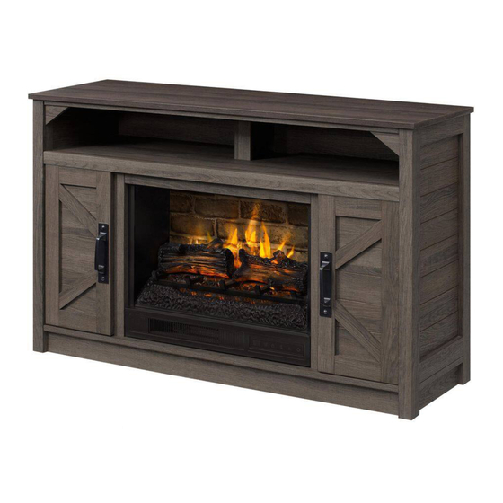
Pine Creek 48" Coil Media Electric Fireplace
Questions, problems, missing parts?
Before returning to the store, call Customer Service
8 a.m. - 7 p.m., EST, Monday-Friday, 9 a.m. – 6 p.m., EST, Saturday
1-877-527-0313
HOMEDEPOT.COM
THANK YOU
We appreciate the trust and confidence you have placed in StyleWell through the purchase of this electric fireplace/heater. We strive to continually
create quality products designed to enhance your home. Visit us online to see our full line of products available for your home improvement needs.
Thank you for choosing StyleWell!
Advertisement
Table of Contents

Related Manuals for StyleWell Pine Creek HDFP48-57E


Summary of Contents for StyleWell Pine Creek HDFP48-57E
- Page 1 THANK YOU We appreciate the trust and confidence you have placed in StyleWell through the purchase of this electric fireplace/heater. We strive to continually create quality products designed to enhance your home. Visit us online to see our full line of products available for your home improvement needs.
-
Page 2: Table Of Contents
Table of Contents Table of Contents............2 Hardware Included ..............3 Safety Information ............2 Package Contents ..............4 Maximum Recommended Weight Loads .........2 Assembly ..............5 Warranty ..............2 Care and Maintenance..........25 Pre-Assembly .............. 2 Caring for Wood Furniture ............25 Planning Assembly ..............2 Cleaning the Fireplace Trim ...........25 Tools required ................2... -
Page 3: Hardware Included
Pre-Assembly (continued) HARDWARE INCLUDED NOTE: Hardware not shown to actual size. Part Description Quantity Part Description Quantity Insert screw 10+1 extra L-shaped bracket Pan head screw 8+1 extra Handle Wood dowel 46+2 extra Handle bolt Cam lock 50+2 extra Cam lock cover 20+1 extra Cam bolt 50+2 extra... -
Page 4: Package Contents
Pre-Assembly (continued) PACKAGE CONTENTS Part Description Quantity Part Description Quantity Heater Upper partition molding Left upright arm Left side panel Right upright arm Left lower partition panel Connector strap Right lower partition panel Ember bed Right side panel Left log Door Right log Left side panel molding... -
Page 5: Assembly
Assembly Preparing base and middle trims assembly NOTE: Do not fully tighten all bolts until you finish assembling all parts. Once assembled, go back and fully tighten all bolts. This will make the assembly easier. □ Unpack the unit and confirm that you have all the hardware and required parts. Assemble the unit on a carpeted floor or the empty carton to avoid any scratches. - Page 6 Assembly (continued) Attaching skirtings NOTE: Refer to the cam lock assembling guide drawings in this step for further clarification on how to properly install cam locks. Apply this method whenever instructed to install cam locks □ Attach skirting boards (N and O) to the bottom panel (M) by engaging seven cam locks (DD). Make sure that the cam locks face inward.
- Page 7 Assembly (continued) Attaching lower partition panels □ Using the wood dowels as a guide, firmly press the assembled lower partition panels (S and T) to the bottom panel (M) and fasten them in place with four long flat head screws (GG). Preparing media shelf assembly □...
- Page 8 Assembly (continued) Gluing wood dowels □ Glue the wood dowels (CC) into the designated holes on the media shelf (L) and the middle crossbar (Z) as shown. Attaching media shelf molding □ Attach the media shelf molding (Y) to the media shelf (L) by engaging four cam locks (DD).
- Page 9 Assembly (continued) Attaching middle crossbar □ Attach the middle crossbar (Z) to the media shelf (L) by engaging three cam locks (DD). Attaching media shelf □ Place the media shelf (L) onto the inserted wood dowels (CC) on the partition panels (S and T) properly and fasten it in place by engaging four cam locks (DD).
- Page 10 Assembly (continued) Preparing side panels assembly □ Securely screw the cam bolts (EE) into the designated small holes on both side panels (R and U) and the side panel moldings (W and X) using a Phillips screwdriver. Gluing wood dowels □...
- Page 11 Assembly (continued) Attaching side panel moldings □ Combine the left side panel (R) and the molding (W) together using three cam locks (DD) as shown. □ Repeat the same procedure to form right side frame. Attaching side panels □ Align and attach the assembled left side panel (R) to previous assembly by engaging six cam locks (DD). □...
- Page 12 Assembly (continued) Preparing top panel assembly □ Ask for assistance to lift the unit upright. □ Securely screw the cam bolts (EE) into the designated small holes on the top surface of the media shelf (L), the top panel (K) and the upper partition molding (Q) using a Phillips screwdriver.
- Page 13 Assembly (continued) Attaching corner supports □ Using the pilot holes as a guide, align and fasten two corner connectors (F1) to the front rail underneath the top panel (K) with two medium flat head screws (RR). Combining upper partition molding □...
- Page 14 Assembly (continued) Attaching upper partition panel □ Orient and fasten the assembled upper partition panel (P) to the media shelf (L) using two cam locks (DD). Attaching top panel □ Align and attach the top panel (K) onto both side panels (R and U) and upper partition panel (P) and fasten them in place by engaging six cam locks (DD).
- Page 15 Assembly (continued) Fastening corner supports □ Insert two medium flat head screws (RR) through the corner connectors (F1) and securely screw into the side panel moldings (W and X). Installing back panels □ Now, go back and securely tighten all the cam locks and screws. Make sure all the parts are tight and there are no gaps between the parts.
- Page 16 Assembly (continued) Fastening middle crossbar □ Using the pilot holes as a guide, attach two mending plates (JJ) at the joints where the middle crossbar (Z) meets the middle trims (A1) with two short flat head screws (FF) per plate. Installing door hinges and handles □...
- Page 17 Assembly (continued) Attaching door panels □ Ask for assistance to lift the assembly unit upright and position it near the final location. □ Pick up one door (V) and fasten the hinge bases onto the left side panel (R), using the pilot holes as a guide. □...
- Page 18 Assembly (continued) Sticking cam lock covers and rubber bumpers □ Plug the cam lock covers (OO) onto the visible cam locks to conceal the cams. □ Stick the rubber bumpers (II) on the outer corners of doors where the partition panels (S and T) are in contact with. Attaching upright arms NOTE: .
- Page 19 Assembly (continued) Attaching logs to ember bed IMPORTANT: Carefully follow the 2 steps below for inserting each log. 1. Install left log (F) into left hole of ember bed (E) by inserting front edge of the log base into front notches of ember bed hole.
- Page 20 Assembly (continued) Attaching wall panel □ Fold the wall panel (H) as shown. Then position yourself at back side of heater (A). □ Hold wall panel (H) at the angle shown below and insert lower back edge into metal slots on back of heater (A). □...
- Page 21 Assembly (continued) Inserting the glass □ Slide the glass (I) into the inner U-channels on both upright arms (B and C) until the glass sits onto the heater (A). If needed, push top of upright arms in or out to accommodate glass. Make sure the top of the glass (I) is flush with the top of both upright arms (B and C).
- Page 22 Assembly (continued) Attaching connector strap □ Fasten connector strap (D) to both upright arms (B and C) using two screws (AA) as show below. Holes must be in line for screw to pass through. Finishing fireplace insert assembly □ The firebox is now ready for the next assemble step.
- Page 23 Assembly (continued) Installing the fireplace insert □ Lift the fireplace insert carefully into the back of the assembled mantel and center it on the bottom panel in the opening. □ Use the pilot holes as a guide, fasten two L-shaped brackets (LL) onto the firebox support (B1) with four pan head screws (BB). Make sure that the right angle side is flush with the short edge of firebox support (B1).
- Page 24 Assembly (continued) Installing the tipping restraint hardware WARNING: Young children can be seriously injured by tipping furniture. You must install the tipping restraint hardware with the unit to prevent the unit from tipping, causing any accidents or damage. The tipping restraints are intended only as a deterrent, they are not a substitute for proper adult supervision.
-
Page 25: Care And Maintenance
Care and Maintenance A touch-up pen has been provided to minimize the small nicks or scratches that may occur during assembly or shipping. To clean and care for your furniture: □ Use a soft, clean cloth that will not scratch the surface when dusting. □... - Page 26 Questions, problems, missing parts? Before returning to the store, call StyleWell Customer Service 8 a.m. - 7 p.m., EST, Monday-Friday, 9 a.m. - 6 p.m., EST, Saturday 1-877-527-0313 HOMEDEPOT.COM Retain this manual for future use.
Need help?
Do you have a question about the Pine Creek HDFP48-57E and is the answer not in the manual?
Questions and answers