Table of Contents
Advertisement
Quick Links
1007529322/319988356/611768148905/42MMP1697-PO132
1007529348/319988355/611768150755/42MMP1697-PG77
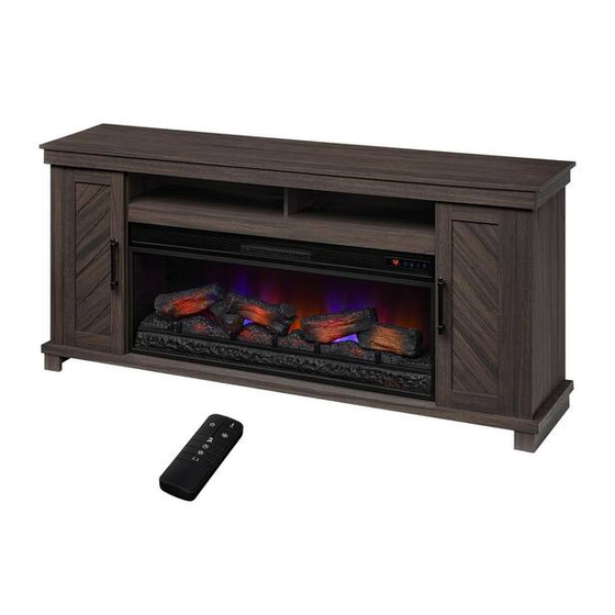
USE AND CARE GUIDE
CHALLIS ELECTRIC FIREPLACE MEDIA MANTEL
Questions, problems, missing parts?
Before returning to the store, call StyleWell Customer Service
8 a.m. - 7 p.m., EST, Monday - Friday, 9 a.m. - 6 p.m., EST, Saturday
1-877-527-0313
HOMEDEPOT.COM
THANK YOU
We appreciate the trust and confidence you have placed in StyleWell through the purchase of this electric fireplace. We strive to continually
create quality products designed to enhance your home. Visit us online to see our full line of products available for your home improvement
needs. Thank you for choosing StyleWell!
Advertisement
Table of Contents

Subscribe to Our Youtube Channel
Related Manuals for StyleWell 1007529322


Summary of Contents for StyleWell 1007529322
- Page 1 THANK YOU We appreciate the trust and confidence you have placed in StyleWell through the purchase of this electric fireplace. We strive to continually create quality products designed to enhance your home. Visit us online to see our full line of products available for your home improvement...
-
Page 2: Table Of Contents
Table of Contents Maximum Load Warning ........... 2 Package Contents .............. 7 Safety Information ............. 3 Assembly ..............8 Warranty ..............5 Operation ..............17 Pre-Assembly ............. 6 FCC/IC Information ............20 Hardware Included ........... 6 Care and Cleaning ........... 20 Product Specifications ............ -
Page 3: Safety Information
Safety Information Please read and understand this entire manual before attempting to assemble, operate or install the product. If you have any questions regarding the product, please call customer service at 1-877-527-0313, 8 a.m.-7 p.m., EST, Monday-Friday, WARNING: Under no circumstances should this fireplace be 9 a.m. - Page 4 Safety Information (continued) NOTE: Use care in assembling your new fireplace. Take your time and use the hardware provided and a quality Phillips head screwdriver. Never overtighten bolts. Do not sit on any part of the mantel. It is recommended to work on a soft surface like a rug or to lay out a blanket to protect the furniture from getting scratched during the assembly process.
-
Page 5: Warranty
Warranty Warranty 1 Year Limited Warranty: The manufacturer warrants that your new electric fireplace is free from manufacturing and material defects for a period of one year from date of purchase, subject to the following conditions and limitations. Install and operate this appliance in accordance with the installation and operating instructions furnished with the product at all times. -
Page 6: Pre-Assembly
Pre-Assembly HARDWARE INCLUDED Part Description Part Number Quantity USB output 980# P42MMP1697-AA Screw- 3 x 12 mm PH-SCRBLK004 Screw- 4 x 25 mm PH-SCRBLK018 Screw- 4 x 50 mm PH-SCRBLK006 Screw- 3 x 12 mm PH-SCRBLK007 Screw- 3.5 x 19 mm P42MMP1697-FF Back Panel Bracket PH-BKTBLK017... -
Page 7: Package Contents
Pre-Assembly (continued) PACKAGE CONTENTS NOTE: All panels are labeled left and right as viewed from the front of unit. Part Description Quantity Base Media Shelf Center Front Rail Left side Partition Right side Partition Center Leg Top Panel Left Side Panel Right Side Panel Partition Panel Side Back Panels... -
Page 8: Assembly
Assembly Installing the USB port Slide the USB output (AA) through the opening in the Media Shelf (B). Gently secure the USB output (AA) in place using Screws (BB) and a Phillips screwdriver. Attaching the Center Front Rail Attach the Center Front Rail (C) to the Media Shelf (B), inserting the pre-installed screws on the Center Shelf (B) into the pre-drilled holes on the Center Front Rail (C). - Page 9 Assembly (continued) Attaching the Center Leg Locate the Center Leg (F) and the Base (A) and secure in place using Screws (CC). Attaching the Base to the Center Assembly Align the side partitions of the center assembly with the pre-drilled holes in Base (A), as shown. Insert Screws (DD) through the Media Shelf (A) and into the pre-drilled holes on the edges of the center assembly as shown.
- Page 10 Assembly (continued) Attaching the Media Bay Partition Locate the Partition Panel (J). Insert the pre-installed dowels on the Partition Panel (J) into the pre-drilled holes on the Media Shelf (B). Insert Screws (DD) through the bottom of the Media Shelf (B) and into the pre-drilled holes on the edges of the Parti- tion Panel (J), with a Phillips screwdriver as shown.
- Page 11 Assembly (continued) Attaching the Top Panel Locate the mantel Top Panel (G) and align the pre-drilled screw holes on the Top Panel (G) with the pre-installed screws on the top edges of the main assembly. After inserting the screws into the holes, tighten the fasteners from underneath the mantel Top Panel (G) using a Phillips screwdriver as shown.
- Page 12 Assembly (continued) Preparing the Doors Locate the Left Door (N) and Right Door (O). Secure Euro Hinges (HH and II) to the Left Door (N) using Screws (JJ) on both the upper and lower hinge as indicated. Repeat steps on the Right Door (O). Place the Door Bumpers (KK) on the cabinet doors as indicated.
- Page 13 Assembly (continued) Accessing the Euro Hinge Remove the hinge light from the Euro Hinge (HH) to be able to access the hinge adjustment. Adjusting the Euro Hinge Using a Phillips screwdriver, loosen the screws to allow for adjustment of the hinge. The hinge can be adjusted in 3 dimensions.
- Page 14 Assembly (continued) Inserting the Adjustable Shelves Locate the two Adjustable Shelves (P). Insert the Shelf Pins (NN) into the pre-drilled holes on the inside of each cabinet side panel at your desired height. Align all pins to the same height to ensure your shelf is level.
- Page 15 Assembly (continued) Attaching the Support Panel Attach the Support Panel (Q) to the console using Bolts (PP) and a Phillips screwdriver as shown. Adjusting the Leveling Foot Adjust center support leg leveling foot by twisting until it is set at the desired height.
- Page 16 Assembly (continued) Installing the Tipping Restraint Hardware When the Tipping Restraint Hardware (QQ) is properly installed, it can provide protection against unexpected tipping of the unit due to small tremors, bumps or climbing. Each Tipping Restraint Hardware (QQ) includes one Unit Anchor, one Wall Anchor, one Anchor Tether, and four Anchor Screws.
-
Page 17: Operation
Operation Operation NOTE: The control panel can be accessed at the upper-right corner of the insert. Powering the Fireplace Adjusting the Flame There are 5 brightness levels that can be selected and OFF Push the Power button to supply power to all (00) setting. - Page 18 Operation (continued) Replacing the Hinge Light Battery Replacing the Remote Control Battery When the light stops operating or its range seems When the remote control stops operating or its range reduced, it is time to replace the battery with new seems reduced, it is time to replace the batteries with ones.
- Page 19 Operation (continued) Disposing of Used Batteries The battery may contain hazardous substances that could endanger the environment and human health. This symbol marked on the battery and/or packaging indicates that used battery should not be treated as municipal waste. Instead it shall be left at the appropriate collection point for recycling.
-
Page 20: Fcc/Ic Information
FCC/IC Information WARNING: Changes or modifications to this unit not expressly approved by the party responsible for compliance could void user’s authority to operate the equipment. NOTE: This equipment has been tested and found to comply with the limits for Class B digital device, pursuant to part 15 of the FCC Rules. -
Page 21: Troubleshooting
Troubleshooting PROBLEM ROOT CAUSE CORRECTIVE ACTION Fireplace has reached set temperature. Fireplace stopped heating before Set the fireplace to a higher temperature or Temperature around fireplace might be a few reaching the desired temperature. always “on”. degrees higher than other area in the room. Unplug the fireplace, remove the back panel of the fireplace and check that the The thermostat sensor is... - Page 22 Troubleshooting (continued) PROBLEM ROOT CAUSE CORRECTIVE ACTION Flame effect works but heater With the power on press and hold the Power function does not and the emberbed button on the control panel for 10 seconds. The heater is disabled. flashes when the Heater button is Once re-enabled the emberbed lights will pressed.
-
Page 23: Replacement Parts
Replacement Parts For replacement parts, call our customer service department at 1-877-527-0313, 8 a.m.-7 p.m., EST, Monday-Friday, 9 a.m. - 6 p.m., EST, Saturday. Part Description Qty. Part Number Flame Circuit Board Y21-S329-P40 Flame Generator Driver Mode P10-6-QSS Control Circuit Board Y21-S329-P184 Ember Bed with Log Set Y21-S329-P02... - Page 24 Questions, problems, missing parts? Before returning to the store, call StyleWell Customer Service 8 a.m. - 7 p.m., EST, Monday - Friday, 9 a.m. - 6 p.m., EST, Saturday 1-877-527-0313 HOMEDEPOT.COM Retain this manual for future use.
Need help?
Do you have a question about the 1007529322 and is the answer not in the manual?
Questions and answers