Sign In
Upload
Download
Table of Contents
Contents
Add to my manuals
Delete from my manuals
Share
URL of this page:
HTML Link:
Bookmark this page
Add
Manual will be automatically added to "My Manuals"
Print this page
×
Bookmark added
×
Added to my manuals
Manuals
Brands
hager Manuals
Circuit breakers
HW+ Series
Installation manual
hager HW+ Series Installation Manual
Air circuit breaker
Hide thumbs
1
Table Of Contents
2
3
4
5
6
7
8
9
10
11
12
13
14
15
16
17
18
19
20
21
22
23
24
25
26
27
28
29
30
31
32
33
34
35
36
37
38
39
40
41
42
43
44
45
46
47
48
49
50
51
52
53
54
55
56
57
58
59
60
61
62
63
64
65
66
67
68
69
70
71
72
73
74
75
76
77
78
79
80
81
82
83
84
85
86
87
88
89
90
91
92
93
94
95
96
97
98
99
100
101
102
103
104
105
106
107
108
109
110
111
112
113
114
115
116
117
118
119
120
121
122
123
124
page
of
124
Go
/
124
Contents
Table of Contents
Bookmarks
Table of Contents
Table of Contents
About this Manual
Using this Manual
Fixed Circuit Breakers
Description
Drawout Circuit Breakers
Description of the Electronic Trip Units
Circuit Breaker Usage Conditions
Circuit Breaker Operation
Description
Positions of the Drawout Circuit Breaker in the Chassis
Extracting the Drawout Circuit Breaker
Inserting the Drawout Circuit Breaker
Storage
Identification of the Circuit Breakers
Unboxing
Handling the Circuit Breakers
Advertisement
Quick Links
Download this manual
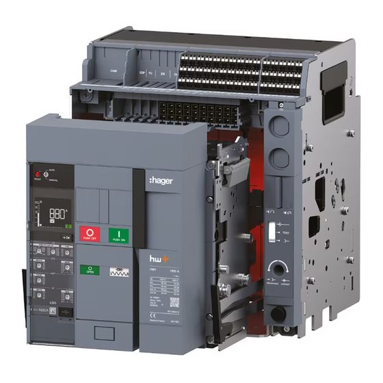
Installation manual
hw+
Air circuit breakers
HW1
RESET
AUTO
MANUAL
Ø5.8
MEASURES
In 1 6 0
=
0 A
Table of
Contents
Previous
Page
Next
Page
1
2
3
4
5
Advertisement
Table of Contents
Need help?
Do you have a question about the HW+ Series and is the answer not in the manual?
Ask a question
Questions and answers
Related Manuals for hager HW+ Series
Circuit breakers hager hw+ User Manual
Air circuit breaker up to 1600 a (120 pages)
Circuit breakers hager hw+ User Manual
Sentinel electronic trip units (72 pages)
Circuit breakers hager hw+ User Manual
Air circuit breakers up to 1600a (52 pages)
Circuit breakers hager hw+ User Manual
Sentinel energy electronic trip units (184 pages)
Circuit breakers hager HW1 Installation Manual
Air circuit breaker (124 pages)
Circuit breakers hager hw+ HW2 Installation Manual
Air circuit breaker (136 pages)
Circuit breakers hager h3+ Communication Instruction Manual
Moulded case circuit breakers (127 pages)
Circuit breakers hager h3+ HTP610H User Manual
Configuration tool (74 pages)
Circuit breakers hager h3+ PW1600 Installation Manual
Moulded case circuit breakers (64 pages)
Circuit breakers hager H400 Manual
Moulded case circuit breakers (4 pages)
Circuit breakers hager h3 x160 User Instructions
Moulded case circuit breakers 16 - 160 a (4 pages)
Circuit breakers hager h Series Manual
Auxiliaries hxc, d, e, f (4 pages)
Circuit breakers hager EP 501 Series User Instructions
Auxiliary for control by maintened contact (2 pages)
Circuit breakers hager TR521 Quick Start Manual
2 inputs / 1 flush mounted output for blinds or shutters mains powered (4 pages)
Circuit breakers hager TR 304A User Instruction
4 universal flush mounted inputs with battery (4 pages)
Circuit breakers hager TS 303 User Instruction
2 push-button input device with periodic emission (3 pages)
This manual is also suitable for:
Hw1
Table of Contents
Print
Rename the bookmark
Delete bookmark?
Delete from my manuals?
Login
Sign In
OR
Sign in with Facebook
Sign in with Google
Upload manual
Upload from disk
Upload from URL


Need help?
Do you have a question about the HW+ Series and is the answer not in the manual?
Questions and answers