hager hw+ User Manual
Air circuit breakers up to 1600a
Hide thumbs
Also See for hw+:
- User manual (120 pages) ,
- User manual (72 pages) ,
- User manual (184 pages)

Related Manuals for hager hw+


Summary of Contents for hager hw+
- Page 1 User manual Air circuit breakers up to 1600A RESET AUTO MANUAL Ø5.8 In 1 6 0...
-
Page 2: Table Of Contents
Contents Page 01 About this manual Safety instructions Using this manual 02 Circuit breaker operation Description Circuit breaker closing Circuit breaker opening Locking the opening and closing push buttons Locking the circuit breaker in the OFF position using padlocks Locking the circuit breaker in the OFF position using keylocks Locking the circuit breaker position in the chassis using padlocks Locking the circuit breaker position in the chassis using keylocks Racking interlock RI... -
Page 3: About This Manual
About this manual 1.1 Safety instructions Warnings and instructions This documentation contains safety advice which must be respected for your own safety and to prevent property damage. Safety advice relating to your own safety is identified by a safety warning symbol in the documentation. - Page 4 Appropriate use of Hager products Hager products are designed to be used only for the applications described in the catalogues and in the technical documentation relating to them. If products and components from other manufacturers are used, they must be recommended or approved by Hager.
-
Page 5: Using This Manual
User manual for Sentinel hw+ electronic trip 6LE007969A units You can download these publications and other technical information from our website: www. hager.com Contact Address Hager Electro SAS 132 Boulevard d’Europe 67215 Obernai France Phone + 33 (0)3 88 49 50 50 Website www.hager.com 6LE007331A... -
Page 6: Circuit Breaker Operation
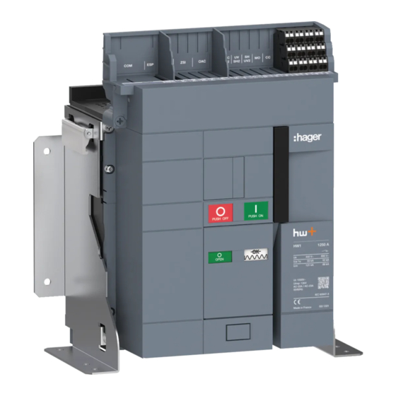
Circuit breaker operation 2.1 Description The hw+ circuit breaker has the following elements on the front: Charging handle Closing push button Closing spring status indicator Contact opening and closing indicator RESET AUTO Opening push button MANUAL RESET re-arm button In 1 6 0 Status indicators The combination of the two indicators shows the status of the circuit breaker. - Page 7 Circuit breaker operation 2.1 Description RESET re-arm button The RESET re-arm button is used to reset the circuit breaker after tripping (see Chapter 07 Circuit breaker closure after a trip operation). The operation of the RESET re-arm button depends on the Auto or Manual mode set using the adjustment dial on the right.
- Page 8 Circuit breaker operation 2.1 Description Closing spring The closing spring is used to mechanically close the circuit breaker. It must be charged first, and there are two procedures for this: - Manual charging Charge the spring using the charging handle until the status of the indicator changes. - Automatic charging If an MO charging motor is installed and powered, the closing spring charges automatically each time the circuit breaker closes.
-
Page 9: Circuit Breaker Closing
Circuit breaker operation 2.2 Circuit breaker closing DANGER Risk of electric shock, explosion or electric arc. Inspect the electrical installation and remove the tripping cause before closing the circuit breaker again. Never close a circuit breaker locally or remotely without first making sure that the installation complies with the safety standards. - Page 10 Circuit breaker operation 2.2 Circuit breaker closing Action Illustration Close the circuit breaker by pressing the closing push button Check that the indicators change status. If a charging motor is installed and powered, the closing spring charges automatically. 6LE007331A...
-
Page 11: Circuit Breaker Opening
Circuit breaker operation 2.3 Circuit breaker opening To open the circuit breaker: Action Illustration Check that the following indicators appear on the circuit breaker. Open the circuit breaker by pressing the opening push button Check that the indicators update: - indicator OPEN, - closing spring discharged indicator (case of manual charging),... -
Page 12: Locking The Opening And Closing Push Buttons
Circuit breaker operation 2.4 Locking the opening and closing push buttons The closing PUSH ON and opening PUSH OFF push buttons can be locked against any operation using the PBC push button covers. It prevents any unintended or unauthorised operation. The transparent PBC push button covers have an additional function. - Page 13 Circuit breaker operation 2.4 Locking the opening and closing push buttons Action Illustration Case 1 The opening push button is pressed continuously and the the closing push button is locked. Case 2 The opening push button and closing push button locked.
-
Page 14: Locking The Circuit Breaker In The Off Position Using Padlocks
Circuit breaker operation 2.5 Locking the circuit breaker in the OFF position using padlocks This locking device prevents the circuit breaker from closing using padlocks. Up to three Ø5–Ø8 mm padlocks can be installed. To activate or deactivate the locking device: Action Illustration Press the opening push... - Page 15 Circuit breaker operation 2.5 Locking the circuit breaker in the OFF position using padlocks Action Illustration ... Then close the padlock. Check that it is no longer possible to close the circuit breaker by pressing the closing push button To unlock the device, remove the padlock.
- Page 16 Circuit breaker operation 2.5 Locking the circuit breaker in the OFF position using padlocks Action Illustration Check that it is now possible to close the circuit breaker by pressing the closing push button ATTENTION Refer to manual 6LE007488A to install this locking accessory. 6LE007331A...
-
Page 17: Locking The Circuit Breaker In The Off Position Using Keylocks
Circuit breaker operation 2.6 Locking the circuit breaker in the OFF position using keylocks This locking device prevents the circuit breaker from closing using a key lock. Several types of locks can be installed. Ronis type lock Profalux type lock To activate or deactivate the locking device: Action Illustration... - Page 18 Circuit breaker operation 2.6 Locking the circuit breaker in the OFF position using keylocks Action Illustration Press the opening push button While holding down the opening push button , put the key back into the vertical position by turning it counter-clockwise. Remove the key.
- Page 19 Circuit breaker operation 2.6 Locking the circuit breaker in the OFF position using keylocks Action Illustration (continued) It remains pressed in. Check that it is no longer possible to close the circuit breaker by pressing the closing push button To unlock the device, insert the key into the lock.
- Page 20 Circuit breaker operation 2.6 Locking the circuit breaker in the OFF position using keylocks Action Illustration (continued) The push button returns to its initial position. Check that it is now possible to close the circuit breaker by pressing the closing push button ATTENTION The key cannot be removed in horizontal position.
-
Page 21: Locking The Circuit Breaker Position In The Chassis Using Padlocks
Circuit breaker operation 2.7 Locking the circuit breaker position in the chassis using padlocks This locking device locks the circuit breaker in the chassis and prevents the racking handle from being inserted. Up to three Ø5–Ø8 mm padlocks can be installed. To activate or deactivate the locking device: Action Illustration... - Page 22 Circuit breaker operation 2.7 Locking the circuit breaker position in the chassis using padlocks Action Illustration Position... then close the padlock. Check to ensure that it is not possible to insert the racking handle into the place to insert/withdraw. 6LE007331A...
- Page 23 Circuit breaker operation 2.7 Locking the circuit breaker position in the chassis using padlocks Action Illustration To unlock the device, remove the padlock. Check that the padlocking and position acknowledgement tab returns to its initial position. Check that it is now possible to insert the racking handle into the place to insert/withdraw.
-
Page 24: Locking The Circuit Breaker Position In The Chassis Using Keylocks
Circuit breaker operation 2.8 Locking the circuit breaker position in the chassis using keylocks This locking device locks the circuit breaker in the chassis and prevents the racking handle from being inserted. Several types of locks can be installed. Ronis type lock Profalux type lock (not included) Up to 2 locks can be installed in the housing. - Page 25 Circuit breaker operation 2.8 Locking the circuit breaker position in the chassis using keylocks To activate or deactivate the locking device: Action Illustration Check that the keylock is in the vertical position... or that the key is inserted in the vertical position. Check to ensure that it is not possible to insert the racking handle into the...
- Page 26 Circuit breaker operation 2.8 Locking the circuit breaker position in the chassis using keylocks Action Illustration To unlock the device, insert the key into the lock. Turn the key in the locking device in an anti-clockwise direction. Check that it is now possible to insert the racking handle into the place to insert/withdraw.
- Page 27 Circuit breaker operation 2.8 Locking the circuit breaker position in the chassis using keylocks Action Illustration The key cannot be removed in horizontal position. To remove it, turn until it is vertical. ATTENTION For the installation of this accessory, refer to the manual 6LE007677A. 6LE007331A...
-
Page 28: Racking Interlock Ri
Circuit breaker operation 2.9 RI open door racking lock This device prevents the racking handle being inserted into the circuit breaker rack in/rack out mechanism when the door of the electrical distibution board is open. To test the locking device: Action Illustration Open the electrical... - Page 29 Circuit breaker operation 2.9 RI open door racking lock Action Illustration Check to ensure that it is not possible to insert the racking handle into the place to insert/withdraw. Close the electrical distibution board door. Check that it is now possible to insert the racking handle into the place to insert/withdraw.
-
Page 30: Mechanical Interlock
Circuit breaker operation 2.10 Mechanical interlock The interlocking kit is used to interlock 2 to 3 circuit breakers installed vertically or horizontally in the electrical distibution board. In this way it prevents interlocked circuit breakers closing at the same time according to the types of application described below: Application Backup... -
Page 31: Positions Of The Drawout Circuit Breaker In The Chassis
Positions of the drawout circuit breaker in the chassis The position of the circuit breaker in the chassis is shown by the mechanical position indicator on the front. There are three different positions, connected, test and disconnected. Changing from one position to another is done using a racking handle. Before changing from one position to another, the padlocking and position acknowledgement tab must be pressed. -
Page 32: Positions Of The Drawout Circuit Breaker In The Chassis
Positions of the drawout circuit breaker in the chassis 4.1 Changing from connected position to test position WARNING Risk of electric shock Make sure that the device is only operated by qualified personnel in accordance with to the installation standards in force in the relevant country. To change from connected position to test position: Action Illustration... - Page 33 Positions of the drawout circuit breaker in the chassis 4.1 Changing from connected position to test position Action Illustration Insert the racking handle into the place to insert/ withdraw. Press the padlocking and position acknowledgement tab. 6LE007331A...
- Page 34 Positions of the drawout circuit breaker in the chassis 4.1 Changing from connected position to test position Action Illustration Turn the racking handle anti-clockwise..until the mechanical position indicator displays: TEST and the padlocking and position acknowledgement tab comes out of its housing.
-
Page 35: Changing From Test Position To Disconnected Position
Positions of the drawout circuit breaker in the chassis 4.2 Changing from test position to disconnected position ATTENTION Risk of property damage If the chassis is not fitted in an electrical panel, ensure it is correctly fastened before changing position. To change from test position to disconnected position: Action Illustration... - Page 36 Positions of the drawout circuit breaker in the chassis 4.2 Changing from test position to disconnected position Action Illustration ... until the mechanical position indicator displays: and the padlocking and position acknowledgement tab comes out of its housing. Clac ! Remove the racking handle.
-
Page 37: Changing From Disconnected Position To Test Position
Positions of the drawout circuit breaker in the chassis 4.3 Changing from disconnected position to test position WARNING Risk of electric shock Make sure that the device is only operated by qualified personnel in accordance with to the installation standards in force in the relevant country. To change from disconnected position to test position: Action Illustration... - Page 38 Positions of the drawout circuit breaker in the chassis 4.3 Changing from disconnected position to test position Action Illustration Press the padlocking and position acknowledgement tab. Turn the racking handle clockwise..until the mechanical position indicator displays: TEST and the padlocking and position acknowledgement tab comes out of its housing.
-
Page 39: Changing From Test Position To Connected Position
Positions of the drawout circuit breaker in the chassis 4.4 Changing from test position to connected position To change from test position to connected position: Action Illustration Check that the circuit breaker is in the test position and the TEST mechanical position indicator displays: Press the padlocking and... - Page 40 Positions of the drawout circuit breaker in the chassis 4.4 Changing from test position to the connected position Action Illustration ... until the mechanical position indicator displays: and the padlocking and position acknowledgement tab comes out of its housing. Clac ! Remove the racking handle.
-
Page 41: Extracting The Drawout Circuit Breaker
Extracting the drawout circuit breaker CAUTION Risk of the circuit breaker falling. Risk of injury by crushing. Before handling the circuit breaker, ensure the chassis is fastened within the electrical distribution board. Ensure the device is only handled by qualified personnel equipped with lifting equipment and suitable safety equipment. - Page 42 Extracting the drawout circuit breaker Action Illustration Remove the circuit breaker from the guide rails. 6LE007331A...
-
Page 43: Inserting The Drawout Circuit Breaker
Inserting the drawout circuit breaker CAUTION Risk of the circuit breaker falling. Risk of injury by crushing. Before handling the circuit breaker, ensure the chassis is fastened within the electrical distribution board. Ensure the device is only handled by qualified personnel equipped with lifting equipment and suitable safety equipment. - Page 44 Inserting the drawout circuit breaker Action Illustration Remove the lifting equipment. Push the circuit breaker to the back of the chassis without pushing on the guide rails. Push the guide rails to the back of the chassis. 6LE007331A...
-
Page 45: Closing The Circuit Breaker After Tripping
Closing the circuit breaker after tripping After tripping, the circuit breaker is open, the closing spring discharged or charged if a charging motor is installed. The electronic trip unit display flashes. To determine the tripping cause, refer to the 6LE007969A user manual for hw+ sentinel electronic trip units. - Page 46 Closing the circuit breaker after tripping Action Illustration If the circuit breaker rearming type is configured to MANUAL, move on to step 3. RESET AUTO MANUAL If the circuit breaker rearming type is set to AUTO, go directly to step RESET AUTO MANUAL...
- Page 47 Closing the circuit breaker after tripping Action Illustration Press the circuit breaker RESET re-arm button. Check that the closing spring is charged. The circuit breaker is now ready to be closed. 6LE007331A...
- Page 48 Closing the circuit breaker after tripping Action Illustration Then reset the electronic trip unit display. Make a short press on the button. The sentinel electronic trip unit display stops flashing: and becomes steady: 6LE007331A...
- Page 49 Closing the circuit breaker after tripping Action Illustration Press the button for more than 3 s . Check that the fault is cleared and that the display switches off. Close the circuit breaker by pressing the closing push button 6LE007331A...
- Page 50 Closing the circuit breaker after tripping Action Illustration Check that the indicators change status. Check that the ReadyToProtect indicator flashes on the electronic trip unit display. If the display remains off, connect an external battery to the USB-C socket to perform this check.
- Page 51 Notes 6LE007331A...
- Page 52 Hager Electro SAS 132 Boulevard d’Europe 67210 OBERNAI CEDEX www.hager.com 6LE007331A...
Need help?
Do you have a question about the hw+ and is the answer not in the manual?
Questions and answers