hager hw+ User Manual
Sentinel electronic trip units
Hide thumbs
Also See for hw+:
- User manual (120 pages) ,
- User manual (52 pages) ,
- User manual (184 pages)

Subscribe to Our Youtube Channel
Related Manuals for hager hw+


Summary of Contents for hager hw+
- Page 1 User manual sentinel electronic trip units RESET AUTO MANUAL Ø5.8 In 1 6 0...
-
Page 2: Table Of Contents
Description Display LI trip unit LSI trip unit LSIG trip unit Hager Power setup software 03 The types of protection device Overview of protections Long time delay protection against overcurrent Short time delay protection against overcurrent Instantaneous protection against overcurrent... -
Page 3: About This Manual
About this manual 1.1 Safety instructions Warnings and instructions This documentation contains safety advice which must be respected for your own safety and to prevent property damage. Safety advice relating to your own safety is identified by a safety warning symbol in the documentation. - Page 4 Appropriate use of Hager products Hager products are designed to be used only for the applications described in the catalogues and in the technical documentation relating to them. If products and components from other manufacturers are used, they must be recommended or approved by Hager.
-
Page 5: Using This Manual
6LE007897A You can download these publications and other technical information from our website: www. hager.com Contact Address Hager Electro SAS 132 Boulevard d’Europe 67215 Obernai France Phone + 33 (0)3 88 49 50 50 Website www.hager.com... -
Page 6: Sentinel Electronic Trip Unit
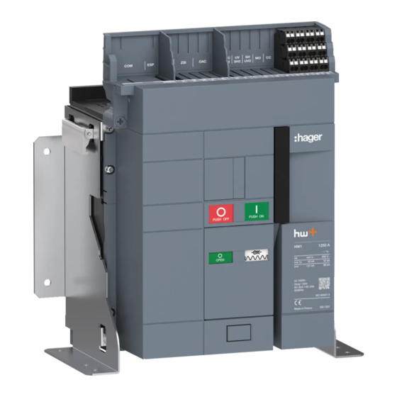
sentinel electronic trip unit 2.1 Description hw+ air circuit breakers are equipped with a sentinel electronic trip unit on the front to protect against overloads, short circuits and earth faults. It has a display and dials to configure the protection settings and monitor correct operation. 6LE007969A... - Page 7 ATTENTION To guarantee that the electronic trip unit functions well, it is recommended that a 24V DC SELV external power supply be connected (recommended product reference Hager HTG911H) to the TU terminal block. Without this external power supply, the electronic trip unit requires the presence of a minimum current of 120 A on one phase or 80 A per phase to provide its protection functions.
-
Page 8: Display
sentinel electronic trip unit 2.2 Display Description of the display sentinel electronic trip units are equipped with a display that makes it easy to adjust and read the causes of tripping of the hw+ circuit breakers. Overload indicator: displayed as soon as the current exceeds 105% of Ir. Error indicator: displayed when an error is detected. - Page 9 sentinel electronic trip unit 2.2 Display In standby, the ReadyToProtect indicator flashes, indicating normal operation of the sentinel electronic trip unit. A short press of the button displays a 1 screen showing the highest current of the 3 phases flowing through the circuit breaker. Current flowing through the circuit breaker in % of Ir.
-
Page 10: Li Trip Unit
sentinel electronic trip unit 2.3 LI trip unit The sentinel electronic trip unit is available in 3 versions: LI, LSI and LSIG LI sentinel trip unit The LI sentinel trip unit is used to protect long cable lines where the rated fault current is limited due to the impedance of the cable. -
Page 11: Lsi Trip Unit
sentinel electronic trip unit 2.4 LSI trip unit LSI sentinel trip unit The LSI sentinel trip unit is used to protect cables lines and equipment requiring a wide variety of protection settings. The dials are accessible from the front of the sentinel electronic trip unit, allowing precise adjustment of the protection parameter settings. -
Page 12: Lsig Trip Unit
sentinel electronic trip unit 2.5 LSIG trip unit LSIG sentinel trip unit The LSIG sentinel trip unit is used to protect cable lines and equipment for the case of a coupling system to TN earth or protection against earth faults is required. The dials are accessible from the front of the sentinel electronic trip unit, allowing precise adjustment of the protection parameter settings. -
Page 13: Hager Power Setup Software
2.6 Hager Power setup software The Hager Power setup software has been designed for testing and commissioning hw+ trip units. Thanks to the commissioning menu, it is possible to specifically generate a commissioning report proving that the protection settings comply with the short-circuit and selectivity calculations. - Page 14 • View the event logs and export them in a file in CSV format. • Display the status of the operating counters available (handling cycles, tripping operations...). The Hager Power setup software is available on the Hager website for your country. IT configuration required...
-
Page 15: The Types Of Protection Device
The types of protection device 3.1 List of protection devices The sentinel electronic trip unit protects against overcurrent and earth faults for all types of electrical distribution in accordance with the requirements of standards IEC 60947-1 and 60947-2. Protection system - Long delay against overcurrent - L: Overload protection - Short delay against overcurrent - S: Protection against low current short circuits - Instantaneous against overcurrent - I: Protection against high current short circuits... -
Page 16: Long Time Delay Protection Against Overcurrent
The types of protection device 3.2 Long time delay protection threshold against overcurrent The Long time delay protection is designed to protect the cables, the busbars and the busbar sheaths from current overloads. It includes a thermal memory function that temporarily stores the calculated thermal values so that the thermal effect of the cable heating remains available. - Page 17 The types of protection device 3.2 Long time delay protection against overcurrent tr adjustment range (s) 10.0 15.0 20.0 25.0 The trigger time tolerance for the long time delay protection is from 0 % to -20 %. Example: for tr = 5 s and I = 6 x Ir, the tripping time for the long time delay protection will be between 3.98 s and 5.03 s.
-
Page 18: Short Time Delay Protection Against Overcurrent
The types of protection device 3.3 Short time delay protection against overcurrent Short time delay protection is designed to protect against short circuits. Short time delay protection curve t (s) l²t I (A) Short time delay protection Short time delay parameters Isd (x Ir) Short time delay protection threshold against overcurrent tsd (s) - Page 19 The types of protection device 3.3 Short time delay protection against overcurrent An inverse time function I²t=K can be activated or deactivated when adjusting the short time delay. This I²t function makes it possible to improve selectivity with downstream devices. It is activated from the Isd pick-up and functions up to 10xIr.
-
Page 20: Instantaneous Protection Against Overcurrent
The types of protection device 3.4 Instantaneous protection against overcurrent Instantaneous protection is designed to protect against high short circuit currents. This protection is time-independent. Instantaneous protection curve t (s) I (A) Instantaneous protection Instantaneous protection parameters Ii (x In) Instantaneous protection threshold against overcurrent Adjusting the Ii pick-up setting The Ii pick-up is adjusted using the li dial. -
Page 21: Earth Fault Protection
The types of protection device 3.5 Earth fault protection The earth fault protection is used against phase-to-earth faults. The earth fault currents can reach a high enough amplitude that they are similar to a short circuit. It is based on the calculation of the sum of the phases and the neutral current. -
Page 22: Neutral Protection
The types of protection device 3.6. Neutral protection Neutral protection is factory-installed on 4P circuit breakers and as an option with the addition of the ENCT external neutral sensor on 3P versions. It is particularly useful if the neutral conductor section is less than that of the phases, or if the neutral conductor is heavily loaded (for example, in office buildings). -
Page 23: Zone Selective Interlocking Function (Zsi)
The types of protection device 3.7 Zone Selective Interlocking function (ZSI) The Zone Selective Interlocking (ZSI) function is designed to limit the electro-dynamic constraints on the installation (devices, conductors and busbars) in case of a short circuit fault or earth fault. It reduces the time taken to clear the electrical fault while maintaining the selectivity and coordination provided by the protection settings. - Page 24 Adjusting the ZSI protection setting To take into account zone selectivity, the ZSI protection must be activated on the hw+ circuit breakers using the Hager Power setup commissioning and test software. ZSI protection settings Short time delay protection ZSI...
- Page 25 The types of protection device 3.7 Zone Selective Interlocking function (ZSI) drawout circuit breaker RESET AUTO MANUAL In 1 6 0 Fixed circuit breaker RESET AUTO MANUAL In 1 6 0 6LE007969A...
-
Page 26: Protection Settings
Protection settings 4.1 Principle Follow the procedure below to adjust the protection devices. Action Illustration First, ensure that the circuit breaker is switched off and displays the following information: If this is not the case, open the circuit breaker by pressing the opening push button Open the transparent... - Page 27 Protection settings 4.1 Principle Action Illustration Adjust as required using the dials. The electronic trip unit must be powered in order to show the settings on the display. If necessary, remove the USB-C port cover to connect an external battery. Connect the external battery to the electronic trip unit’s USB-C port.
- Page 28 Protection settings 4.1 Principle Action Illustration Now, with each movement of the dial, show the corresponding setting..on the display to avoid converting the dial coefficients in your head into amps or seconds. Parameter adjusted Parameter unit: - in amps (A) for currents, - in seconds (S) for time delays.
- Page 29 Protection settings 4.1 Principle Action Illustration Check that if no action is performed for 30 seconds, the display returns to its standby screen. Once all the settings have been adjusted, disconnect the external battery. Close the USB-C port cover. Close the transparent cover.
- Page 30 Protection settings 4.1 Principle Action Illustration Apply a seal to the cover if necessary. 6LE007969A...
- Page 31 Protection settings 4.1 Principle Using a computer equipped with the Hager Power setup testing and commissioning software, it is possible to enter protection settings according to the values recorded in the Hagercad project. The computer must be connected to the USB-C port of the electronic trip unit.
-
Page 32: Long Time Delay (Ltd) Protection Setting
Protection settings 4.2 Long time delay (LTD) protection setting In our example, the circuit breaker rating is 1600 A. Example of lr current setting Ir = Ir1 x Ir2 x In = 0.5 x 0.92 x 1600 = 736 A t (sec) Characteristic of the affected curve WARNING... - Page 33 Protection settings 4.2 Long time delay (LTD) protection setting Example of setting of the tripping tr time delay tr = 2 s t (sec) Characteristic of the affected curve WARNING Risk of settings that are non-compliant with the short circuit and selectivity calculations.
-
Page 34: Short Time Delay (Std) Protection Setting
Protection settings 4.3 Short time delay (STD) protection setting In our example, the circuit breaker rating is 1600 A and Ir = 736 A. Example of Isd current setting Isd = 8 x Ir = 8 x 736 = 5888 A t (sec) Characteristic of the affected curve WARNING... - Page 35 Protection settings 4.3 Short time delay (STD) protection setting Example of tsd tripping time delay setting tsd = 0.05 s with I²t set to OFF t (sec) Characteristic of the affected curve WARNING Risk of settings that are non-compliant with the short circuit and selectivity calculations.
-
Page 36: Instantaneous (Inst) Protection Setting
Protection settings 4.4 Instantaneous (INST) protection setting In our example, the circuit breaker rating is 1600 A. Example of li current setting li = 15 x In = 15 x 1600 = 24000 A t (sec) Characteristic of the affected curve WARNING Risk of settings that are non-compliant with the short circuit and selectivity calculations. -
Page 37: Adjustment Of The Earth Fault (Gf) Protection Setting
Protection settings 4.5 earth fault (GF) protection setting In our example, the circuit breaker rating is 1600 A. Example of Ig current setting Ig = 0.4 x In = 0.4 x 1600 = 640 A t (sec) Characteristic of the affected curve WARNING Risk of settings that are non-compliant with the short circuit and selectivity calculations. - Page 38 Protection settings 4.5 earth fault (GF) protection setting Example of tg tripping time delay setting tg = 0.6 s with I²t set to OFF t (sec) Characteristic of the affected curve WARNING Risk of settings that are non-compliant with the short circuit and selectivity calculations.
-
Page 39: Adjustment Of The Neutral (N) Protection Setting
Protection settings 4.6 Neutral (N) protection setting Action Illustration Open the backup battery housing cover before connecting the USB-C socket (cf. Chapter 4.1 Principle). Adjust the desired setting See the diagram on the next page. then close the cover. ATTENTION The battery housing cover cannot be opened or closed if an external battery is connected to the USB-C port 6LE007969A... - Page 40 Protection settings 4.6 Neutral (N) protection setting In our example, the circuit breaker rating is 1600 A. Example of neutral protection N = 50% x Ir = 50% x 736 = 368 A t (sec) N=50% N=100% Characteristic of the affected curve WARNING Risk of settings that are non-compliant with the short circuit and selectivity calculations.
-
Page 41: Reviewing The Settings
Protection settings 4.7 Reviewing the settings To review the settings adjusted: Action Illustration Briefly press the button check that the following screen displays. It indicates the maximum instantaneous current as well as the phase concerned. Each short press switches between the following See the order of the screens on the next page. - Page 42 Protection settings 4.7 Reviewing the settings Maximum current flowing through the circuit breaker as Long Time Delay Long time well as the phase in question protection threshold delay → → ↗ ↘ Neutral protection Short Time Delay threshold protection threshold ↑...
- Page 43 Protection settings 4.7 Reviewing the settings Action Illustration To facilitate navigation, a screen identifier 1 indicates the position in relation to the number of screens available 2 . Screen identifier Trip unit Number of screens 5 - 6 in case of error 7 - 8 in case of error LSIG 9 - 10 in case of error...
-
Page 44: Commissioning The Circuit Breaker
-2. ATTENTION For any further information about commissioning the circuit breaker, contact Hager Technical Support. ATTENTION The Hager Power setup tool is recommended in order to carry out the protection settings when commissioning the electronic trip unit or before. 6LE007969A... -
Page 45: Alarm Management
Alarm management 6.1 PTA overload pre-alarm The sentinel electronic trip unit is used to manage 4 types of alarms: • Overload pre-alarm PTA • Overload alarm • Trip alarm • System alarm The PTA overload pre-alarm provides a warning when the situation is close to overload after a load current greater than 90% of Ir is reached. - Page 46 Alarm management 6.1 PTA overload pre-alarm The PTA overload pre-alarm is signalled by a screen of this type: Percentage of the Ir current reached Value in amps of the current flowing through the circuit breaker on the most highly loaded phase Relevant phase Overload pre-alarm indicator: Normal load zone...
-
Page 47: Overload Alarm
Alarm management 6.2 Overload alarm The overload alarm is activated as soon as the current ≥ 105% of the Ir value. In the event of an overload alarm, a screen of this type is displayed with the indicators 3 and 1 flashing. -
Page 48: Trip Alarm
Alarm management 6.3 Trip alarm If the circuit breaker trips (overload, short circuit, earth fault, trip unit fault), the circuit breaker opens. The electronic trip unit display is then powered by its backup battery. A screen of this type flashes for a maximum of 6 hours or until the fault is acknowledged. The use of a 24 V DC SELV external power supply can extend the display beyond 6 hours. -
Page 49: System Alarm
The Short time delay and Instantaneous and Instantaneous Protections protections cannot be deactivated deactivated simultaneously. Reactivate one of them. E100 to E200 Manufacturing fault Contact your Hager representative or local Hager technical support (contact details on the Hager website for your country). 6LE007969A... - Page 50 L1 current sensor out of service Contact your Hager representative or local Hager technical support (contact E002 L2 current sensor out of service details on the Hager website for your E003 L3 current sensor out of service country). E004 N current sensor out of service...
- Page 51 Alarm management 6.4 System alarm The critical system alarms are configurable via the unique HdWT parameter. To change this parameter: Action Illustration Press the key for longer than 10 s until this screen appears with an “ON” (if the current setting is at "ON").
-
Page 52: Maintenance Indicator
Maintenance indicator When the maintenance indicator is displayed, maintenance operations are required on the circuit breaker. Maintenance indicator ATTENTION If the maintenance indicator appears, contact your maintenance manager, Hager Technical Support or refer to the 6LE007897A maintenance guide. 6LE007969A... -
Page 53: Replacing The Backup Battery
Replacing the backup battery When the low or missing battery indicator appears, the electronic trip unit backup battery must be replaced. The backup battery can be replaced with the circuit breaker open or closed. Low or missing battery indicator ATTENTION If the backup battery is discharged, the electronic trip unit will be unable to display the cause of any tripping unless an external 24VDC SELV power supply is connected or an external battery is connected on the USB-C port of the electronic trip unit. - Page 54 Replacing the backup battery Action Illustration Insert a screwdriver into the notch. Then open the cover. Remove the USB-C port cover. 6LE007969A...
- Page 55 Replacing the backup battery Action Illustration Then connect an external battery to the USB-C port to continue powering the electronic trip unit's internal clock. Remove the old battery. 6LE007969A...
- Page 56 - Place the old battery only in a place intended for recycling. - To guarantee reliability, personal safety and material security, use only the Hager battery HWW463H, which is available as an accessory. ATTENTION...
- Page 57 Replacing the backup battery Action Illustration Check that there is no alarm on the display. Briefly press the button to acknowledge the battery low or absent indicator. Check that the battery low or absent indicator disappears after 5 seconds. ATTENTION If an error indicator appears, refer to Chapter 03 hw+ circuit breaker troubleshooting in the 6LE007897Ab maintenance guide.
- Page 58 Replacing the backup battery Action Illustration Close the USB-C port cover. Close the cover. Close the transparent cover. 6LE007969A...
- Page 59 Replacing the backup battery Action Illustration Apply a seal to the cover if necessary. 6LE007969A...
-
Page 60: Replacement Of The Rating Plug Of The Electronic Trip Unit
Replacement of the rating plug of the electronic trip unit The value of the nominal current In can be changed by replacing the rating plug located on the front face of the electronic trip unit. Reference Maximum rated Possible values Reference of circuit breaker current... - Page 61 Replacement of the rating plug of the electronic trip unit Action Illustration (continued) Open the circuit breaker by pressing the opening push button Check that the indicators change status. For the drawout circuit breaker, place the circuit breaker in the disconnected position (see Installation Manual 6LE007893A).
- Page 62 Replacement of the rating plug of the electronic trip unit Action Illustration If necessary, remove the seal from the transparent cover, which protects access to the trip unit, then unscrew the 4 screws. Lower the charging handle. Remove the cover in order to access the trip unit.
- Page 63 Replacement of the rating plug of the electronic trip unit Action Illustration Insert a flat screwdriver into the tab then apply leverage to unlock it. Remove the rating plug 6LE007969A...
- Page 64 Replacement of the rating plug of the electronic trip unit Action Illustration Position the tab of the new rating plug to the left. Insert the rating plug into its housing. Push the lever to the right to lock the rating plug. 6LE007969A...
- Page 65 Remove the external battery and replace the original rating plug or a new rating plug as described above. If the problem persists, contact your Hager representative or local Hager technical support (contact details for your country can be found on the Hager website).
- Page 66 Replacement of the rating plug of the electronic trip unit Action Illustration Remove the external battery. Close the USB-C port cover. Lower the charging handle. 6LE007969A...
- Page 67 Replacement of the rating plug of the electronic trip unit Action Illustration Place the cover back to its position. Fix the 4 screws. For the drawout circuit breaker, place it in the connected position. WARNING Risk of unexpected operation. Before closing the transparent cover, check the settings. 6LE007969A...
- Page 68 Replacement of the rating plug of the electronic trip unit Action Illustration Replace the transparent cover protecting access to the electronic trip unit if necessary. Charge the closing spring using the charging handle until the following indicators appear. Close the circuit breaker by pressing the closing push button 6LE007969A...
- Page 69 Replacement of the rating plug of the electronic trip unit Action Illustration check that the indicators change status. 6LE007969A...
- Page 70 Notes 6LE007969A...
- Page 71 Notes 6LE007969A...
- Page 72 Hager Electro SAS 132 Boulevard d’Europe 67210 OBERNAI CEDEX www.hager.com 6LE007969A...
Need help?
Do you have a question about the hw+ and is the answer not in the manual?
Questions and answers