Table of Contents
Advertisement
Quick Links
Advertisement
Chapters
Table of Contents

Related Manuals for hager h3+


Summary of Contents for hager h3+
- Page 1 Communication System manual Moulded Case Circuit Breakers up to 250 A...
- Page 2 6LE005550A...
- Page 3 Index Page 01 About this manual Safety advice Using this manual Abbreviations 02 Description of the h3+ communication system h3+ electronic trip units h3+ communication system HTP610H h3+ configuration tool HTD210H panel display Modbus communication module Energy AX/AL auxiliary 03 Function of the Energy trip unit Energy trip unit navigation and settings Protection function Measurement function...
- Page 4 6LE005550A...
- Page 5 About this manual Page Safety advice Using this manual Abbreviations 6LE005550A...
- Page 6 About this manual 1.1 Safety advice Warnings and instructions This documentation contains safety advice which must be respected for your own safety and to prevent property damage. Safety advice relating to your own safety is identified by a safety warning symbol in the documentation.
- Page 7 Appropriate use of Hager products Hager products are designed to be used only for the applications described in the catalogues and on the technical documentation relating to them. If products and components from other manufacturers are used, they must be recommended and approved by Hager.
- Page 8 Agardio Manager user manual 6LE001606B You can download these publications and other technical information from our website: www.hager.fr Contact Hager Electro SAS 132 Boulevard Address d‘Europe 67215 Obernai France Telephone + 33 (0)3 88 49 50 50 + 33 (0)3 88 49 50 50 www.hager.fr...
- Page 9 About this manual 1.3 Abbreviations Auxiliary Communication Port: Connector for the AX/AL Energy auxiliary ALarm: Fault-signal auxiliary contact AuXiliary: Open/closed auxiliary contact Communication Interface Port: Connector for the panel display and communication module Maintenance Interface Port: connector for HTP610H configuration tool Optional Alarm Contact: Connector for the optional alarm output contact Pre-Trip Alarm: Overload pre-alarm and connector for the...
-
Page 11: Table Of Contents
Description of the h3+ communication system Page h3+ electronic trip units 2.1.1 LSnI trip units 2.1.2 LSI trip units 2.1.3 LSIG trip units 2.1.4 Energy trip units 2.1.5 Meaning of LEDs and alarm notifications h3+ communication system HTP610H h3+ configuration tool 2.3.1 Field of application 2.3.2... -
Page 12: H3+ Electronic Trip Units
Description of the h3+ communication system 2.1 h3+ electronic trip units In addition to protecting against overloads and short-circuits, the h3+ moulded case circuit breakers equipped with electronic trip units provide great flexibility and fine-tuning capabilities for protection, improved selectivity values, and an extensive range of electrical measurements as well as communication functions. -
Page 13: Lsni Trip Units
Description of the h3+ communication system 2.1 h3+ electronic trip units 2.1.1 LSnI trip units LSnI t (s) I (A) - Configuration using adjustment dials. - Signalling the status of the trip unit via LED (Ready). - Signalling the overload alarm via LED (>Ir). - Possible adjustment of the threshold for the long time delay Ir and the short time delay current Isd. -
Page 14: Lsi Trip Units
Description of the h3+ communication system 2.1 h3+ electronic trip units 2.1.2 LSI trip units t (s) l²t In (A) - Configuration using adjustment dials. - Signalling the status of the trip unit via LED (Ready). - Signalling the PTA overload pre-alarm via LED (threshold 90% Ir). - Signalling the overload alarm via LED (>Ir). -
Page 15: Lsig Trip Units
Description of the h3+ communication system 2.1 h3+ electronic trip units Neutral adjustment (4P only) neutral protection (Ir, Isd) x … OFF - 50% - 100% instantaneous neutral protection Ii Same as phases time delay Same as tr, tsd and instantaneous 2.1.3 LSIG trip units t (s) -
Page 16: Energy Trip Units
Description of the h3+ communication system 2.1 h3+ electronic trip units I - Instantaneous protection Ii (accuracy +15/-15%) In = 40 A; 100 A: Ii (x In) 3 - 4 - 5 - 6 - 7 - 8 - 10 - 12 - 15 In = 160 A;... - Page 17 Description of the h3+ communication system 2.1 h3+ electronic trip units Trip alarms Customisable alarms System alarms See § 3.4 Managing alarms and logs Event logs Trips, Alarms Settings See § 3.4 Managing alarms and logs Integrated outputs PTA output contact OAC output contact Other configurations Refer to §...
-
Page 18: Meaning Of Leds And Alarm Notifications
Description of the h3+ communication system 2.1 h3+ electronic trip units 2.1.5 LED indicators on the front face and pop-ups on the embedded display indicate Meaning of LEDs and alarm changes in the operating status and alarm status of the LSnI, LSI, LSIG and Energy notifications circuit breakers. -
Page 19: H3+ Communication System
Modbus RTU communication bus. It is particularly suited to the Hager agardio.manager data server. h3+ communication system It is recommended to use the HTG911H 24 VDC supply to render this system functional. -
Page 20: Htp610H H3+ Configuration Tool
Description of the h3+ communication system 2.3 HTP610H h3+ configuration tool 2.3.1 The h3+ configuration tool is particularly recommended for configuration, testing, Field of application commissioning and diagnostic operations on h3+ circuit breakers with electronic trip units (LSnI, LSI, LSIG, Energy). HTP610H configuration tool lt enables users to do the following: - View the status of the Energy circuit breaker and its identification parameters... -
Page 21: Accessing The H3+ Configuration Web Pages
Description of the h3+ communication system 2.3 HTP610H h3+ configuration tool 2.3.3 The HTP610H h3+ configuration tool is composed of a portable configuration unit, Accessing the h3+ an MIP adapter lead, a connection cable and a 110 - 230 VAC charger adapter. The configuration WEB pages assembly is supplied in a carry case. -
Page 22: Htd210H Panel Display
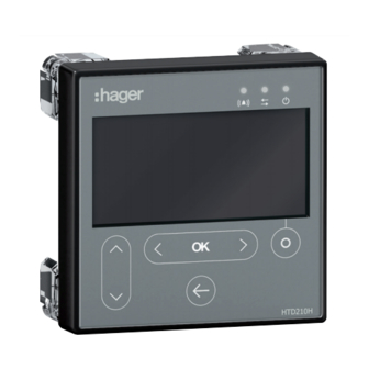
Description of the h3+ communication system 2.4 HTD210H panel display 2.4.1 The HTD210H panel display is an optional accessory which is used to configure the Presentation Energy trip unit and display the data on a panel or door near the circuit breaker. HTD210H panel display It is easily mounted on a door or a panel of a board thanks to its minimal depth behind the door. -
Page 23: Modbus Communication Module
Description of the h3+ communication system 2.5 Modbus communication module The communication module for the HTC3x0H series enables all the data saved by the h3+ Energy circuit breaker to be shared with a compatible Modbus RTU monitoring system. It is particularly recommended to be interfaced with the HTG411H agardio.manager data server. -
Page 24: Ax/Al Energy Auxiliary
Description of the h3+ communication system 2.6 AX/AL Energy auxiliary The AX/AL Energy auxiliary is devoted to the h3+ Energy circuit breaker. It enables the Energy trip unit to count the number of operation cycles, the number of trips related to an electromechanical fault and to specify the status (open/closed/tripped) of the circuit breaker contacts. - Page 25 Function of the Energy trip unit Page Energy trip unit navigation and settings 3.1.1 Protection menu 3.1.2 Measurements menu 3.1.3 Configuration menu 3.1.4 Information menu 3.1.5 Live mode 3.1.6 Navigation principles 3.1.7 Lock/unlock button Protection function 3.2.1 Long time delay protection 3.2.2 Short time delay protection 3.2.3...
-
Page 26: Energy Trip Unit Navigation And Settings
Function of the Energy trip unit 3.1 Energy trip unit navigation and settings The front face of the Energy electronic trip unit groups together the following elements: MIP connector h3+ joystick Embedded display Unlock button Ir max ajustment dial Indicator LEDs The embedded display enables the settings of the Energy trip unit to be accessed and the measurements and statuses to be viewed by means of the following 4 main menus: Protection... -
Page 27: Measurements Menu
Function of the Energy trip unit 3.1 Energy trip unit navigation and settings 3.1.2 Measurements menu Voltages on panel display The Measurements menu is composed of views enabling some of the measurements taken by the trip unit to be displayed: Display Variable measured Symbol... -
Page 28: Configuration Menu
Function of the Energy trip unit 3.1 Energy trip unit navigation and settings 3.1.3 Configuration menu The Configuration menu is composed of sub-menus used to display and modify the following trip unit parameters: - Time and date - Orientation of the display - Brightness - Standby mode. -
Page 29: Information Menu
Function of the Energy trip unit 3.1 Energy trip unit navigation and settings Standby mode is deactivated by one of the following events: - Action on the joystick - Alarm pop-up. Reset maximum measurement values sub-menu This sub-menu is used to reset the maximum stored current, voltage and power values. -
Page 30: Navigation Principles
Function of the Energy trip unit 3.1 Energy trip unit navigation and settings 3.1.6 The joystick on the left of the screen is used to navigate through the menus and Navigation principles confirm an action. Navigation between the main menus: Navigation within a sub-menu Central button Confirmation of an action 3.1.7... -
Page 31: Protection Function
Function of the Energy trip unit 3.2 Protection function The Energy electronic trip unit provides protection against overcurrents and insulation faults for all types of electrical power distribution. Its protection characteristics comply with the requirements of standard IEC 60947-2. List of protection functions - Long time delay protection - L: Protection against overloads - Short time delay protection - S: Protection against low current short circuits - Instantaneous protection - I: Protection against high current short circuits... -
Page 32: Long Time Delay Protection
Function of the Energy trip unit 3.2 Protection function 3.2.1 Long time delay protection is designed to protect against current overloads on Long time delay protection conductors and receivers in all electrical power distribution applications. The long time delay protection has an inverse time protection function including a thermal imaging function. - Page 33 Function of the Energy trip unit 3.2 Protection function tr adjustment range (s) The trip time tolerance for long time delay protection is -20% + 20ms to 0% + 30 ms. Example: For tr = 5 s and I = 6 x Ir, the trip time for long time delay protection will be between 3.98 s and 5.03 s.
-
Page 34: Short Time Delay Protection
Function of the Energy trip unit 3.2 Protection function 3.2.2 The short time delay protection is designed to protect against short circuits. Short time delay protection Short time delay curve t (s) l²t In (A) Short time delay protection Short time delay parameters Isd (x Ir) Short time delay protection threshold tsd (ms) - Page 35 Function of the Energy trip unit 3.2 Protection function This i²t function makes it possible to improve selectivity with downstream devices. It is activated from the Isd threshold and works up to 10 x Ir. t (s) l²t Short time delay protection I²t lr lsd 10xlr In (A)
-
Page 36: Instantaneous Protection
Function of the Energy trip unit 3.2 Protection function 3.2.3 The instantaneous protection is designed to protect against high strength short Instantaneous protection circuits.It is independent time protection. Instantaneous protection curve t (s) In (A) Instantaneous protection Instantaneous parameters Ii (x In) Instantaneous protection threshold Adjusting the Ii threshold The li trip threshold can be adjusted from the embedded display, the panel display... -
Page 37: Ground Protection
Function of the Energy trip unit 3.2 Protection function 3.2.4 Ground protection is protection against high strength insulation faults present in Ground protection installations with a TN-S earthing system. It is independent time protection. Ground protection curve t (s) l²tg In (A) Ground protection Ground parameters... -
Page 38: Neutral Protection
Function of the Energy trip unit 3.2 Protection function Ground protection is a protection against high strength insulation faults. It is similar to short time delay protection. It also has an inverse time I²t function, which can be activated or deactivated when adjusting this protection. This i²t function makes it possible to improve selectivity of ground faults with downstream devices. -
Page 39: Selectivity Per Zone Function (Zsi)
Function of the Energy trip unit 3.2 Protection function 3.2.6 The Zone Selective Interlocking function is designed to reduce electrodynamic Zone Selective Interlocking stress in the electrical power distribution system (conductors and busbars) when function (ZSI) time selectivity is activated. It applies to the upstream section of the electrical power distribution system composed mainly of open circuit breakers and moulded case type circuit breakers. - Page 40 Function of the Energy trip unit 3.2 Protection function Fault example b): - In the event of a fault downstream of circuit breaker Q2, only circuit breakers Q1 and Q2 detect the fault. Thanks to the connection cable between the circuit breakers, circuit breaker Q2 informs circuit breaker Q1 that it has detected the fault.
-
Page 41: Measurement Function
Function of the Energy trip unit 3.3 Measurement function 3.3.1 The Energy trip unit is used to measure the following types of variables: Overview of measurements Embedded Panel HTP610H Modbus display display tool Measurements in real-time Currents Phase and neutral I1, I2, I3;... -
Page 42: Measurements In Real-Time
Function of the Energy trip unit 3.3 Measurement function Embedded Panel HTP610H Modbus display display tool Averages over interval (Demand values) Active (kW), reactive (kvar), P Dmd, Q Dmd, S Dmd – apparent (kVA) power Total/per phase Max P Dmd, Max Q Dmd, Maximum power since last reset. - Page 43 Function of the Energy trip unit 3.3 Measurement function Version Version Electrical variable Symbol used Ground RMS (three-phase system – without neutral) RMS voltage V1N, V2N, V3N – RMS voltage U12, U23, U31 Phase rotation 1,2,3; 1,3,2 Frequency In addition, the Energy trip unit calculates the following associated electrical variables in real-time (every second): Version Version...
-
Page 44: Min/Max Measurements
Function of the Energy trip unit 3.3 Measurement function 3.3.3 The Energy trip unit calculates the real-time maximum and minimum values reached Min/max measurements since the last reset. Certain values are time stamped. All of these values take into account the positive and negative values. For example, if the previous maximum value was 25 and a value of -30 is measured, the new maximum value becomes -30. - Page 45 Function of the Energy trip unit 3.3 Measurement function Version Version Variable monitored Time stamp Minimum since reset - for each Ph-N voltage – - for each Ph-Ph voltage - for each Ph-N voltage unbalance – – - for phase-to-neutral unbalance maximums - for each Ph-Ph voltage unbalance...
-
Page 46: Measuring Unbalances
Function of the Energy trip unit 3.3 Measurement function - HTD210H display: Reset all min/max values and energy counters. - HTP610H configuration tool: Reset all min/max values and energy counters. 3.3.4 The Energy trip unit calculates in real-time (every second) current and voltage Measuring unbalances unbalances. -
Page 47: Power Measurements
Function of the Energy trip unit 3.3 Measurement function List of unbalance values: Version Version Electrical variable Symbol used Phase current unbalance I1 Unb, I2 Unb, I3 Unb Neutral current unbalance IN Unb – Instantaneous maximum phase current Max Unb I –... - Page 48 Function of the Energy trip unit 3.3 Measurement function Details about the calculations The calculations of these powers take into account the harmonics up to rank 31. Symbol Definition Total number of samples per network period Period measured, in seconds k sample number of phase p current k sample number of voltage between phase p and neutral Phase difference between the current and the voltage for phase p...
-
Page 49: Energy Measurements
Function of the Energy trip unit 3.3 Measurement function 3.3.6 The Energy trip unit calculates the various energy levels by integrating the Energy measurements instantaneous power over a network period. The Energy trip unit supplies several energy counters which can count up to 4,294,967,295 kWh / kvarh / kVAh. - Page 50 Function of the Energy trip unit 3.3 Measurement function - Synchronised integration period (Sync. Bus) Fixed integration interval The calculation intervals are consecutive. A new average value is calculated at the end of the interval. T 15 min T 15 min T 15 min t (min) IEC 1284/07...
- Page 51 Function of the Energy trip unit 3.3 Measurement function Synchro Synchronised integration interval Averaged values maximum For each averaged value (Demand value) period calculated, the maximum value over the time interval is stored. The maximum values can be reset via the HTP610H configuration tool or via the HTD210H display.
-
Page 52: Measuring Total Harmonic Distortion (Thd)
Function of the Energy trip unit 3.3 Measurement function Version Version Panel HTP610H Electrical variable Symbol Modbus display tool Max Q1 Dmd, Maximum reactive power Max Q2 Dmd, – per phase Max Q3 Dmd Maximum total reactive Max Qtot Dmd power Max S1 Dmd, Maximum apparent... -
Page 53: Measuring Power Factors
Function of the Energy trip unit 3.3 Measurement function Total harmonic distortion of voltage THD, THDU, THDV The THD of voltage is the percentage of the root-mean-square value of harmonic voltages of a rank above one, compared to the root-mean-square value of the harmonic voltage of rank one. - Page 54 Function of the Energy trip unit 3.3 Measurement function The power factors and the cos are energy distribution quality indicators. Improving these indicators facilitates the following: - Decrease the reactive energy consumption which may reduce penalties related to electrical consumption costs - Reduce the cross-section of the cables - Reduce line losses - Reduce the voltage drop...
-
Page 55: Configuring Measurements
Function of the Energy trip unit 3.3 Measurement function IEEE convention P < 0 P > 0 Capacitive Inductive Q > 0 (lead or ahead) (lag or delay) PF > 0 PF < 0 > 0 < 0 Inductive Capacitive Q <... - Page 56 Function of the Energy trip unit 3.3 Measurement function Setting the power sign convention The power sign convention parameter is used to configure the power sign according to the supply direction of the Energy circuit breaker. Positive Positif Negative Négatif Power sign P sign convention Default setting...
- Page 57 Function of the Energy trip unit 3.3 Measurement function Symbol Definition Active power L1 Active power L2 Active power L3 Reactive power L1 Reactive power L2 Reactive power L3 Apparent power L1 Apparent power L2 Apparent power L3 Total apparent power: Vector addition Total apparent power: Arithmetic addition On the figure above, the value of total apparent power SA by arithmetic addition is greater than the value of total apparent power SV by vector addition.
-
Page 58: Accuracy Of Measurements
Function of the Energy trip unit 3.3 Measurement function IEC convention P < 0 P > 0 Capacitive Inductive Q > 0 (lead or ahead) (lag or delay) PF > 0 PF < 0 > 0 Inductive Capacitive Q < 0 (lag or delay) (lead or ahead) PF >... - Page 59 Function of the Energy trip unit 3.3 Measurement function For a measurement taken at another temperature, within the temperature range of - 25 °C...+ 70 °C, the temperature accuracy derating coefficient is 0.05% per °C. The accuracy range is the part of the measuring range for which the defined accuracy is obtained;...
-
Page 60: Managing Alarms And Logs
Function of the Energy trip unit 3.4 Managing alarms and logs 3.4.1 The Energy trip unit is used to manage four types of alarms: Principle of Energy - PTA overload pre-alarm trip unit alarms - Trip alarm - Customisable alarm - System alarm The PTA overload pre-alarm provides a warning about the imminent trip risk due to a current overload. -
Page 61: Pta Overload Pre-Alarm
Function of the Energy trip unit 3.4 Managing alarms and logs 3.4.2 PTA overload pre-alarm Normal load Pre-warning monitoring Pre-trip warning 6LE005550A... -
Page 62: Trip Alarms
Function of the Energy trip unit 3.4 Managing alarms and logs 3.4.3 The trip alarms indicate a trip event and provide information about its cause. Trip alarms The possible causes of tripping are: - Trip related to long time delay protection - Trip related to short time delay protection - Trip related to instantaneous protection - Trip related to ground fault protection... -
Page 63: Customisable Alarms
Function of the Energy trip unit 3.4 Managing alarms and logs 3.4.4 Customisable alarms make it possible to monitor any measuring event detected by Customisable alarms the Energy trip unit. It is possible to define up to 12 alarms for a single trip unit. Each alarm is dedicated to monitoring a single measurement. - Page 64 Function of the Energy trip unit 3.4 Managing alarms and logs Activation by negative breach In the case of a negative breach of a threshold, activation of the alarm is dependent on the activation threshold being negatively breached. Lower breach Symbol Meaning Activation threshold...
- Page 65 Function of the Energy trip unit 3.4 Managing alarms and logs Symbol Meaning Activation value Activation time delay Deactivation time delay Managing time delays The time delays of customisable alarms are managed by 2 counters which are normally at 0 For the activation time delay, the counter: - Is increased when the activation condition is met - Is decreased if the activation condition is not met and if the...
-
Page 66: System Alarms
Function of the Energy trip unit 3.4 Managing alarms and logs Symbol Meaning Activation threshold Deactivation threshold Activation time delay Deactivation time delay There are three system alarms: 3.4.5 - Internal trip unit error System alarms - Trip unit temperature alarm - Rupture of the neutral pole They correspond to predefined events: Internal trip unit error... -
Page 67: Configuring Alarms
Function of the Energy trip unit 3.4 Managing alarms and logs Note These system alarms can be assigned to the OAC output contact. In this case, the OAC pop-up will be added to other pop-ups on the respective displays. 3.4.6 Configuring the PTA overload pre-alarm Configuring alarms The trip threshold and time delay for the PTA overload pre-alarm can be adjusted. - Page 68 Function of the Energy trip unit 3.4 Managing alarms and logs Note To allocate the OAC contact to the PTA overload pre-alarm, the contact is forced to automatic mode and the contact opens when the alarm disappears. Configuring trip alarms Trip alarms can be configured from the HTD210H panel display, the HTP610H configuration tool and by using the Modbus connection via a HTC3x0H communication module.
- Page 69 Function of the Energy trip unit 3.4 Managing alarms and logs Possible Activation/ Version Version Measurement monitored activation deactivation conditions threshold ranges Power > 1 kW to 1000 kW Active power consumed per phase – < (increments of 0.1 kW) >...
-
Page 70: Alarm Log
Function of the Energy trip unit 3.4 Managing alarms and logs Possible Activation/ Version Version Measurement monitored activation deactivation conditions threshold ranges Average currents over interval (Demand currents) I1_dmd, I2_dmd, I3_dmd, > 0.2xIn to 10xIn Iavg_dmd < (increments of 0.1 A) >... - Page 71 Function of the Energy trip unit 3.4 Managing alarms and logs Custom alarm log Each custom alarm event is saved with the following information: - Description - User time - Machine time - Alarm appearance/disappearance Log of protection settings Every modification to one of the protection settings is saved in the log: - Ir - tr - Short time delay activation...
- Page 72 Function of the Energy trip unit 3.4 Managing alarms and logs By default, the date is set at 1st January 2000, and is reset when the trip unit is no longer supplied (no self-supply or external supply). Note It is recommended to use an external supply so that the user time is consistent, or to ensure that when using a communication bus, the monitoring system performs another synchronisation at each start-up.
- Page 73 Starting, commissioning, operation Page Plug connections and accessories 4.1.1 Plug connections 4.1.2 Connection accessories Starting and configuring the circuit breaker 4.2.1 Precautions for use before starting 4.2.2 Starting the Energy trip unit for the first time 4.2.3 Setting the max Ir setpoint and Ir current of the Energy trip unit 4.2.4 Configuration via the unlock button 4.2.5...
-
Page 74: Plug Connections And Accessories
Starting, commissioning, operation 4.1 Connectors and accessories 4.1.1 The Energy circuit breaker is equipped with specific connectors for connecting Connectors communication devices and accessories. PTA connector: Used to connect the PTA output contact to send the overload pre-alarm over a local signalling circuit. OAC connector: The OAC port is an output contact used to send the optional alarm over a local signalling circuit. -
Page 75: Connection Accessories
Starting, commissioning, operation 4.1 Connectors and accessories Energy P250 trip unit connectors Location of the PTA connector PTA connector 4.1.2 Connection accessories are available as an option. These are pre-wired adapters Connection accessories which are available in various lengths as required. Connector Accessories reference length... -
Page 76: Starting And Configuring The Circuit Breaker
Starting, commissioning, operation 4.2 Starting and configuring the circuit breaker 4.2.1 DANGER Precautions for use before starting Risk of serious injury or danger of death. Ensure that the power supply inlet upstream of the circuit breaker is cut off and isolated before connecting the accessories and devices for the communication system. - Page 77 Starting, commissioning, operation 4.2 Starting and configuring the circuit breaker Here is the procedure to follow in order to connect the supply directly to the CIP connector: Action Note Switch the Energy circuit breaker to the OFF or tripped position. Open the front cover of the The front cover of the circuit breaker can only be opened in circuit breaker.
-
Page 78: Starting The Energy Trip Unit For The First Time
Starting, commissioning, operation 4.2 Starting and configuring the circuit breaker 4.2.2 At first start-up, before being able to access the various menus, the embedded Starting the Energy trip unit display will ask the user to set the orientation, brightness and Standby mode. for the first time These settings can be confirmed using the joystick on the left-hand side of the display. -
Page 79: Setting The Max Ir Setpoint And Ir Current Of The Energy Trip Unit
Starting, commissioning, operation 4.2 Starting and configuring the circuit breaker 4.2.3 After having set the display, the Ir max setpoint and Ir current should be set. Setting the max Ir setpoint Proceed as follows. and Ir current of the Energy trip unit Action Note/Illustration... - Page 80 Starting, commissioning, operation 4.2 Starting and configuring the circuit breaker Action Note/Illustration At this stage it is possible to modify the other protection settings. To do this, it is important to remain in Unlocked mode Note Check that the entire setting parameters icon to the left of the setting value remains displayed in the inverted colour Move the navigation joystick upwards or downwards...
- Page 81 Starting, commissioning, operation 4.2 Starting and configuring the circuit breaker Action Note/Illustration Repeat steps 5 to 9 to perform another protection setting Move the joystick to the left to exit Unlocked mode and return to the Main menu. Note This procedure is used to change the protection settings for the trip unit only. Other modifications to the settings such as resetting the maximum measurement values, returning to factory configurations or authorising data write permission, can be performed via the unlock button.
-
Page 82: Configuration Via The Unlock Button
Starting, commissioning, operation 4.2 Starting and configuring the circuit breaker 4.2.4 After setting the max Ir setpoint, it is necessary to: Configuration via the - Set the other protection parameters for the circuit breaker unlock button - Set the trip unit clock - Possibly lock the circuit breaker configuration Proceed as follows: Action... - Page 83 Starting, commissioning, operation 4.2 Starting and configuring the circuit breaker Action Note/Illustration Press the centre of the joystick to confirm the new setting At this stage it is possible to modify other settings of the current menu. To do this, it is important to remain in Unlocked mode Note...
- Page 84 Starting, commissioning, operation 4.2 Starting and configuring the circuit breaker Information about setting the data write permission In order to enable or prohibit external devices from modifying the internal trip unit parameters (protection, measurement, configuration, etc.), it is possible to set data write permission.
-
Page 85: Configuring Live Mode
Starting, commissioning, operation 4.2 Starting and configuring the circuit breaker 4.2.5 Live mode is deactivated by default. Configuring Live mode To manage favourites, proceed as follows: Action Note/Illustration Move the joystick to the right to select the Measurements menu. Then press the joystick to access the Measurements menu. -
Page 86: Connecting The Communication Module
Starting, commissioning, operation 4.3 Connecting the communication module 4.3.1 The communication module is connected to the Energy circuit breaker using the CIP Connecting the module to adapter. The CIP adapter cable is composed of an RJ9 connector to connect to the the circuit breaker communication module and a suitable connector to connect to the CIP connector. - Page 87 Starting, commissioning, operation 4.3 Connecting the communication module Action Note/Illustration The communication module can be fitted on a DIN rail or Secure the side support to directly on the side of the circuit breaker using the side the communication module. support.
-
Page 88: Connecting The Communication Module Supply
Starting, commissioning, operation 4.3 Connecting the communication module 4.3.2 The external 24 VDC supply is connected to the communication module at the top Connecting the of the module to the 24 V s (+ / –) terminal. communication module supply HTC320H connection terminals Cross-section of the 24 V s (+ / –) terminal: 0.5 to 1.5 mm². -
Page 89: Assembling And Connecting The Ax/Al Energy Auxiliary
Starting, commissioning, operation 4.4 Assembling and connecting the AX/AL Energy auxiliary DANGER Risk of electrical contact The standard HXA02xA auxiliaries are not recommended for use with the Energy circuit breaker. Installing these auxiliaries in an Energy circuit breaker can result in short-circuit electrical faults between its terminals and the CIP connectors of the circuit breaker. - Page 90 Starting, commissioning, operation 4.4 Assembling and connecting the AX/AL Energy auxiliary P160 AX/AL Energy connection Energy P160 trip unit connectors P250 AX/AL Energy connection 6LE005550A...
-
Page 91: Connecting The Pta And Oac Output Contacts
Starting, commissioning, operation 4.5 Connecting the PTA and OAC output contacts The PTA output contact is connected using the HTC130H adapter available as an 4.5.1 option and compatible with LSI, LSIG and Energy circuit breakers. Connecting the PTA contact PTA wiring Here is the procedure to follow to connect the PTA contact: Action Note/Illustration... -
Page 92: Connecting The Oac Contact
Starting, commissioning, operation 4.5 Connecting the PTA and OAC output contacts 4.5.2 The OAC output contact is connected using the HTC130H adapter available as an Connecting the option and compatible with LSI, LSIG and Energy circuit breakers. OAC contact OAC wiring Here is the procedure to follow to connect the OAC contact: Action Note/Illustration... -
Page 93: Start-Up And Configuration Via The Htd210H Display
Starting, commissioning, operation 4.6 Start-up and configuration via the HTD210H display 4.6.1 Overview of the HTD210H display HTD210H display Component Description Screen LCD type Signalling LED Alarm – communication - Ready RJ9 jack At the rear of the display Context-sensitive key Function dependent on the menu displayed Left and Right keys to navigate to the left and Left/OK/Right keys... - Page 94 Starting, commissioning, operation 4.6 Start-up and configuration via the HTD210H display Main menus of the HTD210H display HTD210H display menus There are 5 main menus and a pop-up menu. Menu Description Protection: This menu enables the user to view the protection parameters and to modify them if authorised to do so.
-
Page 95: Connecting The Htd210H Display
Starting, commissioning, operation 4.6 Start-up and configuration via the HTD210H display 4.6.2 ATTENTION Connecting the HTD210H display Risk of damaging the HTD210H display Use of an inappropriate RJ9 lead may damage the display. Only use CIP adapters available as an option. The HTD210H panel display is connected to the Energy circuit breaker using the CIP adapter. -
Page 96: Htd210H Display Supply
Starting, commissioning, operation 4.6 Start-up and configuration via the HTD210H display 4.6.3 The 24 VDC supply to the HTD210H display must come from an external supply. HTD210H display supply The external 24 VDC supply is connected in two ways: - From the communication module connection if installed. - From the HTC140H 24 V CIP adapter connection. -
Page 97: Starting The Htd210H Display For The First Time
Starting, commissioning, operation 4.6 Start-up and configuration via the HTD210H display 4.6.4 The first time it is used, the display will ask you to choose the navigation language. Starting the HTD210H English is the default language offered. display for the first time To change the language: Action Screen... - Page 98 Starting, commissioning, operation 4.6 Start-up and configuration via the HTD210H display Here is the procedure to follow to change the password: Action Screen Open the Main menu - The presence of a padlock means that the screen is locked. Open the menu for entering the password - The password must be 4 figures long.
- Page 99 Starting, commissioning, operation 4.6 Start-up and configuration via the HTD210H display Action Screen Open the Configuration menu Select the sub-menu "Change the password" Confirm the selection and enter the new password Increase/decrease the value Select the next numbers and position the values Confirm the entry Consult the HTD210H panel display user manual...
-
Page 100: Configuration Recommendations Via Htd210H
Starting, commissioning, operation 4.6 Start-up and configuration via the HTD210H display 4.6.5 Consult the user manual for the HTD210H panel display beforehand to read the Configuration advice and instructions for using the product. recommendations via HTD210H Energy circuit breaker protection setting Before using the HTD210H display to configure the Energy circuit breaker protection level, it is necessary to set the max Ir setpoint on the Energy circuit breaker. - Page 101 Starting, commissioning, operation 4.6 Start-up and configuration via the HTD210H display HTD210H panel display configuration menu Managing the alarms and output contact of the Energy circuit breaker The settings for the alarms, and PTA and OAC output contacts can be accessed in the Alarm menu.
-
Page 102: Text Block: Activation Of Htd210H Alarms
Starting, commissioning, operation 4.6 Start-up and configuration via the HTD210H display 4.6.6 Activation of HTD210H Alarm priorities alarms The display manages the alarm warnings according to their level of priority Priority Actions Alarm LED Alarm notification Alarm stored as Stored in the list flashing (**) an event... - Page 103 Starting, commissioning, operation 4.6 Start-up and configuration via the HTD210H display Description of an alarm notification Display Description Trip alarm Custom alarm Appears when the active alarm has been assigned to the OAC output contact. This indicates that the OAC contact has been activated.
-
Page 104: Commissioning Via The Htp610H Configuration Tool
Starting, commissioning, operation 4.7 Commissioning via the HTP610H configuration tool List of active alarms All the descriptions of active alarms with a medium or high priority level can be accessed in the list of active alarms via the context-sensitive key. The notification windows for active alarms with a high priority level can be viewed after they have been cleared using the context-sensitive key when the Alarm icon is displayed. -
Page 105: Preparing The Htp610H Tool
Starting, commissioning, operation 4.7 Commissioning via the HTP610H configuration tool 4.7.1 ATTENTION Preparing the HTP610H tool The following instructions and explanations are also described more comprehensively in the HTP610H configuration tool user manual. Consult the user manual for the HTP610H configuration tool beforehand to read the advice and instructions for using the tool. - Page 106 Starting, commissioning, operation 4.7 Commissioning via the HTP610H configuration tool After start-up, the configuration unit supplies the trip unit of the h3+ circuit breaker and therefore enables the embedded display of the Energy trip unit to be used. Connecting to the configuration server via Wi-Fi Configuration unit and Wi-Fi.
- Page 107 Starting, commissioning, operation 4.7 Commissioning via the HTP610H configuration tool Opening the circuit breaker management session The configuration software can be accessed by two different login sessions: Administration session Circuit breaker management session The Administration session facilitates the The Circuit breaker management session following: facilitates the following: - Access the menus for managing h3+ LSnI,...
-
Page 108: Configuration Recommendations Via Htp610H
Starting, commissioning, operation 4.7 Commissioning via the HTP610H configuration tool 4.7.2 Energy circuit breaker protection setting Configuration Before attempting to set the Energy circuit breaker protection level with the recommendations via configuration tool, it is necessary to set the max Ir setpoint on the Energy trip unit. HTP610H Refer to §... - Page 109 Starting, commissioning, operation 4.7 Commissioning via the HTP610H configuration tool Measurement settings in the HTP610H tool Managing the alarms and output contacts of the Energy circuit breaker The Energy circuit breaker measurement parameters can be modified. The settings for the alarms and PTA and OAC output contact measurement parameters can be accessed from the Trip alarm and output contact parameters sub-menus.
-
Page 110: Trip Curve Test Via Htp610H
Starting, commissioning, operation 4.7 Commissioning via the HTP610H configuration tool 4.7.3 DANGER Trip curve test via HTP610H Risk of serious injury or danger of death. Ensure that the power supply inlet upstream of the circuit breaker is cut off and isolated before performing a trip curve test. -
Page 111: Pta And Oac Contact Test Via Htp610H
Starting, commissioning, operation 4.7 Commissioning via the HTP610H configuration tool 4.7.4 The HTP610H configuration tool is used to test the PTA output contact on the LSI, PTA and OAC contact test LSIG and Energy circuit breakers. It is also used to test the OAC output contact on via HTP610H the Energy circuit breaker. -
Page 112: Operation
Starting, commissioning, operation 4.8 Operation 4.8.1 Information available on the embedded display Displaying information on Excluding the setting values and measured values, the embedded display provides the embedded and panel the following information from the Information menu: display - Information about the last trip event by the trip unit - AX: Number of operation cycles - AL: Number of trips related to an electromechanical fault Note... - Page 113 Starting, commissioning, operation 4.8 Operation Information available on the HTD210H panel display The measurements selected as favourites can be viewed constantly thanks to Live mode. Note The favourites on the panel display are selected and configured independently of the embedded display of the h3+ Energy circuit breaker. The HTD210H panel display indicates the following information relating to the LEDs: Alarm Flashing red if a medium or high priority level alarm is...
-
Page 114: Displaying Data On The Htp610H Configuration Tool
Starting, commissioning, operation 4.8 Operation Note The pop-ups need to be cleared to access the display menus when the alarms remain activated. The panel display enables the following information to be consulted during its operating phase: - Protection settings and other trip unit settings - Measured values - Alarm settings - Alarm logs... -
Page 115: Displaying Operating Data On Agardio.manager
Starting, commissioning, operation 4.8 Operation - Trip unit temperature - Protection settings and other trip unit settings - Instantaneous and measured values (max, min, avg…) - Test in progress - Values tested - Alarm settings - Alarm logs - Events log (changing protection settings) - Trip unit identification information - AX: Status of the contact and number of opening/closing cycles - AL: Status of the contact and number of electromechanical fault trips... - Page 116 6LE005550A...
- Page 117 Communication via Modbus Page Modbus functionalities of the Energy circuit breaker Write protection and managing Modbus passwords Connecting the communication module to the Modbus network Configuring the Modbus of the communication module Communication with agardio.manager 6LE005550A...
-
Page 118: Modbus Functionalities Of The Energy Circuit Breaker
Most of the Modbus functions and standard exception codes are managed by the Energy circuit breaker. Note For more information about the Modbus functions and exception codes, please contact us. Note The table of Modbus registers is available on the Hager website. 6LE005550A... -
Page 119: Write Protection And Managing Modbus Passwords
Communication via Modbus 5.2 Write protection and managing Modbus passwords WARNING Risk of nuisance tripping and faulty tripping. Only qualified personnel are to set the protection levels remotely. Failure to respect these instructions may cause death, serious injuries or equipment damage. Remote modifications made to the Modbus registers may be dangerous for personnel near the circuit breaker or may cause damage to the equipment if the protection parameters are modified. -
Page 120: Connecting The Communication Module To The Modbus Network
Communication via Modbus 5.3 Connecting the communication module to the Modbus network ATTENTION Risk of loss of Modbus data Use of connection cables other than those recommended may result in functional impairments of the Modbus connection and consequently loss of data. The communication module is connected to the Modbus wiring chain using specific cables available as an option. - Page 121 Communication via Modbus 5.3 Connecting the communication module to the Modbus network Cables Length Reference 0,2 m HTG480H HTG481H RJ45 – RJ45 cable HTG482H HTG484H HTG471H RJ45 – RJ45 cable with ground wire HTG472H HTG474H RJ45 cable – bare wire and HTG465H ground wire Modbus bare cable...
-
Page 122: Configuring The Modbus Of The Communication Module
Communication via Modbus 5.4 Configuring the Modbus communication module The parameters of the Modbus communication module can be adjusted on the front face using the adjustment dials and selector: - Modbus address - Parity - BAUD rate - 120Ω resistance Note The Modbus communication module has a 120 Ω... -
Page 123: Communication With Agardio.manager
Communication via Modbus 5.5 Communication with agardio.manager See the agardio.manager user manual HTG410H/HTG411H installation guide 6LE005550A... - Page 124 6LE005550A...
- Page 125 Support Page Troubleshooting 6LE005550A...
- Page 126 - On the Energy 3P trip unit, check that the neutral orange protection is deactivated. "Communication error" message on the - Contact your Hager technical support. – embedded display - Check whether the external 24 VDC supply is supplied and connected to one of the CIP connectors Contact of the circuit breaker.
- Page 127 6LE005550A...
Need help?
Do you have a question about the h3+ and is the answer not in the manual?
Questions and answers