Table of Contents
Advertisement
Quick Links
Advertisement
Table of Contents

Subscribe to Our Youtube Channel
Related Manuals for Vivitek DU70 Series


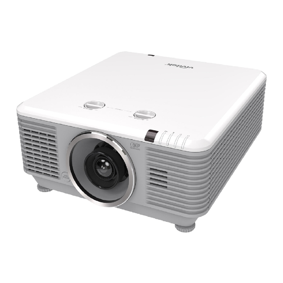
Summary of Contents for Vivitek DU70 Series
- Page 1 DU70x DU71x Series...
- Page 2 Copyright This publication, including all photographs, illustrations and software, is protected under international copyright laws, with all rights reserved. Neither this manual, nor any of the material contained herein, may be reproduced without written consent of the author. © Copyright 2018 Disclaimer The information in this document is subject to change without notice.
- Page 3 Important Safety Information Important: It is strongly recommended that you read this section carefully before using the projector. These safety and usage instructions will ensure that you enjoy many years of safe use of the projector. Keep this manual for future reference. Symbols Used Warning symbols are used on the unit and in this manual to alert you of hazardous situations.
- Page 4 LASER WARNING This symbol indicates that there is a potential hazard of eye exposure to laser radiation unless the instructions are closely followed. CLASS 3R LASER PRODUCT This Laser Product is designated as Class 3R during all procedures of operation. LASER LIGHT - AVOID DIRECT EYE EXPOSURE.
- Page 5 Product labels (DU70x Series) Below drawing show the label’s location Hazard Warning Symbol and Aperture Label Explanatory Label Explanatory Label — iv —...
- Page 6 Product labels (DU71x Series) Below drawing show the label’s location Hazard Warning Symbol and Aperture Label Explanatory Label – v –...
- Page 7 Location of laser aperture Below drawing is the laser aperture location. Be careful not to let the eye see the light directly. Laser aperture Interlock switches This machine has 2 (Top cover x 1, Lens x 1) Interlock switches to protect the laser light Leakage. 1.
- Page 8 Projector Installation Notice There is no limitation angle for projector installation. Allow at least 50 cm clearance around the exhaust vent. Minimum 500mm Minimum 500mm Minimum 500mm (19.69 inch) (19.69 inch) (19.69 inch) Minimum 500mm (19.69 inch) Minimum 100mm (3.94 inch) Minimum 500mm (19.69 inch)
- Page 9 Verify Installation Location To supply power, the 3-blade (with earthing lead) socket should be used to ensure proper grounding and equalized ground potential for all of the equipment in the Projector System. The power code provided with the Projector should be used. In case of any missing item, other qualified 3-blade (with earthing lead) power cord can be used as substitution;...
- Page 10 Power Safety Only use the supplied power cord. Do not place anything on the power cord. Place the power cord where it will not be in the way of foot traffic. Remove the batteries from the remote control when storing or not in use for a prolonged period. Cleaning the Projector ...
- Page 11 Main Features Compatible with all major video standards including NTSC, PAL, and SECAM. A high brightness rating allows for presentations in daylight or in lit rooms. Flexible setup allows for front, rear projections. Line-of-vision projections remain square, with advanced keystone correction for angled projections.
-
Page 12: Table Of Contents
Table of Contents GETTING STARTED ................................1 ................................1 ACKING HECKLIST ............................... 2 IEWS OF ROJECTOR ARTS Front-right View ................................2 Top view ..................................3 Side view—On-Screen Display (OSD) buttons and IO ................... 4 Bottom view ................................... 6 ..............................8 EMOTE ONTROL ARTS... - Page 13 ..........................62 OMMON ROBLEMS AND OLUTIONS ............................62 IPS FOR ROUBLESHOOTING LED E ..............................63 RROR ESSAGES ................................63 MAGE ROBLEMS ..............................64 IGHT OURCE ROBLEMS ............................64 EMOTE ONTROL ROBLEMS ................................64 UDIO ROBLEMS ..........................64 AVING THE ROJECTOR ERVICED HDMI Q &...
-
Page 14: Getting Started
ETTING TARTED Packing Checklist Carefully unpack the projector and check that the following items are included: Projector Remote Control VGA Cable (1.8m) Power Cord (1.8m) (Batteries Included) CD-ROM Warranty Card Quick Start Guide (This User's Manual) Contact your dealer immediately if any items are missing, appear damaged, or if the unit does not work. It is recommend that you keep the original packing material should you ever need to return the equipment for warranty service. -
Page 15: Views Of Projector Parts
Views of Projector Parts Front-right View 2 3 4 ABEL ESCRIPTION EE PAGE Vent Cool air intake. Tilt Adjuster Rotate adjuster lever to adjust angle position. Lens Release Button For release Lens. Anti-dust cap Anti-dust cap IR Receiver Receives IR signal from remote control. LEDs Displays the projector status. -
Page 16: Top View
Top view 1 2 3 4 5 ABEL ESCRIPTION EE PAGE Power LED Display the power on/off sequence status. Light source LED Display the light source status. Temp LED Display the thermal status. Filter LED Display the filter replacing warning message. IR Receiver Receives IR signal from remote control. -
Page 17: Side View-On-Screen Display (Osd) Buttons And Io
Side view—On-Screen Display (OSD) buttons and IO 1 2 3 4 5 6 7 8 9 12 13 ABEL ESCRIPTION EE PAGE MONITOR OUT Connect an RGB cable to a display. 3D-SYNC OUT (5V) Connect 3D IR glasses receiver unit. COMPUTER IN Connect an RGB cable from a computer or a video enabled device. - Page 18 ABEL ESCRIPTION EE PAGE AUTO Optimizes image size, position, and resolution. Navigates and changes settings in the OSD. Quick Menu – For Vertical Keystone. SOURCE Enter the Source menu. Navigates and changes settings in the OSD. Quick Menu – For Horizontal Keystone. When connected to the screen through a commercially available cable, the screen deploys automatically on start up of the projector.
-
Page 19: Bottom View
Bottom view 175mm 175mm [6.89"] [6.89"] ABEL ESCRIPTION EE PAGE Contact your dealer for information on mounting the projector on a Ceiling Mount Holes ceiling. Tilt Adjustor Rotate adjuster lever to adjust angle position. Note: When installing, ensure that you use only UL Listed ceiling mounts. For ceiling installations, use approved mounting hardware and M6 screws with a maximum screw depth of 12mm (0.47 inch). - Page 20 Reference drawings for stand Please hire an installation service provider (for a fee) for the design and manufacture of a customized stand to be used for portrait projection. Please ensure that the design complies with the following conditions: • Use the 6 screw holes at the back of the projector to secure it to the stand. Screw hole center dimension: 300 ×...
-
Page 21: Remote Control Parts
Remote Control Parts Important: 1. Avoid using the projector with bright fluorescent lighting turned on. Certain high-frequency fluorescent lights can disrupt remote control operation. 2. Be sure nothing obstructs the path between the remote control and the projector. If the path between the remote control and the projector is obstructed, you can bounce the signal off certain reflective surfaces such as projector screens. - Page 22 ABEL ESCRIPTION EE PAGE IR Transmitter Transmits signals to projector. Power On Turns the projector on. Displays the PC source selection. HDMI Displays the HDMI1/HDMI 2/DVI source selection (toggle). Navigates and changes settings in the OSD. Quick Menu – For Vertical Keystone. MENU Opens the OSD.
- Page 23 ABEL ESCRIPTION EE PAGE Displays the Volume setting bar. Volume/1 Number for Remote ID setting used. Displays the Contrast settings bar. Contrast/2 Number for Remote ID setting used. Mutes the built-in speaker. Mute/3 Number for Remote ID setting used. Displays the digital zoom settings bar. Zoom/4 Number for Remote ID setting used.
-
Page 24: Remote Control Operating Range
Remote Control Operating Range The remote control uses infrared transmission to control the projector. It is not necessary to point the remote directly at the projector. Provided you are not holding the remote perpendicular to the sides or the rear of the projector, the remote will function well within a radius of about 7 meters (23 feet) and 15 degrees above or below the projector level. -
Page 25: Setup And Operation
ETUP AND PERATION Inserting the Remote Control Batteries Remove the battery compartment cover by sliding the cover in the direction of the arrow. Insert the battery with the positive side facing up. Replace the cover. Caution: 1. Only use AAA batteries (Alkaline batteries are recommended). 2. -
Page 26: Installing Or Removing The Optional Lens
Installing or Removing the Optional Lens Caution: Do not shake or place excessive pressure on the projector or the lens components as the projector and lens components contain precision parts. Before removing or installing the lens, be sure to turn off the projector, wait until the cooling fans stop, and turn off the main power switch. -
Page 27: Removing The Existing Lens From The Projector
Removing the Existing Lens From the Projector Push the LENS RELEASE button to the unlock position. Grasp the lens. Rotate the lens counterclockwise. The existing lens will be disengaged. Pull out the existing lens slowly. — 14 —... -
Page 28: Starting And Shutting Down The Projector
Starting and Shutting down the Projector Securely connect the power cord and signal cable. When connected, the power led will flash green to solid green. Turn on the light source by pressing “ ” button on the projector or “ ”... - Page 29 If more than one input device is connected, press the SOURCE button and use ▲▼ to scroll among devices. (Component is supported through the RGB to Component adapter.) HDMI 1: High-Definition Multimedia Interface compatible HDMI 2 / MHL: High-Definition Multimedia Interface and Mobile High-Definition Link compatible ...
-
Page 30: Setting An Access Password (Security Lock)
Setting an Access Password (Security Lock) You can use the four (arrow) buttons to set a password and prevent unauthorized use of the projector. When enabled, the password must be entered after you power on the projector. (See Navigating the OSD on page Setting the OSD Language on page... - Page 31 You can use the cursor buttons ▲▼◄► either on keypad or IR remote control for password entry. You can use any combination including the same arrow five times, but not less than five. Press the cursor buttons in any order to set the password.
-
Page 32: Adjusting The Projector Level
Adjusting the Projector Level Take note of the following when setting up the projector: The projector table or stand should be level and sturdy. Position the projector so that it is perpendicular to the screen. Ensure the cables are in a safe location. You could trip over them. To raise the level of the projector, twist the adjusters counter clockwise. -
Page 33: Adjusting Projected Image Position Using Lens Shift
Adjusting Projected Image Position Using Lens Shift Vertical Horizontal Lens Shift Knob Lens Shift Knob The Lens Shift feature provides a lens shift function that can be used to adjust the position of the projected image either horizontally or vertically within the range detailed below. Shift is a unique system that provides lens shift while maintaining a much higher ANSI contrast ratio than traditional lens shift systems. -
Page 34: Adjusting The Horizontal Image Position
Adjusting the horizontal image position With the lens in the center position the horizontal image position can be adjusted to the left or right by up to a maximum of 5% of the image width. Note that the maximum horizontal image height adjustment can be limited by the vertical image position. -
Page 35: Adjusting The Zoom, Focus And Keystone
Adjusting the Zoom, Focus and Keystone Use the Image-zoom control (on the projector only) to resize the projected image and screen size. Use the Image-focus control (on the projector only) to sharpen the projected image. Press the buttons (on the projector or the remote control) to correct vertical or horizontal image-trapezoid or press the Keystone button (on the... -
Page 36: Adjusting The Volume
Adjusting the Volume Press the Volume buttons on the remote control. The volume control appears on the display. Press the ◄ / ► buttons on the keypad to adjust Volume +/-. Press the MUTE button to turn off the volume (This feature is available only on the remote). -
Page 37: On-Screen Display (Osd) Menu Settings
(OSD) M CREEN ISPLAY ETTINGS OSD Menu Controls The projector has an OSD that lets you make image adjustments and change various settings. Navigating the OSD You can use the remote control cursor buttons or the buttons on the projector to navigate and make changes to the OSD. -
Page 38: Setting The Osd Language
Setting the OSD Language Set the OSD language to your preference before continuing. 1. Press the MENU button. Press the cursor ◄► button to navigate to Settings 1. Press the cursor ▲▼ button to move to the Advanced 1 menu. (Enter) / ►... -
Page 39: Osd Menu Overview
OSD Menu Overview Use the following illustration to quickly find a setting or determine the range for a setting. Main Menu Sub Menu Settings Image Display Mode Presentation, Bright, Game, Movie, Vivid, TV, sRGB, DICOM SIM, User, User2 Brightness 0~100 Contrast 0~100 Computer... - Page 40 Main Menu Sub Menu Settings Settings 1 Source Source reference Input Source Select (IR/Keypad) Projection Normal, Real, Ceiling, Real+Ceiling Aspect Ratio Fill, 4:3, 16:9, Letter Box, Native, 2.35:1 Keystone H: -25 ~ +25 V: -30 ~ +30 Digital Zoom -10~10 Audio Volume 0~10...
- Page 41 Main Menu Sub Menu Settings Settings 2 Auto Source Off, On No Signal 0~180 Power Off Auto Power Off, On Light Mode Normal, Eco, Eco Plus, Dimming, Extreme Dimming, Custom Light Reset All Status Active Source Video Information Light Hours Software Version Remote ID Serial Number...
-
Page 42: Image Menu
Image Menu Attention ! All of display mode parameters when changed will be saved to user mode. Press the MENU button to open the OSD menu. Press the cursor ◄► button to move to the Image Menu. Press the cursor ▲▼ button to move up and down in the Image menu. Press ◄► to enter and change values for settings. -
Page 43: Computer Menu
Computer Menu Press the MENU button to open the OSD menu. Press ◄► to move to the Image menu. Press ▲▼ to move to the Computer menu and then press Enter or ►. Press ▲▼ to move up and down in the Computer menu. -
Page 44: Advanced Feature
Advanced Feature Press the Menu button to open the OSD menu. Press ◄► to move to the Image menu. Press ▼▲ to move to the Advanced menu and then press Enter or ►. Press ▼▲ to move up and down in the Advanced menu. -
Page 45: White Balance
White Balance Press the ENTER button to enter the White Balance sub menu. ESCRIPTION Press the ◄► buttons to adjust the Red Gain. R Gain Press the ◄► buttons to adjust the Green Gain. G Gain Press the ◄► buttons to adjust the Blue Gain. B Gain Press the ◄►... -
Page 46: Color Manager
Color Manager Press the Menu button to open the OSD menu. Press ◄► to move to the Image menu. Press ▼▲ to move to the Color Manager menu and then press Enter or ►. Press ▼▲ to move up and down in the Color Manager menu. -
Page 47: Settings 1 Menu
Settings 1 Menu Press the MENU button to open the OSD menu. Press the cursor ◄► button to move to the Settings 1 menu. Press the cursor ▲▼ button to move up and down in the Settings 1 menu. Press ◄► to enter and change values for settings. -
Page 48: Keystone
Keystone Press the Menu button to open the OSD menu. Press ◄► to move to the Settings 1 menu. Press ▼▲ to move to the Keystone menu and then press Enter or ►. Press ▼▲to adjust vertical values from -30 to 30. -
Page 49: Advanced 1 Feature
Advanced 1 Feature Press the Menu button to open the OSD menu. Press ◄► to move to the Settings 1 menu. Press ▲▼ to move to the Advanced 1 menu and then press Enter or ►. Press ▲▼ to move up and down in the Advanced 1 menu. - Page 50 3D Setting ESCRIPTION Press the cursor ◄► button to enter and select different 3D mode. Press the cursor ◄► button to enter and enable or disable 3D Sync Invert. 3D Sync Invert Press the cursor ◄► button to enter and select different 3D Format. 3D Format Press the cursor ◄►...
-
Page 51: Advanced 2 Feature
Advanced 2 Feature Press the Menu button to open the OSD menu. Press ◄► to move to the Settings 1 menu. Press ▲▼ to move to the Advanced 2 menu and then press Enter or ►. Press ▲▼ to move up and down in the Advanced 2 menu. -
Page 52: Corner
4 Corner (Enter) / ► to enter the 4 Corner sub menu. Press 1. Press the cursor ▲ / ▼ buttons to select a corner and press ENTER. 2. Press the cursor ▲ / ▼ buttons to adjust vertical and press the cursor ◄ / ► buttons to adjust horizontal. -
Page 53: Settings 2 Menu
Settings 2 Menu Press the MENU button to open the OSD menu. Press the cursor ◄► button to move to the Settings 2 menu. Press the cursor ▲▼ button to move up and down in the Settings 2 menu. ESCRIPTION Press the cursor ◄►... -
Page 54: Status
Status Press the cursor ▲▼ button to move up and down in the Settings 2 menu. Select the Status menu and press Enter or ► to enter. ESCRIPTION Active Source Display the activated source. Displays resolution/video information for RGB source and color standard for Video Video Information source. -
Page 55: Advanced 1 Feature
Advanced 1 Feature Press the Menu button to open the OSD menu. Press ◄► to move to the Settings 2 menu. Press ▲▼ to move to the Advanced 1 menu and then press Enter or ►. Press ▲▼ to move up and down in the Advanced 1 menu. - Page 56 Network ESCRIPTION Network State Displays the network connection status. Press ◄► to turn DHCP On or Off. Note: If you select DHCP Off, complete the IP Address, Subnet Mask, Gateway, and DHCP DNS fields. IP Address Enter a valid IP address if DHCP is turned off. Subnet Mask Enter a valid Subnet Mask if DHCP is turned off.
- Page 57 LAN_RJ45 Wired LAN Terminal functionalites Remote control and monitoring of a projector from a PC (or Laptop) via wired LAN is also possible. Compatibility with Crestron / AMX (Device Discovery) / Extron control boxes enables not only collective projector management on a network but also management from a control panel on a PC (or Laptop) browser screen.
- Page 58 LAN_RJ45 1. Connect an RJ45 cable to RJ45 ports on the projector and the PC (Laptop). 2. On the PC (Laptop), select Start → Control Panel →Network and Internet. – 45 –...
- Page 59 3. Right-click on Local Area Connection, and select Properties. 4. In the Properties window, select the Networking tab, and select Internet Protocol (TCP/IP). 5. Click Properties. 6. Click Use the following IP address and fill in the IP address and Subnet mask, then click OK. —...
- Page 60 7. Press the Menu button on the projector. 8. Select Settings2→ Advanced1 → Network 9. After getting into Network, input the following: DHCP: Off IP Address: 10.10.10.10 Subnet Mask: 255.255.255.0 Gateway: 0.0.0.0 DNS Server: 0.0.0.0 (Enter) / ►...
- Page 61 ATEGORY NPUT ENGTH IP Address Crestron Control IP ID Port Projector Name Projector Location Assigned To DHCP (Enabled) (N/A) IP Address Network Configuration Subnet Mask Default Gateway DNS Server Enabled (N/A) User Password New Password Confirm Enabled (N/A) Admin Password New Password Confirm For more information, please visit http://www.crestron.com.
- Page 62 Preparing Email Alerts 1. Make sure that user can access the homepage of LAN RJ45 function by web browser (for ex-ample, Microsoft Internet Explorer v6.01/v8.0). 2. From the Homepage of LAN/RJ45, click Alert Settings. 3. By default, these input boxes in Alert Settings are blank. –...
- Page 63 4. For Sending alert mail, input the following: The SMTP field is the mail server for sending out email (SMTP protocol). This is a required field. The To field is the recipient’s email address (for example, the projector administrator). This is a required field.
- Page 64 RS232 by Telnet Function Besides projector connected to RS232 interface with “Hyper-Terminal” communication by dedicated RS232 command control, there is alternative RS232 command control way, so called “RS232 by TELNET” for LAN/RJ45 interface. Quick Start-Guide for “RS232 by TELNET” Check and get the IP-Address on OSD of the projector. Make sure that laptop/PC can access the web-page of the projector.
- Page 65 Input the command format like the below: telnet ttt.xxx.yyy.zzz 23 (“Enter” key pressed) (ttt.xxx.yyy.zzz: IP-Address of the projector) If Telnet-Connection ready, and user can have RS232 command input, then “Enter” key pressed, the RS232 command will be workable. How to have TELNET enabled in Windows VISTA / 7 / 8 By default installation for Windows VISTA / 7 / 8, “TELNET”...
- Page 66 Select “Turn Windows features on or off” to open Have “Telnet Client” option checked, then press “OK” button. Specsheet for “RS232 by TELNET” : 1. Telnet: TCP 2. Telnet port: 23 (for more detail, kindly please get contact with the service agent or team) 3.
- Page 67 HDBaseT Setting ESCRIPTION Press the cursor ◄► button to enter and enable or disable HDBaseT Control. HDBaseT-IR/RS232 Press the cursor ◄► button to enter and enable or disable Front IR. Front IR Press the cursor ◄► button to enter and enable or disable Rear IR. Rear IR Note: 1.
-
Page 68: Advanced 2 Feature
Advanced 2 Feature Press the Menu button to open the OSD menu. Press ◄► to move to the Settings 2 menu. Press ▲▼ to move to the Advanced 2 menu and then press Enter or ►. Press ▲▼ to move up and down in the Advanced 2 menu. - Page 69 Source Filter Press the ENTER button to enter the Source Filter sub menu. ESCRIPTION Press the cursor ◄► button to enter and enable or disable the HDMI1 source. HDMI1 Press the cursor ◄► button to enter and enable or disable the HDMI2 / HDMI2/MHL MHL-compatible source.
-
Page 70: Maintenance And Security
AINTENANCE AND ECURITY Cleaning the Projector Cleaning the projector to remove dust and grime will help ensure trouble-free operation. Warning: 1. Be sure to turn off and unplug the projector at least 30 minutes before cleaning. Failure to do so could result in a severe burn. -
Page 71: Cleaning The Air Filter
Cleaning the Air Filter The air filter prevents dust from accumulating on the surface of the optical elements inside the projector. If the filter is dirty or clogged, your projector may overheat or degrading the projected image quality. Turn off the projector, and unplug the AC power cord from the AC outlet. -
Page 72: Replacing The Filter
Replacing the Filter Turn off the projector, and unplug the AC power cord from the AC outlet. Clean up the dust on the projector and around the air vents. Remove the screws from the filter module. Loosen Screws on the filter module. - Page 73 Lift the filter from the filter cover. Replace a new filter into cover. Replace the filter cover back to the projector. Turn on the projector and reset the Air Filter Timer after the Air Filter is replaced. Air Filter Timer Reset: Press MENU >...
-
Page 74: Using The Physical Lock
Using the Physical Lock Using the Kensington Security Slot If you are concerned about security, attach the projector to a permanent object with the Kensington slot and a security cable. Note: Contact your vendor for details on purchasing a suitable Kensington security cable. The security lock corresponds to Kensington’s MicroSaver Security System. -
Page 75: Troubleshooting
ROUBLESHOOTING Common Problems and Solutions These guidelines provide tips to deal with problems you may encounter while using the projector. If the problem remains unsolved, contact your dealer for assistance. Often after time spent troubleshooting, the problem is traced to something as simple as a loose connection. Check the following before proceeding to the problem-specific solutions. -
Page 76: Led Error Messages
LED Error Messages LED F RROR ESSAGES OWER IGHT ILTER Light Source Ready Start Flashing Cooling Flashing Over Temperature T1 1 blinks Over Temperature T2 2 blinks Over Temperature T3 3 blinks Over Temperature T4 4 blinks Over Temperature T5 5 blinks Thermal Break Sensor error 4 blinks... -
Page 77: Light Source Problems
Problem: The image is reversed Check the Projection setting on the Settings 1 menu of the OSD. Problem: The image is streaked Set the Frequency and Tracking settings on the Image->Computer menu of the OSD to the default settings. 2. To ensure the problem is not caused by a connected PC’s video card, connect to another computer. -
Page 78: Hdmi Q & A
HDMI Q & A Q. What is the difference between a “Standard” HDMI cable and a “High-Speed” HDMI cable? Recently, HDMI Licensing, LLC announced that cables would be tested as Standard or High- Speed cables. ˙Standard (or “category 1”) HDMI cables have been tested to perform at speeds of 75Mhz or up to 2.25Gbps, which is the equivalent of a 720p/1080i signal. -
Page 79: Specifications
PECIFICATIONS Specifications Model Name DU70x Series DU71x Series Display Type 0.67 WUXGA Type A Resolution WUXGA 1920x1200 Semi Short Short Throw STD Lens Throw Long Throw Super Long Throw Lens VL904G/LNS- VL906G/LNS- VL907G/LNS- VL908G/LNS-5LZ3 VL909G/LNS-5LZ2 5FX2 5SZ2 5STZ Throw Ratio 0.778 1.1~1.3 1.54~1.93... - Page 80 VGA x 1 Audio RCA (R/L) x 1 Output Terminals USB Type A for power support on WHDI x 1 3D-Sync out x 1 RS-232 in x 1 ( for serial in for control ) RS-232 out x 1 (serial out for Pass thru Daisy Chain) RJ45 x 1 (10/100Mbps) Control Terminals Screen Trigger : DC Jack x 1 (DC12V 200mA output function)
-
Page 81: Projection Distance Vs. Projection Size
Projection Distance vs. Projection Size Projection Distance Projection Distance and Size Table New Short throw projection lens: TR: 0.778; offset=55% Distance (m) 0.67 1.34 1.68 2.51 Diagonal (") 1723 2154 3231 Image Width (mm) Image Height (mm) 1077 1346 2019 h (mm) 1010 1111... - Page 82 Standard projection lens: TR: 1.54 ~ 1.93; offset=55% 1.66 3.33 4.16 8.31 1.66 3.32 6.63 9.95 Distance (m) Diagonal (") 300(*) Image Width (mm) 1723 2154 4308 1077 2154 4308 6462 Image Height (mm) 1077 1346 2692 1346 2692 4039 h (mm) 1346 1346...
-
Page 83: Timing Mode Table
Timing Mode Table Table of Supported Frequency The unit automatically determines PC signals to select the appropriate resolution. Some signals may require manual adjustment. DVI/HDMI/ RGB/BNC IGNAL ESOLUTION OMPOSITE OMPONENT ( KH NALOG IGITAL - ○ - - - NTSC 15.734 60.0 -... - Page 84 DVI/HDMI/ RGB/BNC IGNAL ESOLUTION OMPOSITE OMPONENT ( KH NALOG IGITAL - - ○ ○ 1280 x 960 60.0 60.0 - - ○ ○ 1280 x 960 85.9 85.0 - - ○ ○ 1360 x 768 47.7 60.0 - - ○ ○...
-
Page 85: Table Of Supported Frequency For 3D Mode
Table of Supported Frequency For 3D mode The unit automatically determines PC signals to select the appropriate resolution. Some signals may require manual adjustment. Input Signal for D-SUB/HDMI/DVI-D IGNAL ESOLUTION EFRESH SVGA 800 X 600 60/120 1024 X 768 60/120 HDTV(720P) 1280 X 720 60/120... -
Page 86: Projector Dimensions
Projector Dimensions 470mm [18.50"] – 73 –... -
Page 87: Regulatory Compliance
EGULATORY OMPLIANCE FCC Warning This equipment has been tested and found to comply with the limits for a Class B digital device pursuant to Part 15 of the FCC Rules. These limits are designed to provide reasonable protection against harmful interference when the equipment is operated in a commercial environment. -
Page 88: Communication Parameter Setup
PPENDIX Communication parameter setup You can use the serial control command to input commands for projector control or retrieve its operational data through Windows client terminal software, e.g. Hyper Terminal, with ASCII characters.You need to set up the following communication parameters in advance: Item Parameter:... - Page 89 OSD Function ASCII Settings/Return Values Auto Power Off Op auto.powoff 0-180 0 = Off Auto Power On Op auto.powon 1 = On 0 = Black 1 = Red Blank Screen Op no.signal 2 = Green 3 = Blue 4 = White Contrast Op contrast 0-100...
- Page 90 OSD Function ASCII Settings/Return Values HSG/Blue Gain Op Hsg.b.gain 0-100 HSG/Cyan Gain Op hsg.c.gain 0-100 HSG/Magenta Gain Op hsg.m.gain 0-100 HSG/Yellow Gain Op hsg.y.gain 0-100 HSG/Red/Saturation Op hsg.r.sat 0-100 HSG/Green/Saturation Op hsg.g.sat 0-100 HSG/Blue/Saturation Op Hsg.b.sat 0-100 HSG/Cyan/Saturation Op hsg.c.sat 0-100 HSG/Magenta/Saturation Op hsg.m.sat...
- Page 91 OSD Function ASCII Settings/Return Values HSG/White/Red Gain Op hsg.wr.gain 0-100 HSG/White/Green Gain Op hsg.wg.gain 0-100 HSG/White/Blue Gain Op Hsg.wb.gain 0-100 0 = Fill 1 = 4:3 2 = 16:9 Aspect Ratio Op aspect 3 = LetterBox 4 = Native 5 = 2.35:1 VGA Frequency Op h.phase 0-31...
- Page 92 OSD Function ASCII Settings/Return Values 0 = None 1 = RGB Ramps 2 = Color Bars 3 = Setp Bars 4 = Checkboard 5 = Grid 6 = Horizontal Lines 7 = Vertical Lines Test Pattern Op pattern 8 = Diagonal Lines 9 = Horizontal Ramp 10 = Vertical Ramp 11 = White...
- Page 93 OSD Function ASCII Settings/Return Values Model Op model <String> Serial Number Op ser.no <String> Software Version Op sw.ver <String> 1 = VGA1 3 = DVI 4 = Video Active Source Op Act.src 6 = HDMI 1 7 = BNC 9 = HDMI 2 15 = HDBASET Pixel Clock Op pixel.clock...
Need help?
Do you have a question about the DU70 Series and is the answer not in the manual?
Questions and answers