Table of Contents
Advertisement
Quick Links
Installation and Operation Manual
FP7D ANTOINETTE
Qualified Clean Burning Decorative Fireplace
U.S. EPA Low Mass Wood-
burning Fireplace voluntary
program phase 2 emission level
qualified model
Safety tested according to
ULC-S610 and UL 127
by an accredited laboratory
Manufactured by:
Stove Builder International Inc.
250, rue de Copenhague, St-Augustin-de-Desmaures (Quebec), Canada, G3A 2H3
After-sale service: 418-908-8002
E-mail: tech@sbi-international.com
www.valcourtinc.com
READ AND KEEP THIS MANUAL FOR REFERENCE
This manual is available for free download on the manufacturer's web site. It is a copyrighted
document. Re-sale is strictly prohibited. The manufacturer may update this manual from time
to time and cannot be responsible for problems, injuries, or damages arising out of the use of
information contained in any manual obtained from unauthorized sources.
46380A
2024-03-26
Printed in Canada
Advertisement
Table of Contents

Related Manuals for Valcourt FP7D


Summary of Contents for Valcourt FP7D
- Page 1 Installation and Operation Manual FP7D ANTOINETTE Qualified Clean Burning Decorative Fireplace U.S. EPA Low Mass Wood- burning Fireplace voluntary program phase 2 emission level qualified model Safety tested according to ULC-S610 and UL 127 by an accredited laboratory Manufactured by: Stove Builder International Inc.
- Page 2 THANK YOU FOR CHOOSING THIS VALCOURT FIREPLACE As one of North America’s largest and most respected wood stove and fireplace manufacturers, VALCOURT takes pride in the quality and performance of all its products. We want to help you get maximum satisfaction as you use this product.
-
Page 3: Table Of Contents
Installation of Spacers and Heat Shield ..................8 3.1.1 Spacers ........................... 8 Refractory Panels Installation ....................9 Fire Baffles Installation ......................9 Locating the FP7D Antoinette Wood Fireplace ..............12 Heart Extension Requirements ....................13 Framing, Facing, Mantel, and Combustible Shelf..............14 3.1.2 Framing ..........................14 3.1.4 Installing a television above a fireplace ................ - Page 4 6. OPERATING THE FP7D ANTOINETTE WOOD FIREPLACE ......47 First Fires ..........................47 Building a Fire ........................47 Maintaining the Fire ....................... 48 Air Intake Control and Exhaust Damper ................49 Smoking − Causes and Troubleshooting ................49 7. MAINTAINING YOUR FP7D ANTOINETTE WOOD FIREPLACE..... 51 Creosote –...
-
Page 5: Part A - Installation
PART A – INSTALLATION 1. Safety Information CAUTION: THE INFORMATION GIVEN ON THE CERTIFICATION LABEL AFFIXED TO THE APPLIANCE ALWAYS OVERRIDES THE INFORMATION PUBLISHED, IN ANY OTHER MEDIA (OWNER’S MANUAL, CATALOGUES, FLYERS, MAGAZINES AND/OR WEB SITES). CAUTION: NEVER USE GASOLINE, GASOLINE-TYPE LANTERN FUEL, KEROSENE, CHARCOAL LIGHTER FLUID OR SIMILAR LIQUIDS TO START OR ‘‘FRESHEN UP’’... -
Page 6: Regulations Covering Fireplace Installation
Phase II emission levels of 5.1 g/kg (approximately 70 percent cleaner than unqualified models). Participating manufacturers are expected to qualify under Phase 2 by 2013. The FP7D Antoinette wood fireplace is a phase II emission level qualified model that brings you the benefits of lower... -
Page 7: Fireplace Installation
3. Fireplace Installation ATTENTION: IN ORDER TO COMPLETE THE FIREPLACE INSTALLATION AND DEPENDING ON THE TYPE OF FINISHING MATERIAL USED, YOU MUST INSTALL ONE OF THE FOLLOWING TRIMS; A NARROW OVERLAP (A) OR A MASONRY TRIM (B) (SOLD SEPARATELY). Figure 1 (B) Figure 1 (A) Masonry Trim Narrow Overlap... -
Page 8: Installation Of Spacers And Heat Shield
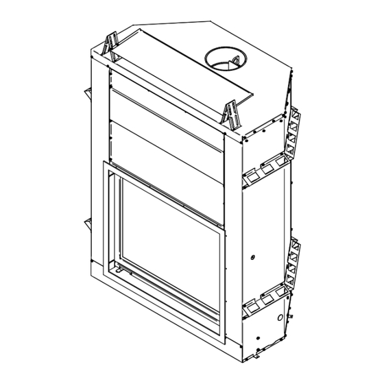
Installation of Spacers and Heat Shield To complete the fireplace, spacers and heat shield must be secured to the top of the appliance. These parts are required to maintain proper clearances to combustible materials. You will find the spacers, heat shield and screws in the firebox (see Figure 2 and 3). Figure 3 Figure 2 Heat shield (1X) -
Page 9: Refractory Panels Installation
Refractory Panels Installation Fire Baffles Installation Your fireplace FP7D contains two fire baffles. In order to protect them during transportation, the small fire baffle (D) is located at the bottom of the combustion chamber, while the largest (E) is in the box in front of your fireplace door. Note that in order to install the small fire baffle... - Page 10 For the installation of the biggest fire baffle (B), it must be positioned as shown in Figure 3.3 B and lean against the front of the chimney throat. Follow these steps to install the fire baffles: 1. To install the first fire baffle (D), hold it in your hands with the narrowest part towards the back of the unit (Figure 3.3 A).
- Page 11 Figure 3.3 C Figure 3.3 D Figure 3.3 E Figure 3.3 F Figure 3.3 G...
-
Page 12: Locating The Fp7D Antoinette Wood Fireplace
Locating the FP7D Antoinette Wood Fireplace A. The best location to install your fireplace is determined by considering the location of windows, doors, and the traffic flow in the room where the fireplace is located, allowing space in front of the unit for the hearth extension and the mantel, and taking into consideration the location of the outside air kit and chimney. -
Page 13: Heart Extension Requirements
Heart Extension Requirements The hearth extension floor area (see (A) on Figure 10) must extend at least 16" (40 cm) in front and at least 8" (20 cm) on each side of the door opening (see Figures 8 and 10). The joint between the hearth extension and the fireplace hearth needs to be made of non-combustible material such as sheet metal or sand-cement grout (not included) as shown on Figure 11. -
Page 14: Framing, Facing, Mantel, And Combustible Shelf
Figure 11 Framing, Facing, Mantel, and Combustible Shelf 3.1.2 Framing The construction of the framing, facing, and mantel must be in accordance with the standards and the following illustrations (Figures 12 to 18): A. Frame the fireplace using 2" × 3" (5 cm x 8 cm) or heavier lumber. WARNING: COMBUSTIBLE FRAMING MATERIAL CANNOT BE USED IN THE SPACE DIRECTLY ABOVE THE FIREPLACE, EXCEPT FOR THE STUDS ABOVE THE FACING THAT SUPPORT THE FACING... - Page 15 B. Frame the fireplace with vertical studs on each side of the fireplace running from floor to ceiling (see Figure 15). Position the studs back from the front edge of the fireplace, leaving a space the thickness of the facing material so that the facing can be installed flush with the fireplace facing (within limitations of Figure 15).
- Page 16 Figure 12 (b) CLEARANCES* 3" (76 mm) maximum 8" (203 mm) minimum 20" (508 mm) minimum *The fireplace can be installed against one of the walls in the room, respecting minimum value (B) from door opening. If the fireplace has a wall built against one side of the fireplace, the other sidewall must respect minimum value (C) from door opening.
- Page 17 Figure 13 Figure 14...
- Page 18 Figure 15 Figure 16...
- Page 19 Figure 17 Insulated chase construction...
- Page 20 Spacers must be installed Figure 18...
-
Page 21: Installing A Television Above A Fireplace
3.1.4 Installing a television above a fireplace Installing a television above a fireplace has become increasingly popular; however, the area above any fireplace gets hot and most TV manufacturers recommend against placing their products near a heat source. If you install a television above this fireplace, SBI accepts no responsibility for damage or injuries. - Page 22 Facing With the Narrow Overlap Figure 19...
- Page 23 Facing With the Masonry Trim Figure 20...
-
Page 24: Combustible Shelf
Figure 21 CAUTION: DO NOT SCREW IN THE HACHURED ZONE (See Figure 21) 3.1.6 Combustible Shelf To install any combustible shelf, refer to Figure 22 for a safe installation. For example, a shelf with a 6" depth (152 mm) must be installed at least 46" (127 cm) from the base of the fireplace. Different shelf dimensions are listed in the table below and in Figure 22 in order to facilitate installation. - Page 25 SHELF POSITIONING SHELF DIMENSION SHELF POSITION 6" / 152 mm 46" / 1168 mm 8" / 203 mm 48" / 1219 mm 10" / 254 mm 50" / 1270 mm 12" / 305 mm 52" / 1321 mm Figure 22...
- Page 26 Figure 23...
-
Page 27: Fresh Air Kit
Fresh Air Kit During operation, the fireplace requires fresh air for combustion and draws air out of the house. It may starve other fuel burning appliances such as gas or oil furnaces. As well, exhaust fans may compete for air, causing negative pressure in the house, resulting in smoke entering the house from the fireplace. - Page 28 Figure 24 Figure 25 Perform an opening in the exterior wall according to the size of the wall termination. From outside, place the outside air inlet cap in the hole (open side down) and fasten the register to the wall, with screws as shown. Place the insulated pipe over the register tube and over the fireplace outside air connector (see Figure 25).
-
Page 29: Installation Of A Gas Lighter
Installation of a gas lighter We have tested this fireplace with a gas lighter. The input of the gas lighter did not exceed 27,000 BTU/h. Therefore, when this maximum input is not exceeded, the temperatures reached by the fireplace are within its safety requirements. Please note that other building code requirements may apply. -
Page 30: Masonry Trim
1. Once the fireplace is fully installed, push the faceplate (C) against the non combustible material, which must be installed on the front of the fireplace. 2. Secure the faceplate (C) to the fireplace with 4 screws (B) supplied with the fireplace. Always make sure the faceplate is squared to the fireplace. - Page 31 Figure 28.1 Masonry Trim 1. Once the fireplace is fully installed, press the masonry trim (A) against the fireplace (the longest side towards the bottom going inside the fireplace). 2. Secure the masonry trim (A) to the fireplace with the screws (B) supplied with the fireplace.
-
Page 32: Door Alignment
Door Alignment To adjust glass door 1. Move the screen door completely to the top. 2. Move down the glass door to the bottom. 3. Unscrew the two bolts (A) which are located on the lower left of the door (See Figure 29). 4. -
Page 33: Suitable Chimneys
Suitable Chimneys This wood fireplace may be connected to either a factory-built metal or a masonry chimney. Whether metal or masonry, the chimney must have a number of characteristics to be suitable. To be suitable, a factory-built metal chimney must comply with UL 103HT (U.S.A.), ULC S629 (Canada) or ULC S-604 (Canada). - Page 34 TABLE 1 - LISTED CHIMNEYS FOR YOUR FP7D ANTOINETTE WOOD FIREPLACE CHIMNEY INNER BRAND TYPE MANUFACTURER DIAMETER Olympia Chimney / Ventis 1" Solid Pack 8" (20 cm) SBI Venting Division SBI Venting division Nexvent 1" Solid Pack 8" (20 cm)
-
Page 35: Rafter Protection
4.1.1 Rafter protection Rafter protectors, at the roof level, must be installed with this unit, if the chimney is enclosed at the attic level. Rafter protectors must be made of 22 ga or more galvanized steel and must have at least the dimension presented on the following diagram: WARNING: IF THE MALE NOZZLE "HATCHED AREA (A)"... -
Page 36: Chimney Installation Notes
Installations, which are located on lower floors in the house, such as in a basement, in combination with outside chimney, are especially prone to flow reversal. 2. The FP7D ANTOINETTE is listed only with chimney systems described in table 1. 3. A chimney venting a fireplace shall not vent any other appliance. - Page 37 Figure 30a Figure 3b...
- Page 38 12. When you build a chase enclosure for chimney sections above the roof, the chimney must extend at least 3 ft. (92 cm) above the chase enclosure and at least 2 ft. (61 cm) higher than any wall, roof or building within 10 ft. (3.1 m) of it. See Figure 31a and 31b to determine the configuration that applies to your roof (flat or sloped roof and the distance between the chimney and the highest point of the roof and/or the nearest chimney).
-
Page 39: Chimney Installation Instructions
Chimney Installation Instructions 1. Cut and frame the holes in the ceiling, floor and roof where the chimney will pass. Use a plumb bob to line up the center of the holes. Make sure that the size of the floor and ceiling holes are in accordance with the chimney manufacturer’s instructions. -
Page 40: Offset Chimney Installation Instructions
Figure 33 Offset Chimney Installation Instructions TABLE 3 – THE MINIMUM SYSTEM HEIGHT WHEN USING ELBOWS IS: Fireplace model FP7D ANTOINETTE WOOD FIREPLACE Chimney model All models listed in Table 1 Vertical installation 15 ft. (4.6 m) * Two (2) elbows 20 ft. - Page 41 After reaching the location requiring the elbow, proceed as follows: 1. Install the first elbow; turn it in the required direction. Secure it to the chimney according to the chimney manufacturer’s instructions. In many cases, it is recommended to secure connections with three (3) ½"...
-
Page 42: Angled Radiation Shield
Figure 35 Angled Radiation Shield When passing through a combustible wall with the chimney at a 30° or 45° angle (30° or 45° in Canada and 30° only in the USA), an angled radiation shield provided by the chimney manufacturer must be installed. Only one is required. Follow the chimney manufacturer’s installation instructions. -
Page 43: Chimney Support Installation
Chimney Support Installation 4.1.2 Universal Roof Support This support has three possible uses: 1. It must be used on a roof to support the chimney. 2. It may be used on a floor, ceiling or roof above an offset to support the chimney above the offset. - Page 44 For installations where more than one chimney is located in the same chase or within the same area, we suggest that their terminations be separated by at least 16" (410 mm) horizontally, and 18" (460 mm) vertically. This separation is to prevent smoke migrating from one chimney to another (see Figure 37).
-
Page 45: Installation Instructions For Masonry Application
Installation Instructions for Masonry Application WARNING: BEFORE STARTING THE INSTALLATION, THE MASONRY CHIMNEY MUST BE INSPECTED BY A QUALIFIED CHIMNEY SWEEPER. The following requirements must be respected: 1. The chimney must be absolutely clear of any soot residue or creosote. Check for cracks, loose or missing bricks that could inhibit correct installation of the liner. -
Page 46: Fuel
PART B - OPERATION AND MAINTENANCE 5. Fuel The FP7D ANTOINETTE WOOD FIREPLACE is designed to work best when fuelled with seasoned cordwood. Use solid wood or processed solid fuel fire logs only. Hardwoods are preferred to softwoods since the energy content of wood is relative to its density. Hardwoods will result in a longer burning fire and less frequent refuelling. -
Page 47: Operating The Fp7D Antoinette Wood Fireplace
6. OPERATING THE FP7D ANTOINETTE WOOD FIREPLACE Inside the firebox of your unit, you will find the handle that allows you to open the doors of your fireplace. Simply insert into the opening provided for this purpose at the bottom left of the glass door and at the bottom right of the fire screen door. -
Page 48: Maintaining The Fire
Your FP7D ANTOINETTE WOOD FIREPLACE will work best if a thick bed of hot embers is maintained in the bottom of the firebox and a minimum of two large pieces of seasoned fuel are added. -
Page 49: Air Intake Control And Exhaust Damper
As the fire burns, air goes up the chimney. This air must be replaced through leakage into the house or through the fresh air kit. When operating the FP7D ANTOINETTE WOOD FIREPLACE, open a nearby window temporarily to check if there is adequate air supply replacement. - Page 50 D. Dirty or blocked chimney Check to make sure the chimney is clear and clean. E. Chimney not long enough The minimum system height is 15 feet (4.6m) including the height of the fireplace itself. The chimney must extend at least 3 feet (915 mm) above its point of contact with the roof and at least 2 feet (0.6 m) higher than any roof or wall within 10 feet (3 m) of it.
-
Page 51: Maintaining Your Fp7D Antoinette Wood Fireplace
7. MAINTAINING YOUR FP7D ANTOINETTE WOOD FIREPLACE Creosote – Formation and Need for Removal When wood is burned slowly without a flame, it produces tar and other organic vapours which combined with expelled moisture will form creosote. The creosote vapours condense in the relatively cool chimney flue of a slow-burning fire. -
Page 52: Dealing With A Chimney Fire
Figure 40.1 Figure 40.2 Figure 40.3 Figure 40.4 Dealing With a Chimney Fire Regular chimney maintenance and inspection can prevent chimney fires. If you have a chimney fire, follow these steps: 1. Close the fireplace glass door and the exhaust damper; 2. -
Page 53: Disposal Of Ashes
Disposal of Ashes Ashes should be placed in a metal container with a tight fitting lid. The closed container of ashes should be placed on a non-combustible floor or on the ground, well away from combustible materials pending final disposal. If the ashes are disposed of by burial in soil or otherwise locally dispersed they should be retained in the closed container until all cinders have thoroughly cooled. -
Page 54: Glass Care - Replacement
Figure 42.5 Glass Care – Replacement The glass used in the FP7D ANTOINETTE WOOD FIREPLACE is ceramic glass 5 mm thick having dimensions of: 30 3/4" x 20 3/4" and tested to reach temperatures up to 1400 ºF. If the glass breaks, it must be replaced with one having the same specification. -
Page 55: Glass Care - Cleaning
Figure 43 Glass Care – Cleaning The FP7D ANTOINETTE WOOD FIREPLACE is designed to keep the glass clean under normal operating conditions. To clean the glass, there are a number of specially designed cleaners. Your authorized Valcourt dealer can recommend a suitable cleaner which is available in your area. -
Page 56: Views With Measurements
8. VIEWS WITH MEASUREMENTS VA7FE06... - Page 57 VA7TR...
-
Page 58: Exploded Diagram And Parts List
9. EXPLODED DIAGRAM AND PARTS LIST... - Page 59 IMPORTANT: THIS IS DATED INFORMATION. When requesting service or replacement parts for your stove, please provide the model number and the serial number. We reserve the right to change parts due to technology upgrade or availability. Contact an authorized dealer to obtain any of these parts.
-
Page 60: Valcourt Limited Lifetime Warranty
*Pictures required **Limited to one replacement Shall your unit or a components be defective, contact immediately your VALCOURT dealer. Prior to your call make sure you have the following information necessary to your warranty claim treatment: Nature of the defect and any relevant information Your name, address and telephone number ...
Need help?
Do you have a question about the FP7D and is the answer not in the manual?
Questions and answers