Table of Contents
Advertisement
Quick Links
Advertisement
Table of Contents

Related Manuals for VOLTCRAFT DSP-3010


Summary of Contents for VOLTCRAFT DSP-3010
- Page 1 Single Channel DC Power Supply User Manual DSP-3005 DSP-3010 DSP-6010...
-
Page 2: Table Of Contents
Table of Contents 1. General Safety Requirements ............1 2. Safety Terms and Symbols ..............2 3. Quick Review ..................3 3.1 Panel and Interface ................3 3.1.1 Front Panel ......................3 3.1.2 Rear Panel ......................4 3.1.3 User Interface ......................5 3.2 General Inspection ................5 3.3 Power Inspection ................. -
Page 3: General Safety Requirements
1.General Safety Requirements 1. General Safety Requirements Before use, please read the following safety precautions to avoid any possible bodily injury and to prevent this product or any other connected products from damage. To avoid any contingent danger, ensure this product is only used within the ranges specified. -
Page 4: Safety Terms And Symbols
2.Safety Terms and Symbols 2. Safety Terms and Symbols Safety Terms Terms in this manual (The following terms may appear in this manual): Warning: Warning indicates conditions or practices that could result in injury or loss of life. Caution: Caution indicates the conditions or practices that could result in damage to this product or other property. -
Page 5: Quick Review
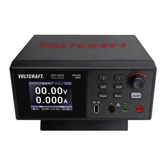
3.Quick Review 3. Quick Review 3.1 Panel and Interface 3.1.1 Front Panel Figure 3- 1 Front Panel Overview (take DSP-6010 as example) Over Voltage Set over voltage protection parameters, press to move Setting Key the cursor when editing parameters Set voltage parameters, press to move the cursor when Voltage Key editing parameters Set current parameters, press to move the cursor when... -
Page 6: Rear Panel
3.Quick Review Button light instruction On/Off key:The key lights up when the channel turns on. 3.1.2 Rear Panel Figure 3- 2 Rear Panel Overview (take DSP-6010 as example) AC Power Input AC power input interface. Jack 2 Fuse Power fuse. 3 Power Button Turn on/off the instrument. -
Page 7: User Interface
3.Quick Review 3.1.3 User Interface Figure 3- 3 User Interface 3.2 General Inspection After you get a new power supply, it is recommended that you should make a check on the instrument according to the following steps: 1. Check whether there is any damage caused by transportation. If it is found that the packaging carton or the foamed plastic protection cushion has suffered serious damage, do not throw it away first till the complete device and its accessories succeed in the electrical and... -
Page 8: Power Inspection
3.Quick Review If it is found that there is damage to the appearance of the instrument, or the instrument can not work normally, or fails in the performance test, please get in touch with our distributor responsible for this business or our local offices. - Page 9 3.Quick Review The following steps check basic current functions with a short across the power supply's output: Connect a short across (+) and (-) output terminals with an insulated test lead on this channel. Use a wire size sufficient to handle the maximum current.
-
Page 10: Panel Operation
4.Panel Operation 4. Panel Operation 4.1 Turn On/Off the Channel Output Press the On/Off key to turn on/off the channel; 4.2 Set the Output Voltage/Current In the channel setting area, press the key to move the gray cursor between different positions of the voltage/current value. After pressing the output voltage/current setting value, turn the knob to change the value of the current cursor, and press the knob or press the key to move the... -
Page 11: Memory Key Shortcut Settings
4.Panel Operation 4.4 Memory key shortcut settings Press the Memory key on the front panel to store 4 sets of channel parameters M1, M2, M3, and M4 respectively for quick output. 4.4.1 Quick output To output a set of parameters from M1 to M4, follow these steps: (1) Press Memory key on front panel, the shortcut interface will display. -
Page 12: Set List Waveform Output
4.Panel Operation voltage protection / over current protection value. (4) Turn the knob to change the value of the current cursor, press the knob or press the V / I / OVP / OCP key to move the cursor. 4.5 Set List Waveform Output The user can edit and output the waveform. -
Page 13: List Waveform Output
4.Panel Operation Memory move the cursor position; short press the function key on the front panel to exit the parameter setting status; (5) In the non-parameter setting state, press the knob for 3 seconds to confirm, enter the "List Waveform Output Mode", and at the same time, switch back to the main interface;... -
Page 14: Set Automatic Output At Power-On
4.Panel Operation 4.6 Set Automatic Output at Power-on The user can turn on or turn off the "automatic output at power-on" function by On/Off pressing and holding the function key for 3 seconds. (1) The steps are as follows. The user can turn on or turn off the "automatic output at power-on"... - Page 15 4.Panel Operation number or curve. Number Press the Display function key to set the display mode to Number. When the power supply is powered on, the default display mode is Curve. Curve Press the Display function key to set the display mode to Curve.
-
Page 16: Troubleshooting
5.Troubleshooting 5. Troubleshooting 1. The instrument is powered on but no Display. Check if the power is connected properly. Check if the fuse which is below the AC Power socket is used appropriately and in good condition (the cover can be pried open with a straight screwdriver). -
Page 17: Technical Specification
Input Frequency 45~65Hz Input Parameter (220Vac±15%) Input Voltage Range 187~253Vac Input active power 300W DSP-3005 400 VA Max Input maximum apparent DSP-3010 power 800 VA Max DSP-6010 DSP-3005 ≤1.4A Full Load Input Current DSP-3010 ≤2.8A DSP-6010 DSP-3005 ≤100mA... - Page 18 6.Technical Specification DSP-3010 Max output power 300W DSP-6010 Efficiency (220Vac, rated load) Regulation(CV) Load ≤30mV Line ≤20mV Regulation(CC) Load ≤30mA Line ≤20mA Ripple & Noise (Noise bandwidth 20MHz, ripple bandwidth 1MHz, connect 10uF electrolytic capacitor in parallel with 0.1uF ceramic...
- Page 19 6.Technical Specification (50%~100% rated load) Protective function DSP-3005 0~31V DSP-3010 0~31V DSP-6010 0~61V DSP-3005 0~5.1A DSP-3010 0~10.1A DSP-6010 0~10.1A 85℃ Temperature coefficient of output Voltage 100ppm/℃ Current 200ppm/℃ Temperature coefficient of readback value Voltage 100ppm/℃ Current 200ppm/℃ Display Display Type 2.8inches color LCD...
-
Page 20: Appendix
7.Appendix 7. Appendix 7.1 Appendix A: Accessories (The accessories subject to final delivery. ) Power cord x 1 User manual EN x 1 User manual DE x 1 Safety Hintsheet x 1 Fuse x 1 CD ROM x 1 USB Cable x 1 7.2 Appendix B: General Care and Cleaning General Care Do not store or leave the instrument where the liquid crystal display could be...
Need help?
Do you have a question about the DSP-3010 and is the answer not in the manual?
Questions and answers