Chapters
Table of Contents

Related Manuals for Hydac FCU1315


Summary of Contents for Hydac FCU1315
- Page 1 FCU1315 FluidControl Unit Operating and Maintenance Instructions English • (translation of original instructions) Document No. : 4168086b • 1/17/2019 Follow these instructions for proper and safe use. Keep for future reference.
-
Page 2: Documentation Representative
Dipl.Kfm. Wolfgang Haering Tab. 1: Impressum 1.1 Documentation Representative The contact data of the person authorized with the documenta- tion is: Mr. Günter Harge c/o HYDAC International GmbH, Industriegebiet, 66280 Sulzbach / Saar Germany Phone: +49 6897 509 1511 Fax: +49 6897 509 1394 E-mail: guenter.harge@hydac.com... -
Page 3: Table Of Contents
1 Imprint ........................ 2 Documentation Representative................ 2 2 General ........................ 7 Warranty...................... 7 © HYDAC FILTER SYSTEMS GMBH, 2018............ 7 Using this manual..................... 8 3 Safety information .................... 10 Signal words and their meaning in the safety information and instructions ... 11 Design of Warning - / General Safety Information ......... - Page 4 SAVE – Saving settings / data ............ 76 Select the operating modes / measurement method according to the pressure involved ...................... 77 7.3.1 Measuring from unpressurized containers ........ 78 7.3.2 Measuring up to max. 45 bar / 650 psi with hydraulic fluids .... 82 BeWa FCU1315 4168086b en lq...
- Page 5 FCU flushing .................... 127 Cleaning the FCU.................. 130 10 Finding / rectifying errors.................. 131 11 Removing / Disposal ..................... 138 12 Attachment ...................... 139 12.1 Finding spare parts / accessories .............. 139 12.1.1 Finding accessories ................. 141 BeWa FCU1315 4168086b en lq...
- Page 6 Table of Contents HYDAC FILTER SYSTEMS GMBH 12.2 Finding a Customer Service team.............. 144 12.3 EC declaration of conformity ................ 145 Glossary ........................ 151 Index ........................ 152 BeWa FCU1315 4168086b en lq...
-
Page 7: General
Delivery. They are made available to you at the conclusion of the contract at the latest. You will also find these under www.hydac.com -> General Terms and Conditions (T&C). 2.2 © HYDAC FILTER SYSTEMS GMBH, 2018 Distributing and copying this document and utilizing and dis- closing its content is not permitted, except where this has been agreed upon explicitly. -
Page 8: Using This Manual
The document no. with the index (4) is meant for identifying and reordering the manual. The index is incremented every time the manual is revised or changed. 8 / 156 BeWa FCU1315 4168086b en lq... - Page 9 The manual contains a table of contents, a list of tables and figures, an index and a glossary. You will find the following symbols in the manual as additional details: Tip for handling the product Required tools BeWa FCU1315 4168086b en lq 9 / 156...
-
Page 10: Safety Information
Any residual hazards are indi- cated by the general safety information and are described in this manual. Observe all safety and warning instructions attached to the product and keep them always complete and easily legible. 10 / 156 BeWa FCU1315 4168086b en lq... -
Page 11: Signal Words And Their Meaning In The Safety Information And Instructions
NOTICE NOTICE – The signal word indicates a hazardous situation with a high level of risk, which, if not avoided, will result in damage to property. BeWa FCU1315 4168086b en lq 11 / 156... -
Page 12: Design Of Warning - / General Safety Information
These signs are listed for all safety information and instructions in these operating instructions which indicate particular haz- ards to persons, property or the environment. Danger point warning Dangerous electrical voltage warning 12 / 156 BeWa FCU1315 4168086b en lq... - Page 13 Specialist personnel - Mechanic Such persons have specific specialist training and several years' work experience. They are able to assess and perform the work assigned to them, they are also able to recognize potential hazards. BeWa FCU1315 4168086b en lq 13 / 156...
- Page 14 These signs are listed for the general safety instructions in these operating instructions, for example, which indicate a par- ticular danger to persons, property or the environment. Danger due to operating pressure 14 / 156 BeWa FCU1315 4168086b en lq...
-
Page 15: Observe Regulatory Information
Maintain a minimum safe distance from electrical components. For a mains voltage of up to 1000 V, the minimum safe dis- tance is 1 m. Fig. 2: Fire protection class B Fig. 3: Minimum distance for fire fighting BeWa FCU1315 4168086b en lq 15 / 156... -
Page 16: Overview
– 2 … 350 mm²/s / 33 … 1622 Sus – Automatic measurement and display of cleanliness ratings in accordance with: – ISO 4406; NAS 1638 – ISO 4406; SAE AS 4059 (D) – Measurement accuracy +/- ½ ISO code in the calibrated range 16 / 156 BeWa FCU1315 4168086b en lq... - Page 17 – Operating pressure without high-pressure adapter max. 45 bar / max. 650 psi, Operating pressure with high-pressure adapter max. 345 bar / max. 5000 psi – Integrated pump for supplying the FCU with the fluid to be analyzed BeWa FCU1315 4168086b en lq 17 / 156...
-
Page 18: Counting Contaminant Particles Optically (Light Blockade Procedure)
Fig. 4: Light blockade procedure 1 Light source 2 Contaminant particle 3 Photo detector 18 / 156 BeWa FCU1315 4168086b en lq... -
Page 19: Fig. 5 Signal Amplitudes
The signal height or amplitude reflects the particle size. Thresholds are used to classify the particle sizes >2-5 µm, >5-15 µm, >15-25 µm, >25 µm or >4 µm , >6 µm >14 µm , >21 µm time Fig. 5: Signal amplitudes BeWa FCU1315 4168086b en lq 19 / 156... -
Page 20: Proper/Designated Use
Operation with diesel fuel only with the equipotential bond- ing cable connected. u Observe all the instructions contained in these Operating and Maintenance Instructions. u Comply with all inspection and maintenance work. 20 / 156 BeWa FCU1315 4168086b en lq... -
Page 21: Periodic Intermittent Duty - Operating Mode S3
, followed by the cooling-down phase (downtime) t . The relative duty cycle is 40% in relation to a useful life of 10 min- utes. BeWa FCU1315 4168086b en lq 21 / 156... -
Page 22: Fig. 6 Operating Mode S3 - Periodic Intermittent Duty
4 | Overview HYDAC FILTER SYSTEMS GMBH Nominal power, operating mode S3 t time Period Operation Cooling phase (downtime) °C (°F) Temperature Fig. 6: Operating mode S3 – Periodic intermittent duty 22 / 156 BeWa FCU1315 4168086b en lq... -
Page 23: Improper Use Or Use Deviating From Intended Use
Operation with diesel fuel permitted only with connected equipotential bonding:voltage equalizing cable with the voltage equalizing cable. u Modifications to the product made by the user or pur- chaser. u Operation in potentially explosive atmospheres. u Continuous operation. BeWa FCU1315 4168086b en lq 23 / 156... -
Page 24: Checking The Scope Of Delivery
- USB memory stick, with Operating and Mainte- nance Instructions (PDF file) in additional lan- guages Tab. 3: Scope of delivery A USB Bluetooth adapter for the PC is a free gift and is not part of the delivery. 24 / 156 BeWa FCU1315 4168086b en lq... -
Page 25: Decoding The Model Code Label
Fig. 7: Type label Item -> Description -> Type label for FCU -> Model code; for details, see Model Code [} 27] -> Information regarding permis- sible flash point of the fluids to be tested BeWa FCU1315 4168086b en lq 25 / 156... - Page 26 Permissible pressure at port OUTLET Temperatures -> Temperature specifications -> Permissible oil temperature range Ambient -> Permitted ambient tempera- ture range Power -> Power consumption Voltage -> Voltage Current -> Current consumption 26 / 156 BeWa FCU1315 4168086b en lq...
-
Page 27: Model Code
Integrated sensor AquaSensor AS 1000 (only 131x) without Power supply adapter 100 ... 240 V AC / 50/60 Hz / 1-phase / 5000 mA (Europe, USA/Canada, UK, Australia, Japan) Fig. 8: Model Code BeWa FCU1315 4168086b en lq 27 / 156... -
Page 28: Technical Data
10 … 300 Seconds urable Tab. 4: Contamination sensor Hydraulic data Suitable Fluids Mineral oil or raffinate based on min- eral oil Hydraulic connections INLET Test connector type 1604 OUTLET DN7 nipple socket 28 / 156 BeWa FCU1315 4168086b en lq... -
Page 29: Tab. 5 Hydraulic Data
Current consumption ≤ 4 A Operating mode S3, periodic intermittent duty as per DIN EN 60034-1 / DIN VDE 0530 part 1 relating to a useful life of 10 minutes. Relative duty cycle 40 % BeWa FCU1315 4168086b en lq 29 / 156... -
Page 30: Tab. 6 Electrical Data
0 … 45 °C / 32° … 113 °F perature range Permitted storage tem- -40 … 80 °C / -40 … 176 °F perature range Permitted relative hu- max. 90%, non-condensing midity Weight when empty ≈ 13 kg Tab. 7: General data 30 / 156 BeWa FCU1315 4168086b en lq... -
Page 31: Dimensions
HYDAC FILTER SYSTEMS GMBH Overview | 4 4.7 Dimensions The FCU has the following dimensions. Fig. 9: Dimensions All dimensions in mm. BeWa FCU1315 4168086b en lq 31 / 156... -
Page 32: Hydraulic Circuit
1 INLET, gauge port type 1604 2 Suction strainer, 400 µm 3 Gear pump 4 Electric motor 5 Pressure relief valve 6 Contamination sensor 7 Counter balance valve 8 AquaSensor 9 OUTLET, DN7 quick coupling nipple 32 / 156 BeWa FCU1315 4168086b en lq... -
Page 33: Opening / Closing The Case
Open the FCU case by releasing the two clips. Fig. 11: Opening the FCU case Close the FCU using both clips. Make sure that these audibly snap into place. Fig. 12: Closing the FCU case BeWa FCU1315 4168086b en lq 33 / 156... -
Page 34: How It Works
(9) OUTLET and is routed by the return hose to a pressurized tank. Fig. 13: Hydraulic circuit The electronic evaluation module monitors: – the function of the contamination sensor – the oil flow – the function of the AquaSensor 34 / 156 BeWa FCU1315 4168086b en lq... - Page 35 The status display will indicate an error in the event that one occurs. The evaluation module will recognize when the cause of error has been corrected, and the unit will reset automati- cally and resume the measurement operation. BeWa FCU1315 4168086b en lq 35 / 156...
-
Page 36: Transporting / Storing The Fcu
Let the FCU and the hoses cool down. To prepare the FCU for transport, observe the following se- quence: 1. Undo the measurement hose from the measurement point. 2. Use the switch to turn the internal pump off. 36 / 156 BeWa FCU1315 4168086b en lq... - Page 37 3. Remove the USB stick, should it be inserted. 4. Close the USB socket with the corresponding cover. 5. Remove the hose by turning counterclockwise from the INLET connection of the FCU. BeWa FCU1315 4168086b en lq 37 / 156...
- Page 38 8. Close the FCU using both clips. Make sure that both clips audibly snap into place. 9. Stow the hose and the power supply in the bag. ð The FCU is ready for transport. 38 / 156 BeWa FCU1315 4168086b en lq...
-
Page 39: Transporting The Fcu
Transporting / storing the FCU | 5 5.2 Transporting the FCU Transport the FCU only when it is in closed position; carry it flat or by the handle. Fig. 14: Transporting the FCU BeWa FCU1315 4168086b en lq 39 / 156... -
Page 40: Storing The Fcu
Store the FCU closed and in a horizontal position in a dry, clean place. If stored in a vertical position, the FCU must not be exposed to any shaking or vibration. Fig. 15: Storing the FCU 40 / 156 BeWa FCU1315 4168086b en lq... -
Page 41: Putting The Fcu Into Operation
). Connect the other end with the voltage source. 2. Once the FCU is supplied with voltage, the display will show "HYDAC FCU 1###" in ticker format. Afterwards, the firmware version will be shown for 2 seconds. The internal sensors will be checked after that. -
Page 42: Fig. 17 Disconnecting The Power Supply
6 | Putting the FCU into operation HYDAC FILTER SYSTEMS GMBH Fig. 17: Disconnecting the power supply 42 / 156 BeWa FCU1315 4168086b en lq... -
Page 43: Plug In/Detach Return Hose
Make sure that the quick-action coupling is firmly seated. Fig. 18: Plug in return hose Put the other end of the return hose into a depressurized con- tainer or tank. Fig. 19: Detach return hose BeWa FCU1315 4168086b en lq 43 / 156... -
Page 44: Configuring / Setting Fcu (Powerup)
CALIB – Selecting the calibration type [} 49] DFAULT – Reset to default settings [} 50] CANCEL - Cancel [} 51] SAVE – Saving settings / data [} 52] Tab. 8: PowerUp Menu Press the button to switch to a sub-menu. 44 / 156 BeWa FCU1315 4168086b en lq... -
Page 45: Dat.tim - Setting The Date/Time
=> year / month / day. The time uses the 24-hour format: => hour / minute. Fig. 20: DAT.TIM – Setting the date/time Use the following buttons to set the date and time: Change the values. Change the position. Confirm the changes. Cancel and back. BeWa FCU1315 4168086b en lq 45 / 156... -
Page 46: Adress - Set Bus Address
Fig. 21: ADRESS - Set bus address Use the following buttons to set the address: Change the values. Change the position. Confirm the changes. Cancel and back. The factory setting of the bus address is: 46 / 156 BeWa FCU1315 4168086b en lq... -
Page 47: Del.mem - Deleting The Measurement Report Memory
Before deletion, back up all of the measure- ment records on the USB memory stick. Fig. 22: DEL.MEM – Deleting the measurement report memory Push the following buttons for deletion: Confirm the changes. Cancel and back. BeWa FCU1315 4168086b en lq 47 / 156... -
Page 48: M.time - Set Measuring Time
Fig. 23: M.TIME - Set measuring time Use the following buttons to set the duration of the measure- ment: Change the values. Change the position. Confirm the changes. Cancel and back. The factory setting is: 48 / 156 BeWa FCU1315 4168086b en lq... -
Page 49: Calib - Selecting The Calibration Type
– The calibration type ISO.SAE is based on ISO4406 / SAE. – The calibration type ISO.NAS is based on ISO4406 / NAS. Fig. 24: CALIB - Calibration selection Use the following buttons: Change the values. Confirm the changes. Cancel and back. BeWa FCU1315 4168086b en lq 49 / 156... -
Page 50: Dfault - Reset To Default Settings
Factory settings [} 53]. Fig. 25: DFAULT - Reset to default settings Use the following buttons: Change the values. Change the position. Confirm the changes. Cancel and back. 50 / 156 BeWa FCU1315 4168086b en lq... -
Page 51: Cancel - Cancel
6.3.7 CANCEL - Cancel Use CANCEL CANCEL to discard all changes and exit the menu. Fig. 26: CANCEL - Cancel Use the following buttons: Change the position. Confirm the changes. Cancel and back. BeWa FCU1315 4168086b en lq 51 / 156... -
Page 52: Save - Saving Settings / Data
Use SAVE to store all of your changes and exit the menu. Fig. 27: SAVE – Saving settings / data Use the following buttons: Change the position. Confirm the changes. Cancel and back. 52 / 156 BeWa FCU1315 4168086b en lq... -
Page 53: Factory Settings
[} 49] Bluetooth Code 0000 Connecting/Linking the FCU via Bluetooth [} 109] Tab. 9: Factory settings The names of the measurement locations as well as all other settings are not affected by the reset. BeWa FCU1315 4168086b en lq 53 / 156... -
Page 54: Connecting The Equipotential Bonding
The permissible types of diesel have a low conductivity. This means that static charges can come about during flows through tubes or pipes which, in the event of an uncontrolled electrostatic discharges can become an ignition source for ex- plosive mixtures. 54 / 156 BeWa FCU1315 4168086b en lq... -
Page 55: Selecting The Measurement Location
Select the measurement location so that the sample measured comes from a turbulent location, with a good flow. For exam- ple: on a pipe bend (A). This ensures that a typical sample is analyzed. BeWa FCU1315 4168086b en lq 55 / 156... - Page 56 If the FCU is installed near the measurement point (B), avoid delayed measurement results and sedimentation (particle de- posits in the line). While installing the inlet hose INLET, make sure that no siphon (C) results. 56 / 156 BeWa FCU1315 4168086b en lq...
-
Page 57: Operation
3 Fluid temperature display 4 ON / OFF switch for the internal pump 5 3-pole connection for 24 V DC supply voltage 6 Data interface DATA 7 Connection OUTLET 8 Connection INLET 9 USB interface with cover BeWa FCU1315 4168086b en lq 57 / 156... - Page 58 10 Socket for connecting the voltage equalizing cable 11 Voltage equalizing cable 14 Fastener for the OUTLET connection when the case is closed 15 Holding-down device 16 Bag for hoses and accessories - Bluetooth interface 58 / 156 BeWa FCU1315 4168086b en lq...
-
Page 59: Reading The Display And Operating The Keyboard
Measured variable Indicates the respective measured variable pre- sented in the display, e.g.: Service variable Indicates the respective service variable presented in the display, e.g.: BeWa FCU1315 4168086b en lq 59 / 156... -
Page 60: Tab. 10 Keyboard Overview
Cancel (no values changed). Change values at the lowest levels (If you are at the lowest menu level, the display will flash). Scroll through the display. Scroll through the menu. Select positions. Tab. 10: Keyboard overview 60 / 156 BeWa FCU1315 4168086b en lq... -
Page 61: Scrolling Through The Display
2 Finding / rectifying errors [} 131] 7.1.2 Scrolling through the display Depending on the selected type of calibration ( in the Power Up menu you can scroll through the following dis- plays using the keys BeWa FCU1315 4168086b en lq 61 / 156... -
Page 62: Tab. 11 Displays With Iso.sae
The following displays are available: Display Description 3-digit ISO code SAE Class A SAE Class B SAE Class C SAE Class D SAE Max. Flow status LED current in % Tab. 11: Displays with ISO.SAE 62 / 156 BeWa FCU1315 4168086b en lq... -
Page 63: Tab. 12 Displays With Iso.nas
3-digit ISO code NAS 2-5 µm channel NAS 5-15 µm channel NAS 15-25 µm channel NAS > 25 µm channel NAS Max. LED current in % Flow status Tab. 12: Displays with ISO.NAS BeWa FCU1315 4168086b en lq 63 / 156... -
Page 64: Displaying Measured Variables
19.3% water saturation 7.1.3.5 Measured variable – Temperature The integrated AquaSensor continuously measures the fluid temperature. The output as Celsius °C or Fahrenheit °F can be set under . Example: Temperature = 37.8 °C 64 / 156 BeWa FCU1315 4168086b en lq... -
Page 65: Display Service Variables
Flow contains the display indicating whether the flow is in the permissible range. Example: Flow rate = OK 7.1.4.2 Service variable - Drive Display of the light source efficiency (1-100%) with which the ContaminationUnit currently works. Example: Light source effi- ciency = 42% BeWa FCU1315 4168086b en lq 65 / 156... -
Page 66: Operating/Setting Measuring Menu
ED.MPNT – Change name of mea- surement point [} 71] TP.UNIT - Set temperature unit [} 73] CANCEL - Cancel [} 75] SAVE – Saving settings / data [} 76] Tab. 13: Measuring Menu Press the button to switch to a sub-menu. 66 / 156 BeWa FCU1315 4168086b en lq... -
Page 67: Record - Record Measurements
Fig. 30: RECORD – Record measurements Use the following buttons: Change the values. Change the position. Confirm the changes. Cancel and back. Fig. 31: MPNT - xx BeWa FCU1315 4168086b en lq 67 / 156... - Page 68 Select STP.STA to create a new measurement report file in the internal measurement report memory under a new measure- ment point designation. Confirm with the button, after which the display will jump to . Confirm once more by pressing the key. 68 / 156 BeWa FCU1315 4168086b en lq...
- Page 69 HYDAC FILTER SYSTEMS GMBH Operation | 7 Fig. 33: Restarting the STP.STA - measurement report Use the following buttons: Change the values. Change the position. Confirm the changes. Cancel and back. BeWa FCU1315 4168086b en lq 69 / 156...
-
Page 70: Memory - Displaying Free Measurement Report Memory
Check the measurement report data memory regularly (depending on frequency of use) for free memory space. Fig. 34: MEMORY – Displaying the free measurement report memory Use the following buttons: Confirm the changes. Cancel and back. 70 / 156 BeWa FCU1315 4168086b en lq... -
Page 71: Ed.mpnt - Change Name Of Measurement Point
VATOR, CRANE02, etc. Fig. 35: Changing the ED.MPNT - measurement point designation Push the following buttons for deletion: Change the values. Change the position. Confirm the changes. Cancel and back. Change the values. BeWa FCU1315 4168086b en lq 71 / 156... - Page 72 The empty space is located between 9 and A and can be ad- justed only from the 6th position to the left. This means it is possible to enter a measurement point designation with less than six characters. 72 / 156 BeWa FCU1315 4168086b en lq...
-
Page 73: Tp.unit - Set Temperature Unit
Fig. 36: TPUNIT – Setting the temperature unit Use the following buttons: Change the values. Change the position. Confirm the changes. Cancel and back. Fig. 37: TPUNIT – setting degrees Celsius Change the values. BeWa FCU1315 4168086b en lq 73 / 156... - Page 74 7 | Operation HYDAC FILTER SYSTEMS GMBH Change the position. Confirm the changes. Cancel and back. 74 / 156 BeWa FCU1315 4168086b en lq...
-
Page 75: Cancel - Cancel
7.2.5 CANCEL - Cancel Use CANCEL CANCEL to discard all changes and exit the menu. Fig. 38: CANCEL - Cancel Use the following buttons: Change the position. Confirm the changes. Cancel and back. BeWa FCU1315 4168086b en lq 75 / 156... -
Page 76: Save - Saving Settings / Data
Use SAVE to store all of your changes and exit the menu. Fig. 39: SAVE – Saving settings / data Use the following buttons: Change the position. Confirm the changes. Cancel and back. 76 / 156 BeWa FCU1315 4168086b en lq... -
Page 77: Select The Operating Modes / Measurement Method According To The Pressure Involved
Measuring up to max. 14 … 650 psi 45 bar / 650 psi with hydraulic flu- ids [} 82] 15 … 345 bar / Measuring in the range 217 … 5000 psi 5 to 345 bar / 217 to 5000 psi with oil [} 88] Tab. 14: Selecting the operating mode / measurement method BeWa FCU1315 4168086b en lq 77 / 156... -
Page 78: Measuring From Unpressurized Containers
7.3.1 Measuring from unpressurized containers To measure permissible oil or diesel fuel from depressurized containers, proceed as follows: Required hoses: -Return hose -Suction tube (A) or suction hose (B) + hose adapter 78 / 156 BeWa FCU1315 4168086b en lq... - Page 79 HYDAC FILTER SYSTEMS GMBH Operation | 7 Fig. 40: Operating mode - Measurement at 0 bar with suction tube (A) BeWa FCU1315 4168086b en lq 79 / 156...
- Page 80 For an initial test without priming the FCU and hoses, you need ≥ 300 ml of fluid. Make sure that the following sequence is observed: ü You have performed all of the steps listed in chapter Putting the FCU into operation [} 41]. 80 / 156 BeWa FCU1315 4168086b en lq...
- Page 81 Place the other end of the suction hose (color: clear transparent) into a depressurized container. ð This completes the hydraulic installation. 2. Switch on the internal pump. ð The FCU will start with the measurement. BeWa FCU1315 4168086b en lq 81 / 156...
-
Page 82: Measuring Up To Max. 45 Bar / 650 Psi With Hydraulic Fluids
Never seal the connection OUTLET. u Put the free end of the OUTLET return hose into an un- pressurized container. u When operating, always observe the permissible operating pressure. Required hoses: -Return hose -High-pressure hose 82 / 156 BeWa FCU1315 4168086b en lq... - Page 83 650 psi, then use the high-pressure adapter. 2. Connect the entry hose (color: black) with the INLET connection of the FCU (1). Rotate the measurement coupling clockwise (2) to the connection and tighten it by hand. BeWa FCU1315 4168086b en lq 83 / 156...
- Page 84 3. Connect the other end of the INLET pressure hose to the measurement point of the system. 4. Switch on the internal pump. ð The hydraulic installation of the FCU is complete. The FCU will start with the measurement. 84 / 156 BeWa FCU1315 4168086b en lq...
-
Page 85: Measuring Diesel Fuel Up To Max. 16 Bar / 232 Psi
Never seal the connection OUTLET. u Put the free end of the OUTLET return hose into an un- pressurized container. u When operating, always observe the permissible operating pressure. Required hoses: -Return hose -High-pressure hose BeWa FCU1315 4168086b en lq 85 / 156... - Page 86 1. Check the pressure at the measurement location. The existing pressure must be within the range of 0 … 16 bar / 0 … 232 psi. WARNING! If the pressure is greater than 16 bar / 232 psi, then a measurement is not permitted. 86 / 156 BeWa FCU1315 4168086b en lq...
- Page 87 3. Connect the other end of the INLET pressure hose to the measurement point of the system. 4. Switch on the internal pump. ð The hydraulic installation of the FCU is complete. The FCU will start with the measurement. BeWa FCU1315 4168086b en lq 87 / 156...
-
Page 88: Measuring In The Range 5 To 345 Bar / 217 To 5000 Psi With Oil
Put the free end of the OUTLET return hose into an un- pressurized container. u When operating, always observe the permissible operating pressure. Required hoses / adapters: Return hose High-pressure hose High-pressure adapter 88 / 156 BeWa FCU1315 4168086b en lq... - Page 89 15 … 345 bar / 217 … 5000 psi. WARNING! If the pressure is greater than 345 bar / 5000 psi, abort the measurement attempt. 2. Screw the high-pressure adapter onto the INLET con- nection of the FCU. BeWa FCU1315 4168086b en lq 89 / 156...
- Page 90 4. Connect the other end of the INLET pressure hose to the measurement point of the system. 5. Switch on the internal pump. ð The hydraulic installation of the FCU is complete. The FCU will start with the measurement. 90 / 156 BeWa FCU1315 4168086b en lq...
-
Page 91: Performing Measurements
2. After the set measurement time, the result is shown on the display, and the status LED lights up green perma- nently. 3. Switch the pump off after 4 minutes. ð The measurement is complete. BeWa FCU1315 4168086b en lq 91 / 156... -
Page 92: Restarting/Resetting
To restart or reset the FCU, remove the power supply to the FCU for 10 seconds. Press the catch (1) on the connector and then pull (2) the con- nector out. Insert the connector into the socket until it audibly snaps in. 92 / 156 BeWa FCU1315 4168086b en lq... -
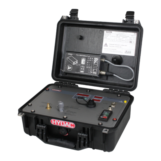
Page 93: Using The Batterypack (Accessory)
(3) during transport. Fig. 45: BatteryPack overview 1 BatteryPack 2 Indexing plunger 3 Mounting rails For operation with the BatteryPack, fit the connector into the socket labeled DC IN of the FCU. BeWa FCU1315 4168086b en lq 93 / 156... - Page 94 7 | Operation HYDAC FILTER SYSTEMS GMBH Fig. 46: BatteryPack in operation 94 / 156 BeWa FCU1315 4168086b en lq...
-
Page 95: Removing / Inserting The Batterypack
Guide the BatteryPack down to the lower stop in the guide rails (2). Release the locking pin (3). A spring will return the lock- ing pin to its original position, thus securing the Battery- Pack. Check the BatteryPack is sufficiently tight/secured. BeWa FCU1315 4168086b en lq 95 / 156... - Page 96 7 | Operation HYDAC FILTER SYSTEMS GMBH 4. Insert the connector into the socket on the BatteryPack. ð The BatteryPack is securely stored and ready for trans- portation or operation. 96 / 156 BeWa FCU1315 4168086b en lq...
- Page 97 Slide the BatteryPack upwards (2). 7. Pull the BatteryPack up and out of the mounting rails. Then insert the connector back into the socket on the BatteryPack. ð The BatteryPack is removed from the FCU. BeWa FCU1315 4168086b en lq 97 / 156...
-
Page 98: Extracting The Internal Measured Value Memory
DATA interface [} 99] USB interface Extracting / copying measure- ment reports via USB interface [} 102] Bluetooth interface Measurement reports via Blue- tooth interface [} 108] Tab. 15: Extracting the measured value memory 98 / 156 BeWa FCU1315 4168086b en lq... -
Page 99: Extracting Measurement Reports Via Data Interface
The FCU has one DATA interface for conveying the measure- ment reports. The DATA interface communicates in the HSI protocol. 7.7.1.1 Pins used on the DATA interface (HYDAC Sensor Interface HSI) The HSI interface has connection plug M12x1, 5-pole, in ac- cordance with DIN VDE 0627. - Page 100 7 | Operation HYDAC FILTER SYSTEMS GMBH 7.7.1.2 Connecting the FCU with CSI-B-2 The FCU can be connected to a PC using the CSI-B-2 kit. Fig. 48: FCU <-> CSI-B-2 100 / 156 BeWa FCU1315 4168086b en lq...
- Page 101 - HMG 510 (with firmware version 2, release 15 or higher) - HMG 3000 (with firmware version 2, release 1 or higher) - HMG 4000 See the operating instructions for the HMG for further details. Fig. 49: FCU<->HMG BeWa FCU1315 4168086b en lq 101 / 156...
-
Page 102: Extracting / Copying Measurement Reports Via Usb Interface
You will find details of this in the documentation of your operating system. Compatibility with other USB memory sticks cannot be guaranteed as the FCU communi- cates directly with the microprocessor. This 102 / 156 BeWa FCU1315 4168086b en lq... - Page 103 We recommend using the HYDAC USB mem- ory stick, which we successfully tested for many PC/operating system combinations. HYDAC accepts no guarantee or liability for the functionality and compatibility of the USB mem- ory stick with your system. We do not offer sup- port or replacements in this case.
- Page 104 4. You can see the number of the measurement records to be copied in the left display (example: 339) You can detect the number of records in the right display (example: 4). 104 / 156 BeWa FCU1315 4168086b en lq...
- Page 105 6. Close the cover to the USB socket (1) by turning it clock- wise (2). ð The measurement reports from the internal measured data memory were copied to the USB memory stick. BeWa FCU1315 4168086b en lq 105 / 156...
- Page 106 FCU. The download will start automatically. ->a. If the error recurs -> go to step 10. ->b. If the error does not recur -> go to step 11. Contact the HYDAC Service Department. 106 / 156 BeWa FCU1315 4168086b en lq...
- Page 107 HYDAC FILTER SYSTEMS GMBH Operation | 7 Description The download has been successfully completed. BeWa FCU1315 4168086b en lq 107 / 156...
-
Page 108: Measurement Reports Via Bluetooth Interface
(e.g. WLAN), the maximum data transfer rate is 732.2 kBit/s Class 3 a maximum power of 1 mW or 0 dBm is sufficient for a 10 m area outdoors. This distance is strongly dependent on disruptions and obstacles in the vicinity. Fig. 50: Bluetooth interface 108 / 156 BeWa FCU1315 4168086b en lq... -
Page 109: Tab. 17 Bluetooth Code/Password
There are a multitude of Bluetooth modules and software driv- ers on the market that do not completely fulfill the specifica- tions of IEEEE 802.15. The Bluetooth Code/Password for connecting pairs = 0000 Tab. 17: Bluetooth Code/Password BeWa FCU1315 4168086b en lq 109 / 156... -
Page 110: Evaluating Measurement Records
For each new record, the number on the counter is increased by one. _ MM _ DD . Incremental number _ 08 _ 21 . 026 _ 08 _ 22 . 027 110 / 156 BeWa FCU1315 4168086b en lq... -
Page 111: Tab. 18 Example: Measurement Report File Names
HYDAC FILTER SYSTEMS GMBH Operation | 7 _ MM _ DD . Incremental number _ 08 _ 23 . 028 Tab. 18: Example: Measurement report file names BeWa FCU1315 4168086b en lq 111 / 156... -
Page 112: Opening The Measurement Report
Details regarding the "State" column can be found in the Find- ing / rectifying errors [} 131] chapter. The values for SAE A-D or NAS 2-25 as well as the tempera- ture units are defined by the FCU settings. 112 / 156 BeWa FCU1315 4168086b en lq... -
Page 113: The Measurements Are Shown As Dates
Text conversion assistant - step 1 of 3 Separated Continue > 3. The Text Conversion Wizard appears. 4. Text Conversion Wizard – Step 1 of 3. Check the settings. Confirm the window by pressing the "Next >" button. BeWa FCU1315 4168086b en lq 113 / 156... - Page 114 5. Text Conversion Wizard – Step 2 of 3. Check the settings. Confirm the window by pressing the "Next >" button. Text conversion assistant - step 3 of 3 Standard Other 6. Text Conversion Wizard – Step 3 of 3. Press the "Next" button. 114 / 156 BeWa FCU1315 4168086b en lq...
- Page 115 Text conversion assistant - step 3 of 3 Data format of the columns Standard Finish 8. Click on the "Finish" button, to complete the import of the measurement data. ð The decimal points will now be presented correctly. BeWa FCU1315 4168086b en lq 115 / 156...
-
Page 116: Evaluating/Reading Measurement Reports With Flumos
You can obtain FluMoS professional as an accessory for an additional charge. See chapter Finding accessories [} 141]. You can get FluMoS mobile for your Android mobile device on the Google Play Store. 116 / 156 BeWa FCU1315 4168086b en lq... -
Page 117: Performing Maintenance
8.1 Maintenance table Additional infor- mation FCU flushing Cleaning the FCU 8.4.1 Cleaning/chang- ing the strainer 8.4.2 Cleaning / chang- ing the flow con- trol valve Calibrating FCU BeWa FCU1315 4168086b en lq 117 / 156... -
Page 118: Clean The Suction Strainer
To check/clean the suction strainer, proceed as follows: ü Remove all of the hydraulic and electrical connections to the FCU. 1. Loosen the INLET connector with a wrench ( = 19 mm) by turning it counterclockwise. 118 / 156 BeWa FCU1315 4168086b en lq... - Page 119 6. Before reassembly, check that the sealing ring for the connector is undamaged. Replace it if necessary. 7. Moisten the sealing ring (C) with fluid before screwing it into place. BeWa FCU1315 4168086b en lq 119 / 156...
- Page 120 10. Using a wrench ( = 19 mm) to tighten the INLET con- nector by turning it clockwise. Tighten the connector with a torque of 25 Nm. ð The replacement / cleaning of the suction strainer is com- plete. 120 / 156 BeWa FCU1315 4168086b en lq...
-
Page 121: Calibrating Fcu
Calibrate the FCU in accordance with ISO 9000 for device measurement. We recommend a recalibration of the FCU at least every 3 years. For calibration, contact HYDAC Service; the locations in your area can be found on our homepage under www.hydac.com. BeWa FCU1315 4168086b en lq... -
Page 122: High-Pressure Adapter Maintenance
Clean this strainer (B) in the high-pressure adapter at least ev- ery six months, or more frequently if heavy soiling makes it necessary. Fig. 54: Cleaning / changing the strainer in the high pressure adapter A Test point 122 / 156 BeWa FCU1315 4168086b en lq... - Page 123 Replace it/them if necessary. 5. Screw in the coupling (A) in clockwise direction and tighten it to 25 Nm. ð The cleaning / replacement of the strainer is complete. The high-pressure adapter is ready for operation. BeWa FCU1315 4168086b en lq 123 / 156...
-
Page 124: Cleaning / Changing The Flow Control Valve
Fig. 55: Cleaning / changing the flow control valve in the high pressure adapter A Test point B Strainer C Flow control valve D Screw connection 124 / 156 BeWa FCU1315 4168086b en lq... - Page 125 7. Then check the sealing ring on the coupling (A) for dam- age. Replace it if necessary. 8. Turn the coupling (A) in a clockwise direction and tighten to 25 Nm. BeWa FCU1315 4168086b en lq 125 / 156...
- Page 126 8 | Performing maintenance HYDAC FILTER SYSTEMS GMBH ð The cleaning / replacement of the flow control valve is complete. The high-pressure adapter is ready for opera- tion. 126 / 156 BeWa FCU1315 4168086b en lq...
-
Page 127: Rinsing / Cleaning The Fcu
Never flush the FCU with universal thinners or other de- greasing fluids. Flush the FCU as described below: 1. Put approx. 0.5 liters of filtered oil into a clean container. BeWa FCU1315 4168086b en lq 127 / 156... - Page 128 3. Mount the suction hose on the INLET connection of the FCU. Place the suction hose into the reservoir with filtered fluid. 4. Use the switch on the FCU to turn its pump on. 128 / 156 BeWa FCU1315 4168086b en lq...
- Page 129 These values are not correct, but nonetheless should drop during the flushing procedure. 6. Once the 0.5 liters have been sucked up, switch off the pump. ð The FCU flushing procedure is complete. The FCU is ready for operation. BeWa FCU1315 4168086b en lq 129 / 156...
-
Page 130: Cleaning The Fcu
9.2 Cleaning the FCU Clean the control panel and the case with a clean, moist cloth. NOTICE Chemical or abrasive cleaning agents The operating interface will be damaged/destroyed u Use only water. 130 / 156 BeWa FCU1315 4168086b en lq... -
Page 131: Finding / Rectifying Errors
Solution Possible causes Status LED Display Error code LED: Off No display Check the power supply to the FCU. Status LED: No function Contact the HYDAC Service Display: Department. Error code: - BeWa FCU1315 4168086b en lq 131 / 156... - Page 132 The FCU is in an undefined cycles until measured values state. are again shown. Display: Error code: 2 LED: Red The FCU is above its range Filter the oil to improve its of measurement cleanliness. > ISO 25/24/23. 132 / 156 BeWa FCU1315 4168086b en lq...
- Page 133 If the fault recurs, contact HY- DAC service department. Display: Error code: 3 LED: Red The contamination sensor Restart the unit. See Restart- is causing a moderate er- ing/resetting [} 92] Status LED ror. BeWa FCU1315 4168086b en lq 133 / 156...
- Page 134 Error code: 2 LED: Red No AquaSensor is con- Restart the unit. See Restart- nected. ing/resetting [} 92] Status LED: If the fault recurs, contact HY- DAC service department. Display: Error code: 3 134 / 156 BeWa FCU1315 4168086b en lq...
- Page 135 DAC service department. Display: Error code: 3 LED: Red The FCU has a moderate Restart the unit. See Restart- fault. ing/resetting [} 92] Status LED If the fault recurs, contact HY- DAC service department. BeWa FCU1315 4168086b en lq 135 / 156...
-
Page 136: Tab. 20 List Of Disruptions/Errors
Possible causes Status LED Display Error code Display: Error code: 3 LED: Red The FCU has a major fault. Contact the HYDAC Service Department. Status LED Display: Error code: 3 Tab. 20: List of disruptions/errors 136 / 156 BeWa FCU1315 4168086b en lq... - Page 137 HYDAC FILTER SYSTEMS GMBH Finding / rectifying errors | 10 See also 2 Restarting/resetting [} 92] BeWa FCU1315 4168086b en lq 137 / 156...
-
Page 138: Removing / Disposal
– Dispose of the fluid / operating medium that has been drained in an environmentally friendly manner. – After dismantling the product and separating its various materials into categories, dispose of all parts in an envi- ronmentally friendly manner. 138 / 156 BeWa FCU1315 4168086b en lq... -
Page 139: Attachment
349151 transparent, length = 2 m Suction strainer, 400 µm (for 278475 INLET port) Seal ring for measurement 607755 point union INLET (Ø 21 mm, according to DIN3869) High-pressure adapter, 3364502 complete BeWa FCU1315 4168086b en lq 139 / 156... - Page 140 Operating and Maintenance 3371346 Instructions (this document) Quick start manual 3546511 Power adapter (without con- 6059933 nector cable) Primary: 100-240 V AC Secondary: 24 V DC, 5A, Cable with 3-pole connec- tor, Length = 1.6 m 140 / 156 BeWa FCU1315 4168086b en lq...
-
Page 141: Finding Accessories
8A fuse, Length = 10 m 12V/24 V DC cable with uni- 3524138 versal plug, including 8A fuse, Length = 1 m Fuse 8 A for universal plug 6052824 (Ø 6 x 25 mm, according to DIN 72581) BeWa FCU1315 4168086b en lq 141 / 156... - Page 142 6019456 screened, with 5-way elbow female connector, open ca- ble end, length 5 m (ZBE 08S-05) Connection cable, 6023102 screened, with 5-way elbow female connector, open ca- ble end, length 10 m (ZBE 08S-10) 142 / 156 BeWa FCU1315 4168086b en lq...
-
Page 143: Tab. 22 Finding Accessories
Connection cable with 5- 6053924 pole female connector <-> 5-pole male connector, Length 3 m (ZBE 30-03) Connection cable with 5- 6040852 pole female connector <-> 5-pole male connector, Length 5 m (ZBE 30-05) Tab. 22: Finding accessories BeWa FCU1315 4168086b en lq 143 / 156... -
Page 144: Finding A Customer Service Team
Homepage: www.hydacusa.com Tab. 24: Customer service USA HYDAC PTY LTD 109 Dohertys Road, P.O. Box 224 3025 Altona North Australia Phone: +61 392 728 900 Fax: +61 393 698 912 E-mail: info@hydac.com.au 144 / 156 BeWa FCU1315 4168086b en lq... -
Page 145: Ec Declaration Of Conformity
Tab. 26: Customer Service Brazil 12.3 EC declaration of conformity The CE declaration of conformity can be found in the Technical Documentation that is part of the scope of delivery for the product. BeWa FCU1315 4168086b en lq 145 / 156... - Page 146 DAT.TIM – Setting the date/time .............. Fig. 21 ADRESS - Set bus address ..............Fig. 22 DEL.MEM – Deleting the measurement report memory......Fig. 23 M.TIME - Set measuring time..............Fig. 24 CALIB - Calibration selection ..............146 / 156 BeWa FCU1315 4168086b en lq...
- Page 147 Operating mode - Measurement at 15 … 345 bar........Fig. 45 BatteryPack overview ................Fig. 46 BatteryPack in operation ................Fig. 47 5-pole connection ..................Fig. 48 FCU <-> CSI-B-2 ..................100 Fig. 49 FCU<->HMG .................... 101 BeWa FCU1315 4168086b en lq 147 / 156...
- Page 148 High-pressure adapter................122 Fig. 54 Cleaning / changing the strainer in the high pressure adapter ....122 Fig. 55 Cleaning / changing the flow control valve in the high pressure adapter . 124 148 / 156 BeWa FCU1315 4168086b en lq...
- Page 149 List of disruptions/errors ................131 Tab. 21 Locating spare parts ................. 139 Tab. 22 Finding accessories.................. 141 Tab. 23 Customer service in Germany ..............144 Tab. 24 Customer service USA ................144 BeWa FCU1315 4168086b en lq 149 / 156...
- Page 150 Index of Tables HYDAC FILTER SYSTEMS GMBH Tab. 25 Customer Service Australia ..............144 Tab. 26 Customer Service Brazil ................145 150 / 156 BeWa FCU1315 4168086b en lq...
-
Page 151: Glossary
Is the range in which the viscosity of Adapter required for measurement a pressurized fluid meets the re- with the FCU for pressures of 15 - quirements that have been set. 345 bar. BeWa FCU1315 4168086b en lq 151 / 156... -
Page 152: Index
SAVE 52, 76 equipotential bonding cable STP.STA 68 equipotential bonding 20 exclusion of liability 7 Periodic intermittent duty 21 Person authorized with the documenta- Flash point 20 tion 2 PowerUp Hotline 144 152 / 156 BeWa FCU1315 4168086b en lq... - Page 153 47 DFAULT 50 M.TIME 48 Menu 44 SAVE 52, 76 Service 144 Servicepartners 144 Support 144 Terms and Conditions 7 Terms of Delivery 7 Useful life 21 Warranty 7 Water saturation 16 BeWa FCU1315 4168086b en lq 153 / 156...
Need help?
Do you have a question about the FCU1315 and is the answer not in the manual?
Questions and answers