
Related Manuals for Hydac FCU 1000 Series


Summary of Contents for Hydac FCU 1000 Series
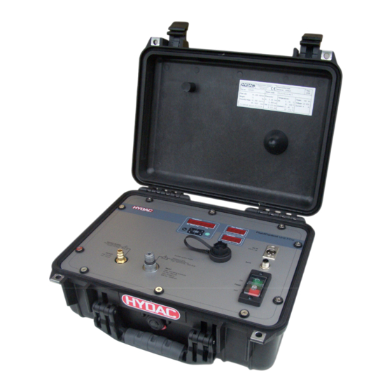
- Page 1 FCU 1000 Series FluidControl Unit Operating and Maintenance Instructions English (translation of original instructions) Valid from firmware versions V 2.00 up Document no.: 3371346d...
-
Page 2: Trademarks
HYDAC FILTER SYSTMES GMBH all rights reserved All rights reserved. This manual may not be reproduced in part or whole without the express written consent of HYDAC FILTER SYSTEMS GMBH. Contraventions are liable to compensation. Exclusion of Liability We made every endeavor to ensure the accuracy of the contents of this document. -
Page 3: Table Of Contents
FCU 1000 Series Contents Contents Trademarks .......................2 Documentation Representative................2 Contents........................3 What's New — Document History................6 Preface ........................7 Technical Support....................8 Modifications to the Product ...................8 Warranty .........................8 Using the Documentation ..................9 Safety Information and Instructions ..............10 Obligations and Liability..................10 Explanation of Symbols and Warnings, etc............11 Proper/Designated Use ..................11... - Page 4 Internal measurement memory ................56 DATA - interface .....................57 Connecting the FCU with CSI-B-2 kit ..............57 Pins used on the DATA interface (HYDAC Sensor Interface – HSI) ....57 Connecting the FCU with HMG 510 / HMG 3000 ..........58 USB interface......................59 Copying measurements onto a USB data stick ............
- Page 5 FCU 1000 Series Contents The measurements are shown as dates ............67 Measurement value readouts with FluMoS............68 Preparing the FCU for transport ................69 Performing maintenance ..................72 Cleaning the FCU ....................72 Rinsing the FCU ....................72 Clean the suction strainer..................75 Checking the high pressure adaptor..............78...
-
Page 6: What's New - Document History
FCU 1000 Series What's New — Document History What's New — Document History The index is featured on the cover sheet of the operating and maintenance manual and in the lower left corner of each page after the part number. -
Page 7: Preface
FCU 1000 Series Preface Preface For you, as the owner of a product manufactured by us, we have produced this manual, comprising the most important instructions for its operation and maintenance. It is intended to help you become acquainted with the ins and outs of the product and use it properly. -
Page 8: Technical Support
Warranty For the warranty provided by us, please refer to the General Terms of Sale and Delivery of HYDAC FILTER SYSTEMS GMBH. Refer to these at www.hydac.com ð General terms and conditions. HYDAC FILTER SYSTEMS GMBH Page 8 / 104 BeWa_FCU1000_3371346d en-us 2010-11-24.doc... -
Page 9: Using The Documentation
FCU 1000 Series Preface Using the Documentation Please note that the method described above of locating specific information does not release you from your responsibility for carefully reading the entire manual prior to starting the unit up for the first time and carefully rereading the manual at regular intervals later on. -
Page 10: Safety Information And Instructions
FCU 1000 Series Safety Information and Instructions Safety Information and Instructions These operating instructions contain the key instructions for properly and safely operating the FCU. Obligations and Liability The basic prerequisite for the safe and proper handling and operation of the FCU is knowledge of the safety instructions and warnings. -
Page 11: Explanation Of Symbols And Warnings, Etc
FCU 1000 Series Safety Information and Instructions Explanation of Symbols and Warnings, etc. The following designations and symbols are used in this manual to designate hazards, etc.: DANGER denotes situations DANGER which can lead to death if safety precautions are not observed. -
Page 12: Improper Use Or Use Deviating From Intended Use
FCU 1000 Series Safety Information and Instructions Improper Use or Use Deviating from Intended Use Improper use may result in hazards like the following: Use of the FCU 1000 for permanent monitoring (i.e. continuous operation) Improper connection of the FCU pressure or return hoses. -
Page 13: Training And Instruction Of Personnel
FCU 1000 Series Safety Information and Instructions Training and Instruction of Personnel The owner is obliged to only let persons work on the FCU, who: are familiar with the fundamental occupational safety and accident prevention regulations and have been properly instructed in the use of the FCU. -
Page 14: Transporting The Fcu
FCU 1000 Series Transporting the FCU Transporting the FCU Transport the FCU only when it is closed position; carry it flat or by the handle. HYDAC FILTER SYSTEMS GMBH Page 14 / 104 BeWa_FCU1000_3371346d en-us 2010-11-24.doc 2010-11-24... -
Page 15: Storing The Fcu
FCU 1000 Series Storing the FCU Storing the FCU Drain and rinse the FCU completely before putting it into storage. See page 72 for details on rinsing the FCU. Observe the following storage conditions: Storage temperature: -40 … +80°C / -40 … +176°F Relative humidity: max. -
Page 16: Decoding The Model Code Label
FCU 1000 Series Decoding the model code label Decoding the model code label For identification of the FluidControl Unit, see the type label. The label shows product ID and major technical application data. See page 98.for more details on the model code. -
Page 17: Checking The Scope Of Delivery
The following items are supplied: Item Description FluidControl Unit FCU 1000 Series, including attachable bag for cables and hoses Power supply, primary: 90-240 V AC / secondary: 24 V DC, 5 Connection cable (Europe, USA/Canada, UK, Australia, Japan) INLET suction hose, open end, clear-transparent, L = 0.3 m... -
Page 18: What The Fcu 1000 Can Do
FCU 1000 Series What the FCU 1000 can do What the FCU 1000 can do The FCU 1000 is a portable service unit for hydraulic systems for intermittent measurement of the particulate contamination, the moisture content in % saturation and the temperature of the fluid. -
Page 19: Restrictions On The Use Of The Fcu 1000
FCU 1000 Series What the FCU 1000 can do Restrictions on the use of the FCU 1000 NOTICE Impermissible operating conditions The FCU will be destroyed ► Use the FCU with mineral oils or mineral oil-based raffinates whose flash point is higher than 55°C/131°F. -
Page 20: Counting Particles In The Fcu 1000
FCU 1000 Series Counting particles in the FCU 1000 Counting particles in the FCU 1000 The measuring principle of the light blocade procedure is shown in simplified form in the following sketch. The light source transmits monochromatic light through the flow of oil to a photo detector, which produces a particular electrical signal. -
Page 21: How The Fcu 1000 Functions
FCU 1000 Series How the FCU 1000 functions How the FCU 1000 functions INLET OUTLET From the oil source (either a pressure port or a bottle sample), a continuous oil current is established through the INLET (1) connector by an electrically controlled gear pump (3). -
Page 22: User Interface Of The Fcu 1000
FCU 1000 Series How the FCU 1000 functions User interface of the FCU 1000 Item Description Display of “ISO, SAE/NAS, Flow, Drive” with keypad Display of the percentage "water saturation" "Fluid temperature" display ON / OFF switch for the internal pump... -
Page 23: Dimensions Of The Fcu 1000
FCU 1000 Series How the FCU 1000 functions Dimensions of the FCU 1000 FCU open: ≈ 450 FCU closed: ≈ 330 HYDAC FILTER SYSTEMS GMBH Page 23 / 104 BeWa_FCU1000_3371346d en-us 2010-11-24.doc 2010-11-24... -
Page 24: Hydraulic Diagram
FCU 1000 Series How the FCU 1000 functions Hydraulic diagram INLET OUTLET Item Description INLET, test connector type 1604 Suction screen, 400 µm Gear pump Electric motor Pressure control valve ContaminationSensor Unit Counter balance valve AquaSensor AS 1000 OUTLET, DN7 Quick coupling nipple... -
Page 25: Using The Batterypack (Accessory)
FCU 1000 Series Using the BatteryPack (accessory) Using the BatteryPack (accessory) With the BatteryPack, which is available as an accessory, you can make the FCU independent of the electrical supply network. For technical details on the BatteryPack, see its instruction brochure. - Page 26 FCU 1000 Series Using the BatteryPack (accessory) To fit the BatteryPack into its holder, proceed as follows: 1. Remove the connector (A) from the socket on the BatteryPack. 2. Slide the BatteryPack into the mounting rails from above. 3. Pull the locking pin (1)
- Page 27 FCU 1000 Series Using the BatteryPack (accessory) To remove it, proceed as follows: 1. Remove the connector from the socket. 2. Pull the locking pin out to release the BatteryPack (1). Slide the BatteryPack upwards (2). 3. Pull the BatteryPack up and out of the mounting rails.
-
Page 28: Preparing The Fcu For Measurement
(included in the FCU delivery) into this. Plug the power supply into the main electricity supply. After the unit is plugged in, HYDAC FCU 1### appears in moving letters, followed by the firmware version, which appears for 2 seconds. -
Page 29: Connecting/Disconnecting The Outlet Hose
FCU 1000 Series Preparing the FCU for measurement Connecting/disconnecting the OUTLET hose NOTICE If the OUTLET connection is closed or blocked The FCU will be damaged. ► Never seal the OUTLET connection. ► Put the free end of the OUTLET return hose into an unpressurized container. -
Page 30: Selecting The Measurement Point
FCU 1000 Series Preparing the FCU for measurement Selecting the measurement point Select the measurement location so that the sample measured comes from a turbulent location, with a good flow. For example on a pipe bend. This ensures that a typical sample is analyzed. -
Page 31: Select The Measurement Method According To The Pressure Involved
FCU 1000 Series Preparing the FCU for measurement Select the measurement method according to the pressure involved After you have selected the measurement location according to the above- mentioned criteria, determine what the operating pressure is at that location. Select the measurement method that is suitable for the pressure at the measurement point. -
Page 32: Measuring Up To Max. 45 Bar / 650 Psi
FCU 1000 Series Measuring up to max. 45 bar / 650 psi Measuring up to max. 45 bar / 650 psi WARNING Hydraulic systems are under pressure Danger of bodily injury ► The system must be depressurized before starting work on it. - Page 33 FCU 1000 Series Measuring up to max. 45 bar / 650 psi 1 ... 45 bar max. 14 ... 650 psi max. 0.5 bar max. 7.5 psi max. Make sure to follow the sequence specified here:Make sure to follow the sequence specified here: 1.
- Page 34 FCU 1000 Series Measuring up to max. 45 bar / 650 psi 3. Connect the INLET pressure hose (black) to the INLET port (1) of the FCU. Screw the measurement coupling clockwise (2) onto the connection and screw it finger tight.
-
Page 35: Measuring In The Range 5 To 345 Bar / 217 To 5000 Psi
FCU 1000 Series Measuring in the range 5 to 345 bar / 217 to 5000 psi Measuring in the range 5 to 345 bar / 217 to 5000 psi WARNING Hydraulic systems are under pressure Danger of bodily injury ► The system must be depressurized before starting work on it. - Page 36 FCU 1000 Series Measuring in the range 5 to 345 bar / 217 to 5000 psi 15 ... 345 bar max. 217 ... 5000 psi max. 0.5 bar max. 7.5 psi max. Make sure to follow the sequence specified here:Make sure to follow the sequence specified here: 1.
- Page 37 FCU 1000 Series Measuring in the range 5 to 345 bar / 217 to 5000 psi 3. Screw the high pressure adaptor onto the FCU's INLET connection. 4. Connect the high pressure hose to the high pressure adaptor. 5. Switch on the internal pump, using the switch.
-
Page 38: Measuring From Unpressurized Containers
FCU 1000 Series Measuring from unpressurized containers Measuring from unpressurized containers Required hoses OUTLET return hose Suction hose max. 0.5 bar max. 7.5 psi To guarantee valid and direct measurements, the FCU must be primed. To do this, you need approximately 120 ml of oil to completely fill the hydraulic circuit inside the FCU and INLET hose. - Page 39 FCU 1000 Series Measuring from unpressurized containers Make sure that the following sequence is observed: 1. Go through the steps in chapter "FCU für die Messung vorbereiten“ on pages 28 to 31. 2. Connect the suction hose (transparent) to the FCU INLET.
-
Page 40: Operating The Fcu
FCU 1000 Series Operating the FCU Operating the FCU If the FCU is powered up, then it can be used and parameters can be set. In the following, the individual controls and their use are described. Display and keypad elements... - Page 41 FCU 1000 Series Operating the FCU The keyboard consists of six buttons. These buttons are used to operate the FCU and to navigate through the menus (hierarchically structured). Keyboard Description one level down o.k. confirm changed value (lowest level) confirm when changes are to be saved or canceled (top...
-
Page 42: Clicking Through The Display
FCU 1000 Series Clicking through the display Clicking through the display CALIB According to the calibration type ( ) in the power up menu, the following displays can be clicked through with the buttons. ISO.SAE display Display Description 2=1(15 3-digit ISO code... -
Page 43: Iso.sae Display
FCU 1000 Series Clicking through the display ISO.SAE display Display Description 2$2"20 3-digit ISO code SAE/NAS Flow Drive 2-5 µm channel NAS SAE/NAS Drive Flow 5-15 µm channel NAS SAE/NAS Flow Drive 15-25 µm channel NAS SAE/NAS Flow Drive > 25 µm channel NAS... -
Page 44: Measured Variables
FCU 1000 Series Measured variables Measured variables The measurements provide you with information about the purity of the oil in the system concerned. The measurement variables are calibrated. They indicate a measured value with an accuracy of +/- 1/2 ISO codes. -
Page 45: Measured Variable "Temperature
FCU 1000 Series Measured variables Measured variable "Temperature" Display Description The integrated AquaSensor continuously measures the fluid temperature. The output as Celsius °C or Fahrenheit °F can be selected under TP.UNIT on page 55. Example: Temperature = 37.8°C Service variables These values give you information about the determined flow and the light source power within the FCU. -
Page 46: Fcu Configuration Menus
FCU 1000 Series FCU configuration menus FCU configuration menus The sensor has two operating levels with corresponding menus. Menus Description Details are on page Power Up Menu The basic settings for the FCU Settings for the recording and storing of the... -
Page 47: Dat.tim - Date / Time
FCU 1000 Series FCU configuration menus DAT.TIM – date / time In this option you can set or alter the system date / time. If the date has never been set, or if the battery is flat , the system date will be 2000- 01-01 and the time will be 00:00. -
Page 48: Del.mem - Delete Memory
FCU 1000 Series FCU configuration menus DEL.MEM – Delete Memory Here, you permanently delete all of the measurement records in the internal memory. Before deletion, back up all of the measurement records on the USB memory stick. Push the following buttons to:... -
Page 49: Calib - Select Calibration Type
FCU 1000 Series FCU configuration menus CALIB – Select calibration type Under CALIB, select the desired calibration type, either ISO.SAE or ISO.NAS. The calibration type ISO.SAE is based on ISO4406:1999 / SAE. The calibration type ISO.NAS is based on ISO4406:1987 / NAS. -
Page 50: Cancel
FCU 1000 Series FCU configuration menus CANCEL CANCEL discards all changes and exits the popup menu. Use the following buttons: Contamination CANCEL Change to the next option in the menu SAE/NAS Confirm o.k. Cancel and back SAVE – store data SAVE stores all of your changes and exits the popup menu. -
Page 51: Measuring Menu
FCU 1000 Series FCU configuration menus Measuring Menu The measuring menu allows you to change settings during operation. Selection To do Start the measuring menu o.k. Press the button o.k. CANCEL Scroll to and press or wait Exit the measuring menu without... -
Page 52: Record - Recording Measurements
FCU 1000 Series FCU configuration menus RECORD - recording measurements With this option you define under which of the 20 available measurement points the records should be saved. Use the following buttons: Contamination RECORD Change to the next option in the menu... -
Page 53: Memory - Display Free Memory
FCU 1000 Series FCU configuration menus MEMORY – display free memory Under MEMORY, you check the current free internal memory capacity of the FCU in %. If there is no more memory available, no measurement records can be saved. Copy the measurement records that you have already read out as described on page 59Fehler! Textmarke nicht definiert.. -
Page 54: Ed.mpnt - Change The Name Of Measurement Points
FCU 1000 Series FCU configuration menus ED.MPNT – Change the name of measurement points Under ED.MPNT you can modify the names of the measurement points to meet your requirements. You only have 6 characters available for the name. For example TEST01, DIGGER, CRANE etc. -
Page 55: Tp.unit - Change The Temperature Units °C / °F
FCU 1000 Series FCU configuration menus TP.UNIT – change the temperature units °C / °F Under TP.UNIT you set the units to display the fluid temperature. You have the choice between Celsius °C and Fahrenheit °F. Use the following buttons:... -
Page 56: Performing A Measurement
FCU 1000 Series Performing a measurement Performing a measurement Check all the hydraulic and electrical connections to the FCU. Now press the green "Pump ON" switch. The pump feeds oil to be analyzed through the FCU. After the set measurement duration, the result will be shown on the display, and the status LED will light up green, steadily. -
Page 57: Data - Interface
FCU 1000 ZBE 08S-02 ZBE 08S-05 DATA Bluetooth max. 10 m Pins used on the DATA interface (HYDAC Sensor Interface – HSI) The HSI interface has connection plug M12x1, 5-pole, in accordance with DIN VDE 0627. Assignment Not connected Not connected... -
Page 58: Connecting The Fcu With Hmg 510 / Hmg 3000
FCU 1000 Series DATA - interface Connecting the FCU with HMG 510 / HMG 3000 The following portable data recorders (HMGs) can be used to give a readout of the FCU 1000 via the DATA interface. HMG 510 (with firmware version 2, release 15 or higher) ... -
Page 59: Usb Interface
This means that communication errors can't be corrected in software, as on a PC with an operating system. We recommend using the HYDAC USB memory stick, which we successfully tested for many PC/operating system combinations. - Page 60 FCU 1000 Series USB interface 3. After inserting the USB memory stick, Contamination DWNLOD LOGS the FCU will detect it and immediately start copying the measurement data. SAE/NAS 4. In the "Contamination" display, you can Contamination see the number of measurement records to be copied (e.g.
-
Page 61: Data Transmission Failed - "Error Copy
->a. If the error recurs -> go to step 10. ->b. If the error does not recur -> go to step 11. Contact the HYDAC service department. The download has been successfully completed HYDAC FILTER SYSTEMS GMBH Page 61 / 104 BeWa_FCU1000_3371346d en-us 2010-11-24.doc... -
Page 62: Bluetooth Interface
FCU 1000 Series Bluetooth interface Bluetooth interface The FCU 1000 Bluetooth interface is based on Bluetooth Version 1.2, Class 3. This means that: Bluetooth Version 1.2: is less sensitive to static disturbances (e.g. WLAN), the maximum data transfer rate is 732.2 kBit/s ... -
Page 63: Installing The Bluetooth Usb Adaptor
PC/operating system combinations. We cannot guarantee the functionality and (looks something like this) compatibility of the Bluetooth USB adaptor For HYDAC part-no., see page with your system. We do not offer support or 86, chapter "Zubehör". replacements in this case. -
Page 64: Evaluating Stored Records
FCU 1000 Series Evaluating stored records Evaluating stored records The measurement records read out of the FCU and stored on the USB memory stick are defined as follows. Directories to store the records by measurement points If measurements are to be stored under a measurement point MNPT, the FCU will automatically produce a directory for this measurement point and will put the record there. -
Page 65: Evaluating The File Containing The Measurements
FCU 1000 Series Evaluating stored records Evaluating the file containing the measurements The file containing the measurements has a file extension, for example "026". This extension may not be recognized by your PC. This means that you must tell your PC that, in future, you would like to open this file with MS Excel. - Page 66 FCU 1000 Series Evaluating stored records The "State" status can take the following values: Fault Description Code Ready => Sensor / equipment is working Minor fault / warning => Sensor / equipment continues to work A warning that is automatically reset by the FCU.
-
Page 67: The Measurements Are Shown As Dates
FCU 1000 Series Evaluating stored records The measurements are shown as dates On opening the file, all decimal numbers will be shown as dates. To resolve this, proceed as follows: 1. Start Excel. 2. From the menu bar, select the "Open"... -
Page 68: Measurement Value Readouts With Flumos
FCU 1000 Series Measurement value readouts with FluMoS 7. Click on the "Finish" button, to Text conversion assistant - step 3 of 3 Data format of the columns complete the import of the Standard measurement data. Text Date Do not import column... -
Page 69: Preparing The Fcu For Transport
FCU 1000 Series Preparing the FCU for transport Preparing the FCU for transport CAUTION Hot fluid at the OUTLET Danger of burns ► Before removing the OUTLET hose from the FCU, allow it to cool off. To prepare the FCU for transport, observe the following sequence: Use the switch to turn the internal pump off. - Page 70 FCU 1000 Series Preparing the FCU for transport Remove the hose by turning the connector to the FCU INLET connection anticlockwise. HYDAC FILTER SYSTEMS GMBH Page 70 / 104 BeWa_FCU1000_3371346d en-us 2010-11-24.doc 2010-11-24...
- Page 71 FCU 1000 Series Preparing the FCU for transport Undo the quick-action coupling on the OUTLET hose by lifting the outer ring. Empty the hose into an unpressurized container. To let air into the hose, open it by using a thin object to press in the check valve on the quick-action coupling.
-
Page 72: Performing Maintenance
FCU 1000 Series Performing maintenance Performing maintenance At the latest, conduct the required configuration maintenance and inspection work every six months, otherwise, whenever an error message or malfunction makes it necessary. All operating media are to be protected/isolated in case the product is accidentally started up. - Page 73 FCU 1000 Series Performing maintenance Flush the FCU as described below: Put approx. 0.5 liters of filtered oil into a clean container. Connect the OUTLET return hose to the FCU and put the free end into a container for the used fluid.
- Page 74 FCU 1000 Series Performing maintenance Use the switch on the FCU to turn its pump on. Cleanliness values will be Contamination 2=1(15 displayed during the flushing procedure. SAE/NAS These measurements are not correct, but should decrease during the flushing procedure.
-
Page 75: Clean The Suction Strainer
FCU 1000 Series Performing maintenance Clean the suction strainer. NOTICE Operation without a suction sieve The FCU pump can be damaged ► Never use the FCU without a suction screen. ► Clean the suction screen regularly. The sieve is fitted under the INLET connector and protects the pump from contamination by coarse particles. - Page 76 FCU 1000 Series Performing maintenance 4. Put a finger in the opening ... 5. .. and pull out the suction screen upwards. 6. Clean the sieve by blowing it out with compressed air. Before reassembly, check that the sealing ring for the connector is undamaged.
- Page 77 FCU 1000 Series Performing maintenance 7. Put the sieve back into the opening. 8. Manually screw the INLET connector in clockwise. 9. Using a 19 mm wrench, tighten the INLET connector, turning it clockwise. Note the maximum torque of 25 Nm.
-
Page 78: Checking The High Pressure Adaptor
FCU 1000 Series Performing maintenance Checking the high pressure adaptor In the high pressure adapter there is a 400 µm sieve to protect the flow control valve. Clean this sieve at least every 6 months, or more frequently if heavy soiling makes it necessary. -
Page 79: Cleaning / Changing The Sieve In The High Pressure Adapter
FCU 1000 Series Performing maintenance Cleaning / changing the sieve in the high pressure adapter CAUTION Operation without a sieve The FCU pump can be damaged ► Never use the high-pressure adapter without a sieve. ► Clean the sieve regularly... -
Page 80: Cleaning / Changing The Strainer In The High Pressure Adapter
FCU 1000 Series Performing maintenance Cleaning / changing the strainer in the high pressure adapter CAUTION Wrong installation of the flow control valve Flow control valve is not working ► Pay attention to the direction of flow when installing the flow control valve. -
Page 81: Fcu Status Messages / Error Messages
FCU 1000 Series FCU status messages / error messages FCU status messages / error messages The following error codes are possible. You will find these error codes in the measurement file. Fault Description Code Ready for operation => Sensor / equipment is working Minor fault / warning =>... - Page 82 FCU 1000 Series FCU status messages / error messages LED Display Status To do Fault flashing code Code 2%2$23 The FCU is above its Filter the oil to range of improve its SAE/NAS Flow Drive measurement cleanliness. „DIRTY > ISO 25/24/23.
- Page 83 FCU 1000 Series FCU status messages / error messages LED Display Status To do Fault flashing code Code The AquaSensor is Switch the FCU off EROR causing a moderate and then on again. fault. If the fault recurs, contact HYDAC service department.
-
Page 84: Restart / Resetting The Fcu
FCU 1000 Series Restart / Resetting the FCU Restart / Resetting the FCU To reset the FCU, remove the power supply to the FCU for 10 seconds. To remove the connector To insert the connector 24V DC Press the catch on the connector (1) Insert the connector into the socket until and then pull the connector out (2). -
Page 85: Spare Parts List
FCU 1000 Series Spare Parts List Spare Parts List Part no. Description Figure INLET high pressure hose with screwed joint, for 349150 measurement point type 1620, color: black, L = 2 m (78.74 inch) INLET suction hose with open end, color: clear- 3297276 transparent, Length = 1.5 m (59.06 inch) -
Page 86: Accessories For The Fcu
FCU 1000 Series Spare Parts List Part no. Description Figure Power adaptor (without power cord) 6059933 primary: 100- 240 V AC secondary: 24 V DC, 5A, cable with 3-pole plug, Length = 1.6 m (62.99 inch) 6008448 Connection cable for power adaptor European plug, Length = 2 m (78.74 inch) - Page 87 FCU 1000 Series Spare Parts List Part no. Description Figure 12V/24V DC cable with universal 3524138 plug, including 8A fuse, Length = 1 m (39.37 inches) Fuse 8 A for universal plug 6052824 (Ø 6 x 25 mm, according to DIN...
- Page 88 FCU 1000 Series Spare Parts List Part no. Description Figure Connection cable with 5-pole 6040852 connector <–> 5-pole socket, length 5 m (ZBE 30-05) *) available on request HYDAC FILTER SYSTEMS GMBH Page 88 / 104 BeWa_FCU1000_3371346d en-us 2010-11-24.doc 2010-11-24...
-
Page 89: Overview - Iso 4406 / Sae As 4059 And Nas 1638 Classes
FCU 1000 Series Overview - ISO 4406 / SAE AS 4059 and NAS 1638 classes Overview - ISO 4406 / SAE AS 4059 and NAS 1638 classes ISO 4406:1999 In ISO 4406:1999, particle counts are determined cumulatively, i.e. > 4 µm , >6... -
Page 90: Overview Of The Differences Between Iso 4406:1987 And Iso 4406:1999
FCU 1000 Series Overview - ISO 4406 / SAE AS 4059 and NAS 1638 classes Note: increasing the measurement reference by 1 causes the particle count to double. Example: ISO class 18 / 15 / 11 means: Cleanliness class Particle count / 100 ml Size ranges 130,000 –... -
Page 91: Sae As 4059
FCU 1000 Series Overview - ISO 4406 / SAE AS 4059 and NAS 1638 classes SAE AS 4059 Like ISO 4406, SAE AS 4059 describes particle concentrations in liquids. The analysis methods can be applied in the same manner as ISO 4406:1999. -
Page 92: Specifying A Cleanliness Class For Each Particle Size
FCU 1000 Series Overview - ISO 4406 / SAE AS 4059 and NAS 1638 classes Specifying a cleanliness class for each particle size Example: cleanliness class to AS 4059: 7 A / 7 B / 6 C / 5 D... -
Page 93: Checking The Measuring Accuracy Of The Fcu
FCU 1000 Series Checking the measuring accuracy of the FCU Checking the measuring accuracy of the FCU With the help of the FieldVerification Kit, you can check the error of measurement of the FluidControl Unit FCU 1000 on site based on a fluid defined as contaminated. -
Page 94: Customer Service
Customer service Customer service Current contacts for product support/customer service, repair and spare parts can always be found on our website at www.hydac.com. For calibration, contact one of the following HYDAC national subsidiaries: Germany HYDAC Service GmbH Product Support, Werk 10 66128 Saarbrücken, Germany... -
Page 95: Brazil
FCU 1000 Series Factory default settings Brazil HYDAC TECNOLOGIA LTDA Estrada Fukutaro Yida, 225 CEP 09852-060 Cooperativa BR-São Bernardo do Campo – SÃO PAULO Telephone: +55 - 11 - 4393.6600 Fax: +55 - 11 - 4393.6617 E-mail: hydac@hydac.com.br Homepage www.hydac.com.br Factory default settings If the "DFAULT"... -
Page 96: Technical Data
FCU 1000 Series Technical Data Technical Data Contamination Sensor Self-diagnosis continuously with error indication via status LED and display Display LED, 6 / 4 / 4 digits, in 17 segment format Measured values for solid ISO code / SAE class / NAS class... - Page 97 FCU 1000 Series Technical Data Contamination Sensor color: black, Length = 2 m (78.74 inch) OUTLET return hose DN7, open-end, color: clear-transparent, Length = 1 m Electrical data Supply voltage 24 V DC, ± 20%, residual ripple ≤ 10% Power consumption / electricity 100 W max. / 4 A max.
-
Page 98: Model Code
FCU 1000 Series Model Code Model Code 0 - 4 - U - AS - 1 Product FCU = FluidControl Unit Series = 1000 series, 4 particle size channels Contamination code = ISO4406:1987; NAS 1638 ISO4406:1999; SAE AS4059 (D) Body... -
Page 99: Compatible Usb Sticks - Overview
FCU 1000 Series Compatible USB sticks - overview Compatible USB sticks - overview In the following, you will find an overview of the USB memory sticks which we have tested with the FCU 1000 for compatibility, writing speed and stability in operation. -
Page 100: Ec Declaration Of Conformity
Documentation Representative: Mathias Dieter, Dipl.Kfm. Wolfgang Haerin g Mr. Günter Harge Registered seat of company: 66280 Sulzbach / Saar - Germany c/o HYDAC International GmbH, Industriegebiet, 66280 Sulzbach / Saar Registry Court: Saarbrücken, HRB 17216 Telephone: ++49 (0) 6897 509 1511... - Page 104 HYDAC FILTER SYSTEMS GMBH Industriegebiet Postfach 1251 66280 Sulzbach/Saar 66273 Sulzbach/Saar Germany Germany Phone: +49 (0) 6897 509 01 Central Fax: +49 (0) 6897 509 846 Technical Department Fax: +49 (0) 6897 509 577 (Sales Department) Internet: www.hydac.com E-Mail: filtersystems@hydac.com...
Need help?
Do you have a question about the FCU 1000 Series and is the answer not in the manual?
Questions and answers