Table of Contents
Advertisement
Quick Links
Black Box Tech Support: FREE! Live. 24/7.
Tech support the
way it should be.
About Black Box
Black Box Network Services is your source for more than 118,000 networking
and infrastructure products. You'll find everything from cabinets and racks and
power and surge protection products to media converters and Ethernet switches all
supported by free, live 24/7 Tech support available in 20 seconds or less.
Copyright 2009. All rights reserved.
©
Great tech support is just 20 seconds away
at 724-746-5500 or blackbox.com.
724-746-5500 | blackbox.com
Advertisement
Table of Contents

Related Manuals for Black Box AC1124A


Summary of Contents for Black Box AC1124A
- Page 1 724-746-5500 or blackbox.com. About Black Box Black Box Network Services is your source for more than 118,000 networking and infrastructure products. You’ll find everything from cabinets and racks and power and surge protection products to media converters and Ethernet switches all supported by free, live 24/7 Tech support available in 20 seconds or less.
- Page 2 BLACK BOX ® Simplifies signal routing. The AC1124A model routes a video and audio signal from 2 DVI sources (computers, media players, TV tuners, etc.) to 4 DVI displays (projectors, monitors, and so on) and speakers. The AC1125A model routes a video and audio signal from 4 DVI sources to 2 DVI displays and speakers.
- Page 3 FCC and NOM Statements FEDERAL COMMUNICATIONS COMMISSION AND INDUSTRY CANADA RADIO FREQUENCY INTERFERENCE STATEMENTS This equipment generates, uses, and can radiate radio-frequency energy, and if not installed and used properly, that is, in strict accordance with the manufacturer’s instructions, may cause inter ference to radio communication. It has been tested and found to comply with the limits for a Class A computing device in accordance with the specifications in Subpart B of Part 15 of FCC rules, which are designed to provide reasonable protection against such interference when the equipment...
- Page 4 DVI Matrix Switches 4. Todas las instrucciones de operación y uso deben ser seguidas. 5. El aparato eléctrico no deberá ser usado cerca del agua—por ejemplo, cerca de la tina de baño, lavabo, sótano mojado o cerca de una alberca, etc. 6.
- Page 5 NOM Statement 16. El cable de corriente deberá ser desconectado del cuando el equipo no sea usado por un largo periodo de tiempo. 17. Cuidado debe ser tomado de tal manera que objectos liquidos no sean derramados sobre la cubierta u orificios de ventilación. 18.
- Page 6 DVI Matrix Switches TRADEMARKS USED IN THIS MANUAL Black Box and the Double Diamond logo are registered trademarks of BB Technologies, Inc. Any other trademarks mentioned in this manual are acknowledged to be the property of the trademark owners. 724-746-5500 | blackbox.com...
-
Page 7: Table Of Contents
7.2 Unit Stack ....................39 7.2.1 Set the Remote Control ID on the System ........39 7.2.2 Optimize the Video Signal Strength (for AC1124A Only) .....39 7.2.3 Copy the EDID to the Video Matrix Switch........40 8. Rackmount Kit (Optional) and Multi-Mode Sensor Kits ........41 724-746-5500 | blackbox.com... -
Page 8: Chapter 1. Specifications
Operating Temperature: 41 to 104–176° F (5 to 40–176° C) Resolution Supported (Maximum): 1600 x 1200 at 60 Hz CE Approval: Yes Connectors: AC1124A: Input: (2) DVI-I, (2) 3.5-mm stereo; Output: (4) DVI-I, (4) 3.5-mm stereo; AC1125A: Input (4) DVI-I, (4) 3.5-mm stereo;... -
Page 9: Overview
2. Overview 2.1 Introduction The 2 x 4 Video Matrix Switch with Audio (AC1124A) routes the video signal and audio signal from 2 DVI sources (computers, media players, TV tuners, etc.) to 4 DVI displays (projectors, monitors, and so on) and 4 speakers. The 4 x 2 Video Matrix Switch with Audio (AC1125A) routes the video signal and audio signal from 4 DVI sources to 2 DVI displays (projectors, monitors, and so on) and 2 speakers. -
Page 10: Features
DVI Matrix Switches • Serial Control Cable (2.5-mm plug to DB9 female) (for AC1125A only) • Remote controller • IR Extension Kit (includes [1] mounting plate [magnetic or screw-mount], [1] pivoting sensor holder, [1] 6-foot remote placement cable, and [2] screws) •... -
Page 11: Front Panel
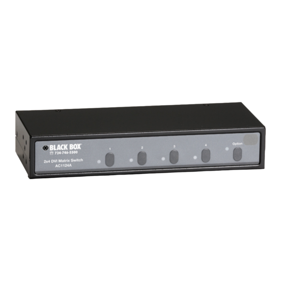
2.4 Front Panel Figures 2-1 and 2-2 show the front panel of the 2 x 4 DVI Matrix Switch (AC1124A) and the 4 x 2 DVI Matrix Switch (AC1125A). Table 2-1 describes both switches’ components. Figure 2-1. AC1124A front panel. -
Page 12: Rear Panel
DVI Matrix Switches 2.5 Rear Panel Figures 2-3 and 2-4 show the switch’s rear panels. Tables 2-2 and 2-3 describe the components. Figure 2-3. AC1124A rear panel. Table 2-2. AC1124A rear panel components. Number Component Description Source 1 and Source 2 connectors... - Page 13 Chapter 2: Overview Figure 2-4. AC1125A rear panel. Table 2-3. AC1125A rear panel components. Number Component Description Monitors 1 and 2 connectors (2) DVI-I Monitors 1 and 2 audio connectors (2) 3.5-mm stereo Source 1, 2, 3, and 4 connectors (4) DVI-I Source 1, 2, 3, and 4 audio connectors (4) 3.5-mm stereo...
-
Page 14: Installation (Ac1124A)
DVI Matrix Switches 3. Installation (AC1124A) Follow these steps to install the 2 x 4 DVI Matrix Switch (AC1124A). 3.1 Input Connection 1. Connect the source’s DVI video port to the switch’s source 1 video port. See Figure 3-1. AC1124A... - Page 15 Chapter 3: Installation (AC1124A) 2. Connect the source’s speaker port to the switch’s source 1 audio port. See Figure 3-2. AC1124A Source 1 audio port Computer speaker port Source DVI video port Figure 3-2. Linking the source’s speaker port to the switch’s source 1 audio port.
-
Page 16: Output Connection
DVI Matrix Switches 3.2 Output Connection 1. Connect your monitor 1 to the switch’s video port 1. See Figure 3-4. Source 1 Source 2 monitor 1 Figure 3-4. Attaching monitor 1 to switch’s video port 1. 2. Connect a pair of speakers to the switch’s audio port 1. See Figure 3-5. NOTE: Speakers may be integrated with the monitor or separate. - Page 17 Chapter 3: Installation (AC1124A) 3. Repeat Steps 1 and 2 for the switch’s video port 2 and audio port 2. See Figure 3-6. Speakers Source 2 DVI monitors 1 through 4 Source 1 Figure 3-6. Linking video port 2 and audio port 2.
- Page 18 DVI Matrix Switches 4. Power on the switch. See Figure 3-7. Speakers DVI monitors 1 through 4 Source 2 Power connection Source 1 Figure 3-7. Powering on the switch. 724-746-5500 | blackbox.com Page 16...
-
Page 19: Installation (Ac1125A)
Chapter 4: Installation (AC1125A) 4. Installation (AC1125A) Follow these steps to install the 4 x 2 DVI Matrix Switch (AC1125A). 4.1 Input Connection 1. Connect the source’s DVI video port to the switch’s source 1 video port. See Figure 4-1. AC1125A Source Links to DVI... - Page 20 DVI Matrix Switches 2. Connect the source’s speaker port to the switch’s source 1 audio port. See Figure 4-2. Source 1 AC1125A audio port Source Computer speaker port DVI video port Figure 4-2. Linking the source’s speaker port to the switch’s source 1 audio port. 724-746-5500 | blackbox.com Page 18...
- Page 21 Chapter 4: Installation (AC1125A) 3. Repeat Steps 1 and 2 for source 2. See Figure 4-3. Source 2 Source 1 audio port audio port Computer Computer speaker port speaker port Source Source Figure 4-3. Connections for source 2. 724-746-5500 | blackbox.com Page 19...
-
Page 22: Output Connection
DVI Matrix Switches 4.2 Output Connection 1. Connect your monitor 1 to the switch’s video port 1. See Figure 4-4. 2. Connect a pair of speakers to the switch’s audio port 1. See Figure 4-4. NOTE: Speakers may be integrated with the monitor or separate. 3. -
Page 23: Basic Operation (Ac1124A)
5. Basic Operation (AC1124A) 5.1 Front Panel Once the unit is powered on, all four red LEDs will light. By default, the AC1124A switch routes source 1 to monitors 1 through 4. When all four LEDs are blinking, source 1 is empty or not detected. When all four LEDS are steady on, the switch detects the video signal from source 1. -
Page 24: Remote Control
DVI Matrix Switches 5.2 Remote Control You can control the switch remotely in two ways. When the external sensor is not connected to the switch, the internal sensor works with the remote controller. When the external sensor is connected to the switch, the internal sensor is disabled, and the remote control works with the external sensor. - Page 25 Chapter 5: Basic Operation (AC1124A) 3. Press “S1“ or ”S2” to route source 1 or 2 to monitor 4 (M4). See Figure 5-5. Figure 5-5. S1/S2/S3/S4 buttons on the remote control. 4. Repeat Steps 1 and 3 for routing other ports.
-
Page 26: Basic Operation (Ac1125A)
DVI Matrix Switches 6. Basic Operation (AC1125A) 6.1 Front Panel Once the unit is powered on, all four red LEDs will light. By default, the AC1125A routes source 1 to monitors 1 or 2. When all four LEDs are blinking, source 1 is empty or not detected. -
Page 27: Remote Control
Chapter 6: Basic Operation (AC1125A) 3. Press 1, 2, 3, or 4 within 3 seconds to select source 1 2, 3, or 4. After you select a source, the LED “2” will become either “red” or “orange.” “Red” means Source 1 is selected. “Orange”... - Page 28 DVI Matrix Switches 2. Press the desired port, for example, “2.” See Figure 6-4. Figure 6-4. Monitor 2 button on remote control. 3. Press “S1/S2/S3/S4” to route source 1/2/3/4 to monitor 2 (M2). See Figure 6-5. Figure 6-5. S1/S2/S3/S4 buttons on the remote control. 724-746-5500 | blackbox.com Page 26...
- Page 29 Chapter 6: Basic Operation (AC1125A) 4. Repeat Steps 1 and 3 for routing other ports. To turn the video or audio ON/OFF, simply press the “VIDEO” button or the “AUDIO” button. Figure 6-6. Video and audio buttons on the remote control. 724-746-5500 | blackbox.com Page 27...
-
Page 30: Serial Control
DVI Matrix Switches 6.3 Serial Control The DVI Matrix Switch’s built-in serial interface allows users to control the switch through a PC, serial controller devices, or home theater system. NOTE: Use a 2.5-mm plug to DB9 F connector cable (included). Configure the controller’s serial port as shown below: Baud rate: 9600 Data bits: 8... - Page 31 Chapter 6: Basic Operation (AC1125A) To select a source device via serial interface, select the number that corresponds to the port it is connected to as shown in Figure 6-8. -------------------------------------------------------------------------- 0. Display System Status 1. Configure Monitor 1. 2. Configure Monitor 2. 9.
- Page 32 DVI Matrix Switches Source 4: No Video Signal Detected. Auto Scan Time Interval: 8 seconds. Remote Controlling ID: 1 ------------------------------------------------------------------------ ----------------------------------------- 0. Display System Status. 1. Configure Monitor 1. 2. Configure Monitor 2. 9. Set Auto Scan Time Interval. Choice: 2 Monitor 2 Configuration.
- Page 33 Chapter 6: Basic Operation (AC1125A) Source 1: Video Signal Detected. Source 2: No Video Signal Detected. Source 3: No Video Signal Detected. Source 4: No Video Signal Detected. Auto Scan Time Interval: 8 seconds. Remote Controlling ID: 1 ------------------------------------------------------------------------ ------------------------------------------------------------------------ 0.
- Page 34 DVI Matrix Switches Choice: 1 Monitor 1 Configuration. 0. Display System Status. 1. Route Source 1 to Monitor 1. 2. Route Source 2 to Monitor 1. 3. Route Source 3 to Monitor 1. 4. Route Source 4 to Monitor 1. 7.
- Page 35 Chapter 6: Basic Operation (AC1125A) 1. Route Source 1 to Monitor 1. 2. Route Source 2 to Monitor 1.. 3. Route Source 3 to Monitor 1. 4. Route Source 4 to Monitor 1. 7. Set Video ON/OFF 8. Set Audio ON/OFF 9.
- Page 36 DVI Matrix Switches When a user plugs or unplugs the Matrix Switch’s DVI cable, the administrator can see it on the terminal window immediately. Source Status Changed. Source 1 text. ------------------------------------------ 0. Display System Status. 1. Configure Monitor 1. 2. Configure Monitor 2. 9.
-
Page 37: Advanced Operation (Ac1124A Or Ac1125A)
Chapter 7: Advanced Operation (AC1124A or AC1125A) Advanced Operation (AC1124A or AC1125A) 7.1 Front Panel 7.1.1 Turn the Video ON/OFF 1. Press the desired port button, for example, “2.” Figure 7-1. Port button 2. 2. Press AND hold “Option.” LED 1 lights. -
Page 38: Turn The Audio On/Off
DVI Matrix Switches 7.1.2 Turn the Audio ON/OFF 1. Press the desired port, for example, “2.” Figure 7-4. Button 1: power off audio. 2. Press and hold “Option.” LED 2 lights. LED 2: Green light means the monitor’s audio output is turned on. Red light means it is turned off. -
Page 39: Turn The Autoscan On/Off
Chapter 7: Advanced Operation (AC1124A or AC1125A) 7.1.3 Turn the AutoScan ON/OFF In this auto scan mode, the AC1124A switch automatically switches between source 1 to source 2 sequentially in a fixed interval for a particular monitor. 1. Press the desired port, for example, “4.”... -
Page 40: Set The Auto Scan Time Interval
“1” represents 8 seconds. “2” represents 15 seconds. “3” represents 30 seconds. “4” represents 45 seconds. 7.1.5 Restore Default Settings AC1124A: 1. Power OFF the switch. 2. Press AND hold “Option.” 3. Power ON the switch and press “1.” 4. Release “Option.”... -
Page 41: Unit Stack
The factory default remote control ID is 1. 7.2.2 Optimize the Video Signal Strength (for AC1124A Only) Adjust the optimal video signal strength corresponding to the length or quality of DVI cable since each monitor can be routed to one of the two input sources. As a result, each monitor has two different video strength settings. -
Page 42: Copy The Edid To The Video Matrix Switch
DVI Matrix Switches ν Press “4” one, two, three, or four times to adjust the selected port’s output priority. LED 4 lights “green” for no priority, lights “yellow” for low priority, lights “orange” for medium priority, or lights “red” for high priority. 5. -
Page 43: Rackmount Kit (Optional) And Multi-Mode Sensor Kits
Chapter 7: Advanced Operation (AC1124A or AC1125A) 8. Rackmount Kit (optional) and Multi-Mode Remote Sensor Kits Figure 8-1 shows how to attach optional mounting brackets to the Video Matrix Switch fo the industrial standard 19-inch rack cabinet. The mounting brackets are available by special order only. - Page 44 DVI Matrix Switches Figures 8-3 through 8-5 show the switch in different modes. 1. Wallmount (use screws and the metal plate to fasten the multi-mode stand in its proper position. Figure 8-3. Wallmount sensor. 2. Pedestal (use a metal plate to fasten the multi-mode stand in its proper position. Figure 8-4.
Need help?
Do you have a question about the AC1124A and is the answer not in the manual?
Questions and answers