
Subscribe to Our Youtube Channel
Related Manuals for CAME KM4G081C


Summary of Contents for CAME KM4G081C
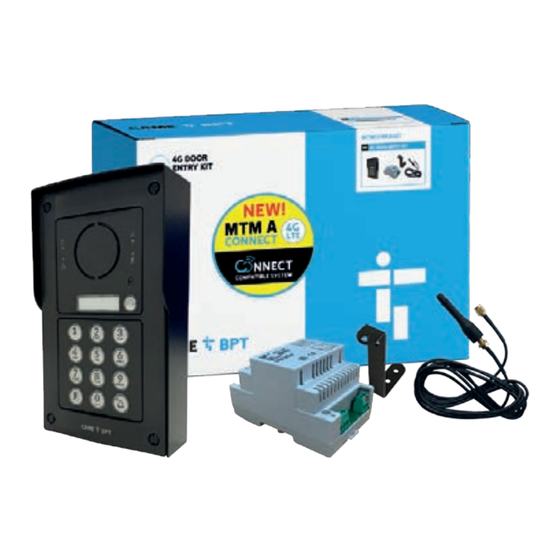
- Page 1 CAME.COM/UK MTMA/connect with keypad Covering MTM / MTMVR / VRW / VRM Surface/Flush Mount 4G Audio Intercom with Keypad quick setup reference guide KM4G081C for full instructions please refer to the installation manual...
-
Page 2: Table Of Contents
MTM Call Panel MTM VR Call Panel VRW Call Panel VRM Call Panel Intercom Intercom Intercom Intercom VAS/101 antenna mounting box rain hood CAME Key Power Supply With cable and For flush mount or surface mount WiFi Interface mounting bracket intercoms... -
Page 3: General Precautions
general precautions • Read the instructions carefully before beginning the installation and carry out the actions as specified by the manufacturer. • The installation, programming, commissioning and maintenance of the product must only be carried out by qualified technicians, properly trained in compliance with the regulations in force, including health and safety measures and the disposal of packaging. -
Page 4: Dimensions
TITLE dimensions Size 1 Size 2 Size 3 Size 4 Type Mounting W x H x D (mm) 135 x 228 x 64 135 x 318 x 64 135 x 408 x 64 Surface 130 x 226 x 62 130 x 316 x 62 130 x 406 x 62 (48mm depth (48mm depth... -
Page 5: Pre-Commissioning
pre-commissioning inserting the micro sim card 1. Please ensure that the module is disconnected from the mains power. 2. Insert the Micro SIM card into the slot as shown in the diagram Please note: the Micro SIM is not included with the kit and will need to be purchased separately. - Page 6 installation: recessed Items illustrated may differ from kit contents. All modules & frames are fitted in the same way. • Fit the aluminium module-housing profile into the recess mounting box • Slide the electronic modules into place • Screw the outer frame into place over the modules, •...
- Page 7 TITLE installation: surface Items illustrated may differ from kit contents. All modules & frames are fitted in the same way. • Fit the aluminium module-housing profile into the rain hood • Slide the electronic modules into place • Screw the outer frame into place over the modules, •...
- Page 8 TITLE installation: recessed Items illustrated may differ from kit contents. All modules & frames are fitted in the same way. • Fit the aluminium module-housing profile into the recess mounting box • Slide the electronic modules into place • Snap the pre-configured front panels securely into place over the modules, using the clips circled •...
- Page 9 TITLE installation: surface Items illustrated may differ from kit contents. All modules & frames are fitted in the same way. • Fit the aluminium module-housing profile into the recess mounting box • Slide the electronic modules into place • Snap the pre-configured front panels securely into place over the modules, using the clips circled •...
- Page 10 TITLE installation: recessed Items illustrated may differ from kit contents. All modules & frames are fitted in the same way. • Fit the aluminium module-housing profile into the recess mounting box • Slide the electronic module(s) into place • Connect the ribbon cable from the button to the •...
- Page 11 TITLE installation: surface Items illustrated may differ from kit contents. All modules & frames are fitted in the same way. • Fit the aluminium module-housing profile into the recess mounting box • Slide the electronic module(s) into place • Connect the ribbon cable from the button to the •...
-
Page 12: Configuration
MTMA/CONNECT – Audio Module Speaker CAME KEY adapter (88040-0055) LED warning light: conversation in progress (yellow) Antenna plug LED warning light: door open (green) Micro SIM card Connector for CAME KEY Slot for Micro-SIM-CARD (Push-Push) Microphone Hearing-impaired module housing... - Page 13 configuration MTMKB - keypad module Sockets for the connector to connect additional modules. Description Power supply (V DC) 10.7 to 18 Keypad module for access-control, connectible on MAX consumption (mA) BUS. Cut off the power supply before fitting or MIN consumption (mA) removing the module.
-
Page 14: Wiring Diagrams
wiring diagram MTMA/CONNECT CONTROL BOARD VAS/101 12v DC Push to Open Strike Cable/length Switch 25m (2x1mm ) or 60m (2x2.5mm... - Page 15 wiring diagram MTMA/CONNECT CONTROL BOARD GATE OPERATOR CONTROL BOARD 12v DC Push to Open Strike A B GND 11 10 Switch...
- Page 16 Should adding the gateway the email not arrive, please to your technician account check your junk folder. 3.1 Select “CAME Connect 3.2 Select “Managing 3.3 You can either select an 3.4 Select “Add Gateway”. connection” in order to Installations”...
-
Page 17: Commissioning Via App
3.5 You can now use the app 3.6 Give the device a name 3.7 You will now see this 3.8 Plug in the CAME KEY (using to scan the QR code on the and a description. When screen as the system has the supplied adaptor) into the done, press “Add”... - Page 18 This new button manages the CAME KEY, as it is no longer Door Entry functions, which we required. will look at next - otherwise it acts like a normal CAMEconnect gateway, and devices can be added to it in the normal manner.
- Page 19 TITLE commissioning via app 4.9 Now let’s add the right 4.10 If no call button 4.7 Or you can select NO 4.8 When happy with the destinations (units) have been hand call button. On the buttons – or press the button configuration, press BACK programmed previously, you image of the base module on...
- Page 20 commissioning via app Main House 4.15 We can now associate 4.16 Now select the desination 4.17 If there are no contacts 4.18 A list of available associated yet with the contacts is shown, you can the Contacts to the Call i.e Main House Buttons.
- Page 21 TITLE commissioning via app coded keypad configuration 1234 1234 5.3 We will be asked to confirm 5.4 Any existing PIN codes for 5.1 To add in an additional 5.2 If we are going to add an MTM module to the unit, we additional module to the MTM the choice, and once done, the access will be shown here.
- Page 22 TITLE commissioning via app 5.9 It will show the current PIN 5.10 Select Access Control 5.11 Once this is done, the 5.12 Either touch the number Access Mode state – which only from the options (as previous screen will have in the white box and type in by default is MTM/KB –...
- Page 23 commissioning via app configuring the crp gateway 6.1 From the Device menu 6.2 A menu will appear (see 6.3 Select the Operator 6.4 Your selected operator within the site, press the three right) with a series of options. type (in the example we will now appear below the dots icon to the right of the As per normal when adding...
- Page 24 COMMISSIONING VIA APP OPTIONAL: If you choose to transfer site ownership to your customer, you will lose the ability to remotely manage this system, unless your customer raises a support transfer to request giving you permission to access the system. customer Transferring site ownsership will allow your customer to make changes to the system.
- Page 25 settings The APN settings listed below are correct as at March 2024, but may be subject to change from the Mobile Network Operator. Should the below settings not work for your sim, please contact the Mobile Network Provider who will be able to confirm the correct APN to use.
- Page 26 DTMF settings The system has preset DTMF tone settings. During a call pressing a key combination will carry out a specific function. For example to increase the volume on the speaker Key 1#. There are 8 of these that are set by default. 4 of which cannot be changed. The other 4 can be modified from their default settings if required.
- Page 27 DTMF settings changing dtmf shortcut keys 10.1 From the Main Menu 10.2 To change the preset 10.3 Select Modify. 10.4 Replace the code with Press “DTMF tones”. DTMF key combination press your desired key combination the 3 dots as pictured above. Note: key combinations must be a minimum of 2 characters.
- Page 28 YOU MAY NOT EVEN PARTIALLY REPRODUCE THIS DOCUMENT CAME RESERVES THE RIGHT TO MAKE ANY CHANGES TO THIS DOCUMENT AT ANY TIME THE DATA AND INFORMATION SHOWN IN THIS CATALOGUE ARE SUBJECT TO CHANGE WITHOUT OBLIGATION TO GIVE PRIOR NOTICE BY CAME S.P.A, E&OE CAME S.p.A.
Need help?
Do you have a question about the KM4G081C and is the answer not in the manual?
Questions and answers